fuel filter location ISUZU KB P190 2007 Workshop Repair Manual
[x] Cancel search | Manufacturer: ISUZU, Model Year: 2007, Model line: KB P190, Model: ISUZU KB P190 2007Pages: 6020, PDF Size: 70.23 MB
Page 1551 of 6020
6C-10 FUEL SYSTEM (4JK1/4JJ1)
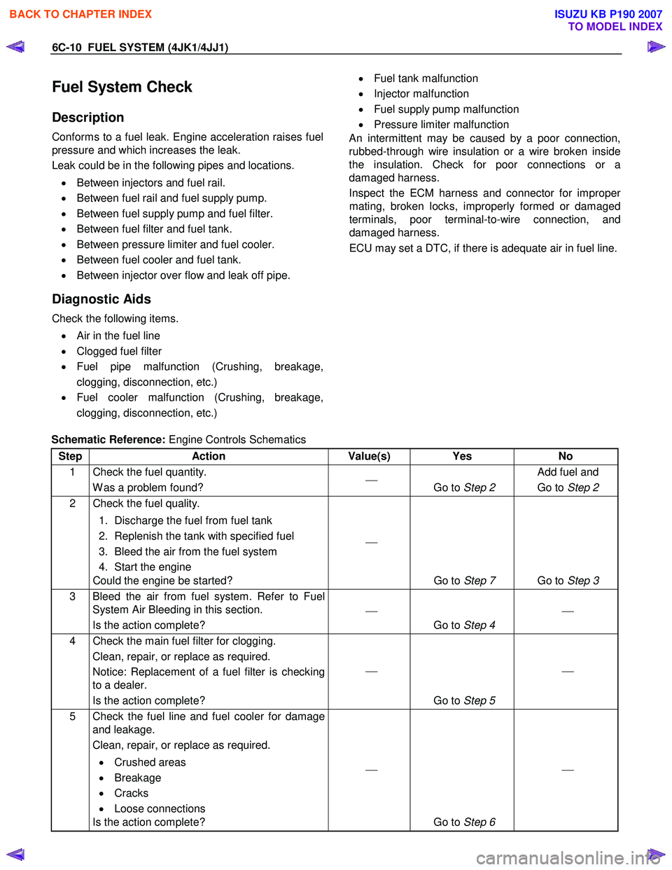
Fuel System Check
Description
Conforms to a fuel leak. Engine acceleration raises fuel
pressure and which increases the leak.
Leak could be in the following pipes and locations.
• Between injectors and fuel rail.
• Between fuel rail and fuel supply pump.
• Between fuel supply pump and fuel filter.
• Between fuel filter and fuel tank.
• Between pressure limiter and fuel cooler.
• Between fuel cooler and fuel tank.
• Between injector over flow and leak off pipe.
Diagnostic Aids
Check the following items.
• Air in the fuel line
• Clogged fuel filter
• Fuel pipe malfunction (Crushing, breakage,
clogging, disconnection, etc.)
• Fuel cooler malfunction (Crushing, breakage,
clogging, disconnection, etc.)
• Fuel tank malfunction
• Injector malfunction
• Fuel supply pump malfunction
• Pressure limiter malfunction
An intermittent may be caused by a poor connection,
rubbed-through wire insulation or a wire broken inside
the insulation. Check for poor connections or a
damaged harness.
Inspect the ECM harness and connector for imprope
r
mating, broken locks, improperly formed or damaged
terminals, poor terminal-to-wire connection, and
damaged harness.
ECU may set a DTC, if there is adequate air in fuel line.
Schematic Reference: Engine Controls Schematics
Step Action Value(s) Yes No
1 Check the fuel quantity. W as a problem found?
Go to Step 2 Add fuel and
Go to Step 2
2 Check the fuel quality.
1. Discharge the fuel from fuel tank
2. Replenish the tank with specified fuel
3. Bleed the air from the fuel system
4. Start the engine
Could the engine be started?
Go to Step 7 Go to Step 3
3 Bleed the air from fuel system. Refer to Fuel
System Air Bleeding in this section.
Is the action complete?
Go to Step 4
4 Check the main fuel filter for clogging.
Clean, repair, or replace as required.
Notice: Replacement of a fuel filter is checking
to a dealer.
Is the action complete?
Go to Step 5
5 Check the fuel line and fuel cooler for damage
and leakage.
Clean, repair, or replace as required.
• Crushed areas
• Breakage
• Cracks
• Loose connections
Is the action complete?
Go to Step 6
BACK TO CHAPTER INDEX
TO MODEL INDEX
ISUZU KB P190 2007
Page 1945 of 6020
6E-328 ENGINE CONTROL SYSTEM (4JK1/4JJ1)
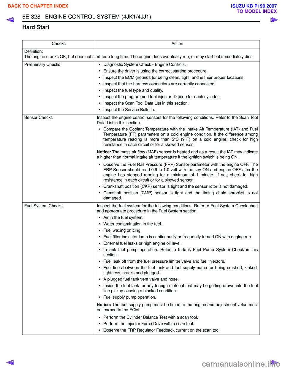
Hard Start
ChecksAction
Definition:
The engine cranks OK, but does not start for a long time. The engine does eventually run, or may start but immediately dies.
Preliminary Checks • Diagnostic System Check - Engine Controls.
• Ensure the driver is using the correct starting procedure.
• Inspect the ECM grounds for being clean, tight, and in their proper locations.
• Inspect that the harness connectors are correctly connected.
• Inspect the fuel type and quality.
• Inspect the programmed fuel injector ID code for each cylinder.
• Inspect the Scan Tool Data List in this section.
• Inspect the Service Bulletin.
Sensor Checks Inspect the engine control sensors for the following conditions. Refer to the Scan Tool
Data List in this section.
• Compare the Coolant Temperature with the Intake Air Temperature (IAT) and Fuel Temperature (FT) parameters on a cold engine condition. If the difference among
temperature reading is more than 5 °C (9 °F) on a cold engine, check for high
resistance in each circuit or for a skewed sensor.
Notice: The mass air flow (MAF) sensor is heated and as a result the IAT may indicate
a higher than normal intake air temperature if the ignition switch is being ON.
• Observe the Fuel Rail Pressure (FRP) Sensor parameter with the engine OFF. The FRP Sensor should read 0.9 to 1.0 volt with the key ON and engine OFF after the
engine has stopped running for a minimum of 1 minute. If not, check for high
resistance in each circuit or for a skewed sensor.
• Crankshaft position (CKP) sensor is tight and the sensor rotor is not damaged.
• Camshaft position (CMP) sensor is tight and the timing chain sprocket is not damaged.
Fuel System Checks Inspect the fuel system for the following conditions. Refer to Fuel System Check chart
and appropriate procedure in the Fuel System section.
• Air in the fuel system.
• Water contamination in the fuel.
• Fuel waxing or icing.
• Fuel filter indicator lamp is continuously or frequently turned ON with engine run.
• External fuel leaks or high engine oil level.
• In-tank fuel pump operation. Refer to In-tank Fuel Pump System Check in this section.
• Fuel leak off from the fuel pressure limiter valve and fuel injectors.
• Fuel lines between the fuel tank and fuel supply pump for being crushed, kinked, tightness, cracks and plugged.
• A plugged fuel tank vent valve and hose.
• Inside the fuel tank for any foreign material that may be getting drawn into the fuel line pickup causing a blocked condition.
• Fuel supply pump operation.
Notice: The fuel supply pump must be timed to the engine and adjustment value must
be learned to the ECM.
• Perform the Cylinder Balance Test with a scan tool.
• Perform the Injector Force Drive with a scan tool.
• Observe the FRP Regulator Feedback current on the scan tool.
BACK TO CHAPTER INDEX
TO MODEL INDEX
ISUZU KB P190 2007
Page 1947 of 6020
6E-330 ENGINE CONTROL SYSTEM (4JK1/4JJ1)
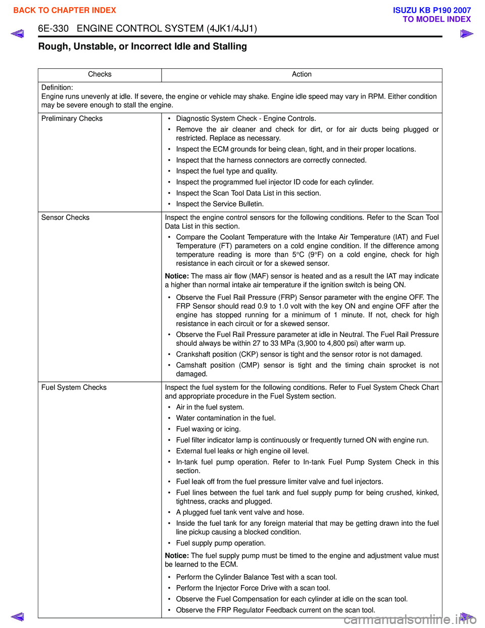
Rough, Unstable, or Incorrect Idle and Stalling
ChecksAction
Definition:
Engine runs unevenly at idle. If severe, the engine or vehicle may shake. Engine idle speed may vary in RPM. Either condition
may be severe enough to stall the engine.
Preliminary Checks • Diagnostic System Check - Engine Controls.
• Remove the air cleaner and check for dirt, or for air ducts being plugged or restricted. Replace as necessary.
• Inspect the ECM grounds for being clean, tight, and in their proper locations.
• Inspect that the harness connectors are correctly connected.
• Inspect the fuel type and quality.
• Inspect the programmed fuel injector ID code for each cylinder.
• Inspect the Scan Tool Data List in this section.
• Inspect the Service Bulletin.
Sensor Checks Inspect the engine control sensors for the following conditions. Refer to the Scan Tool
Data List in this section.
• Compare the Coolant Temperature with the Intake Air Temperature (IAT) and Fuel Temperature (FT) parameters on a cold engine condition. If the difference among
temperature reading is more than 5 °C (9 °F) on a cold engine, check for high
resistance in each circuit or for a skewed sensor.
Notice: The mass air flow (MAF) sensor is heated and as a result the IAT may indicate
a higher than normal intake air temperature if the ignition switch is being ON.
• Observe the Fuel Rail Pressure (FRP) Sensor parameter with the engine OFF. The FRP Sensor should read 0.9 to 1.0 volt with the key ON and engine OFF after the
engine has stopped running for a minimum of 1 minute. If not, check for high
resistance in each circuit or for a skewed sensor.
• Observe the Fuel Rail Pressure parameter at idle in Neutral. The Fuel Rail Pressure should always be within 27 to 33 MPa (3,900 to 4,800 psi) after warm up.
• Crankshaft position (CKP) sensor is tight and the sensor rotor is not damaged.
• Camshaft position (CMP) sensor is tight and the timing chain sprocket is not damaged.
Fuel System Checks Inspect the fuel system for the following conditions. Refer to Fuel System Check Chart
and appropriate procedure in the Fuel System section.
• Air in the fuel system.
• Water contamination in the fuel.
• Fuel waxing or icing.
• Fuel filter indicator lamp is continuously or frequently turned ON with engine run.
• External fuel leaks or high engine oil level.
• In-tank fuel pump operation. Refer to In-tank Fuel Pump System Check in this section.
• Fuel leak off from the fuel pressure limiter valve and fuel injectors.
• Fuel lines between the fuel tank and fuel supply pump for being crushed, kinked, tightness, cracks and plugged.
• A plugged fuel tank vent valve and hose.
• Inside the fuel tank for any foreign material that may be getting drawn into the fuel line pickup causing a blocked condition.
• Fuel supply pump operation.
Notice: The fuel supply pump must be timed to the engine and adjustment value must
be learned to the ECM.
• Perform the Cylinder Balance Test with a scan tool.
• Perform the Injector Force Drive with a scan tool.
• Observe the Fuel Compensation for each cylinder at idle on the scan tool.
• Observe the FRP Regulator Feedback current on the scan tool.
BACK TO CHAPTER INDEX
TO MODEL INDEX
ISUZU KB P190 2007
Page 1950 of 6020

ENGINE CONTROL SYSTEM (4JK1/4JJ1) 6E-333
Cuts Out
ChecksAction
Definition:
A constant jerking that follows the engine speed, usually more pronounced as the engine load increase. The exhaust has a
steady spitting sound at idle, low speed, or hard acceleration for the fuel starvation that can cause the engine to cut-out.
Preliminary Check • Diagnostic System Check - Engine Controls.
• Inspect that the harness connectors are correctly connected.
• Inspect the ECM grounds for being clean, tight, and in their proper locations.
• Inspect the Scan Tool Data List in this section.
• Inspect the Service Bulletin.
Sensor Checks Inspect the engine control sensors for the following conditions. Refer to the Scan Tool
Data List in this section.
• Observe the Mass Air Flow (MAF) parameter for a skewed or slow MAF sensor.
• Observe the Fuel Rail Pressure (FRP) Sensor parameter with the engine OFF. The FRP Sensor should read 0.9 to 1.0 volt with the key ON and engine OFF after the
engine has stopped running for a minimum of 1 minute. If not, check for high
resistance in each circuit or for a skewed sensor.
• Observe the Fuel Rail Pressure and Desired Fuel Rail Pressure parameter between idle and W.O.T. (accelerator pedal full travel) in Neutral. Fuel Rail Pressure
parameter should follow within ± 5 MPa ( ± 725 psi) quick enough.
• Observe the Accelerator Pedal Position (APP). APP parameter should change linearly from 0 to 100% according to the accelerator pedal operation.
• Crankshaft position (CKP) sensor is tight and the sensor rotor is not damaged.
Fuel System Checks Inspect the fuel system for the following conditions. Refer to Fuel System Check Chart
and appropriate procedure in the Fuel System section.
• Air in the fuel system.
• Water contamination in the fuel.
• Fuel waxing or icing.
• Fuel filter indicator lamp is continuously or frequently turned ON with engine run.
• In-tank fuel pump operation. Refer to In-tank Fuel Pump System Check in this section.
• Fuel leak off from the fuel pressure limiter valve and fuel injectors.
• Fuel lines between the fuel tank and fuel supply pump for being crushed, kinked, tightness, cracks and plugged.
• Inside the fuel tank for any foreign material that may be getting drawn into the fuel line pickup causing a blocked condition.
• Perform the Cylinder Balance Test with a scan tool.
• Perform the Injector Force Drive with a scan tool.
• Observe the Fuel Compensation for each cylinder at idle on the scan tool.
Air Intake System Checks Inspect the air intake system for the following conditions.
• Air cleaner, air intake ducts and charge air cooler for a restriction, holes, or leaks.
• A restriction in the turbocharger inlet duct.
• Intake throttle valve for a stuck condition.
• A restriction or leak in the intake manifold.
• A restriction or damaged at MAF sensor.
Exhaust System Checks Inspect the exhaust system for a possible restriction. Refer to the Exhaust System
section.
Additional Checks • Electromagnetic interference (EMI) on the reference circuit can cause an engine
miss condition. The scan tool can usually detect EMI by monitoring the engine
speed. A sudden increase in speed with little change in actual engine speed change
indicates that EMI is present. If a problem exists, check routing of high voltage
components, such as fuel injector solenoid valve wiring, near the sensor circuits.
BACK TO CHAPTER INDEX
TO MODEL INDEX
ISUZU KB P190 2007
Page 1951 of 6020

6E-334 ENGINE CONTROL SYSTEM (4JK1/4JJ1)
Surges
ChecksAction
Difinition:
The engine has a power variation under a steady throttle or cruise. The vehicle seems to speed up and slow down with no
change in the accelerator pedal.
Preliminary Checks • Diagnostic System Check - Engine Controls.
• Ensure the driver understands the A/C compressor operation.
• Use the scan tool in order to make sure the Vehicle Speed parameter reading matches the vehicle speedometer.
• Inspect the ECM grounds for being clean, tight, and in their proper locations.
• Inspect that the harness connectors are correctly connected.
• Inspect the fuel type and quality.
• Inspect the programmed fuel injector ID code for each cylinder.
• Inspect the Scan Tool Data List in this section.
• Inspect the Service Bulletin.
Sensor Checks Inspect the engine control sensors for the following conditions. Refer to the Scan Tool
Data List in this section.
• Observe the Mass Air Flow (MAF) parameter for a skewed or slow MAF sensor.
• Observe the Fuel Rail Pressure (FRP) Sensor parameter with the engine OFF. The FRP Sensor should read 0.9 to 1.0 volt with the key ON and engine OFF after the
engine has stopped running for a minimum of 1 minute. If not, check for high
resistance in each circuit or for a skewed sensor.
• Observe the Fuel Rail Pressure and Desired Fuel Rail Pressure parameter between idle and W.O.T. (accelerator pedal full travel) in Neutral. Fuel Rail Pressure
parameter should follow within ± 5 MPa ( ± 725 psi) quick enough.
• Observe the Accelerator Pedal Position (APP). APP parameter should change linearly from 0 to 100% according to the accelerator pedal operation.
Fuel System Checks Inspect the fuel system for the following conditions. Refer to Fuel System Check chart
and appropriate procedure in the Fuel System section.
• Air in the fuel system.
• Water contamination in the fuel.
• Fuel waxing or icing.
• Fuel filter indicator lamp is continuously or frequently turned ON with engine run.
• In-tank fuel pump operation. Refer to In-tank Fuel Pump System Check in this section.
• Fuel leak off from the fuel pressure limiter valve and fuel injectors.
• Fuel lines between the fuel tank and fuel supply pump for being crushed, kinked, tightness, cracks and plugged.
• A plugged fuel tank vent valve and hose.
• Inside the fuel tank for any foreign material that may be getting drawn into the fuel line pickup causing a blocked condition.
• Fuel supply pump operation.
Notice: The fuel supply pump must be timed to the engine and adjustment value must
be learned to the ECM.
• Perform the Cylinder Balance Test with a scan tool.
• Perform the Injector Force Drive with a scan tool.
BACK TO CHAPTER INDEX
TO MODEL INDEX
ISUZU KB P190 2007
Page 1979 of 6020

6E-362 ENGINE CONTROL SYSTEM (4JK1/4JJ1)
Fuel Supply Pump
The fuel supply pump is the heart of the common rail
type electronic fuel injection system. The fuel supply
pump is installed at the same location as the
conventional injection type pump, which spins at a 1 to
1 ratio of fuel supply pump to crankshaft speed. A fuel
rail pressure (FRP) regulator and fuel temperature
sensor are part of the fuel supply pump assembly.
Fuel is drawn from the fuel tank via the fuel supply
pump by the use of an internal feed pump (trochoid
type). This feed pump pumps fuel into a 2-plunger
chamber also internal to the fuel supply pump. Fuel into
this chamber is regulated by the FRP regulator solely
controlled by current supplied from the ECM. No
current to the solenoid results in maximum fuel flow
whereas full current to the solenoid produces no fuel
flow. As the engine spins, these two plungers produce
high pressure in the fuel rail. Since the ECM controls
the flow of fuel into this 2-plunger chamber, it therefore
controls the quantity and pressure of the fuel supply to
the fuel rail. This optimizes performance, improves
economy and reduces NOx emissions. Fuel Rail (Common Rail)
Legend
1. Pressure limiter valve
2. Fuel rail pressure (FRP) sensor
RTW76EMF000201
Suction pressure
Feed pressure
Return pressure
High pressure
Fuel rail
Injector
Delivery valve Cuction valve
Plunger
Fuel inletRegulation valve
Driveshaft
Fuel overflow
Feed pump
Return spring
Fuel tank Fuel filter
Return
SuctionFRP regulator
RTW76ESH002001
1
2
BACK TO CHAPTER INDEX
TO MODEL INDEX
ISUZU KB P190 2007
Page 2026 of 6020
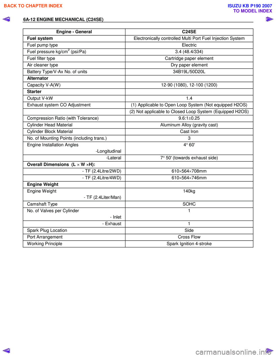
6A-12 ENGINE MECHANICAL (C24SE)
Engine - General C24SE
Fuel system Electronically controlled Multi Port Fuel Injection System
Fuel pump type Electric
Fuel pressure kg/cm2 (psi/Pa) 3.4 (48.4/334)
Fuel filter type Cartridge paper element
Air cleaner type Dry paper element
Battery Type/V-Ax No. of units 34B19L/50D20L
Alternator
Capacity V-A(W ) 12-90 (1080), 12-100 (1200)
Starter
Output V-kW 1.4
Exhaust system CO Adjustment (1) Applicable to Open Loop System (Not equipped H2OS)
(2) Not applicable to Closed Loop System (Equipped H2OS)
Compression Ratio (with Tolerance) 9.6:1±0.25
Cylinder Head Material Aluminum Alloy (gravity cast)
Cylinder Block Material Cast Iron
No. of Mounting Points (including trans.) 3
Engine Installation Angles
-Longitudinal 4
° 60'
-Lateral 7° 50' (towards exhaust side)
Overall Dimensions (L ×
××
×
W ×
××
×
H):
- TF (2.4Litre/2W D)610×564 ×708mm
- TF (2.4Litre/4W D) 610×564 ×746mm
Engine Weight
Engine W eight
- TF (2.4Liter/Man) 140kg
Camshaft Type
SOHC
No. of Valves per Cylinder
- Inlet1
- Exhaust
1
Spark Plug Location Side
Port Arrangement Cross Flow
W orking Principle Spark Ignition 4-stroke
BACK TO CHAPTER INDEX
TO MODEL INDEX
ISUZU KB P190 2007
Page 3235 of 6020
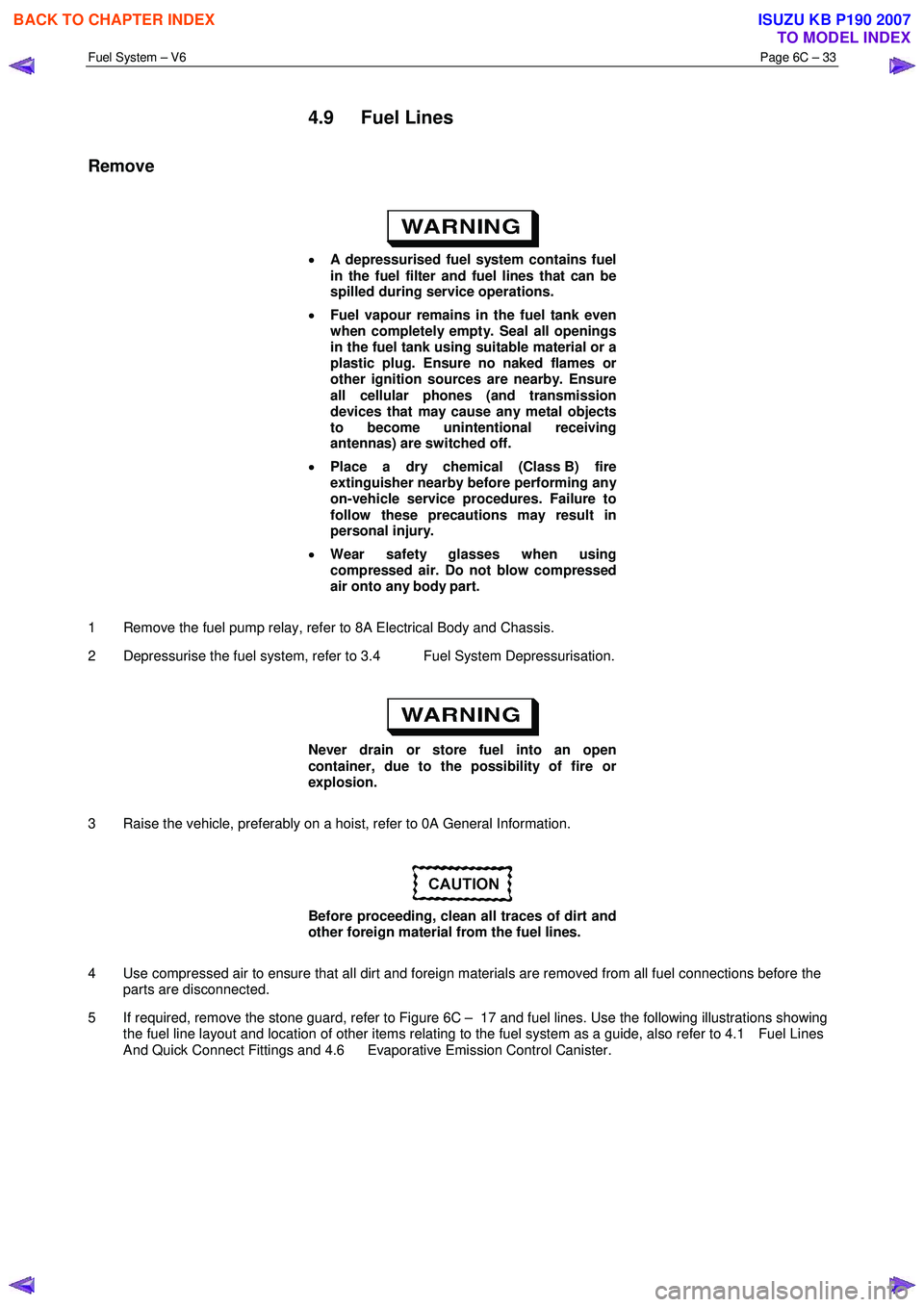
Fuel System – V6 Page 6C – 33
4.9 Fuel Lines
Remove
• A depressurised fuel system contains fuel
in the fuel filter and fuel lines that can be
spilled during service operations.
• Fuel vapour remains in the fuel tank even
when completely empty. Seal all openings
in the fuel tank using suitable material or a
plastic plug. Ensure no naked flames or
other ignition sources are nearby. Ensure
all cellular phones (and transmission
devices that may cause any metal objects
to become unintentional receiving
antennas) are switched off.
• Place a dry chemical (Class B) fire
extinguisher nearby before performing any
on-vehicle service procedures. Failure to
follow these precautions may result in
personal injury.
• Wear safety glasses when using
compressed air. Do not blow compressed
air onto any body part.
1 Remove the fuel pump relay, refer to 8A Electrical Body and Chassis.
2 Depressurise the fuel system, refer to 3.4 Fuel System Depressurisation.
Never drain or store fuel into an open
container, due to the possibility of fire or
explosion.
3 Raise the vehicle, preferably on a hoist, refer to 0A General Information.
Before proceeding, clean all traces of dirt and
other foreign material from the fuel lines.
4 Use compressed air to ensure that all dirt and foreign materials are removed from all fuel connections before the parts are disconnected.
5 If required, remove the stone guard, refer to Figure 6C – 17 and fuel lines. Use the following illustrations showing the fuel line layout and location of other items relating to the fuel system as a guide, also refer to 4.1 Fuel Lines
And Quick Connect Fittings and 4.6 Evaporative Emission Control Canister.
BACK TO CHAPTER INDEX
TO MODEL INDEX
ISUZU KB P190 2007
Page 3468 of 6020
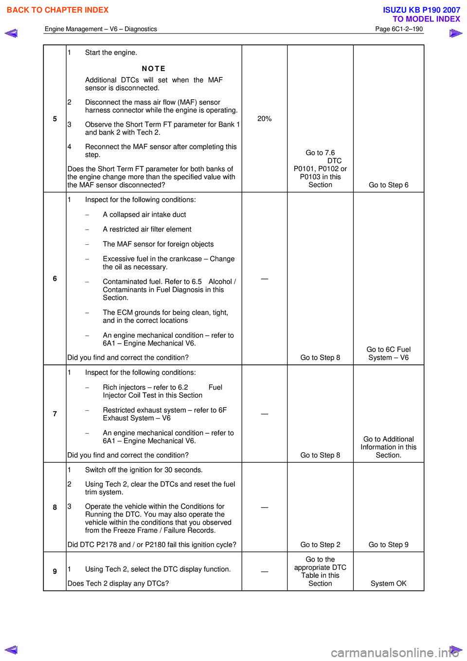
Engine Management – V6 – Diagnostics Page 6C1-2–190
5 1 Start the engine.
NOTE
Additional DTCs will set when the MAF
sensor is disconnected.
2 Disconnect the mass air flow (MAF) sensor harness connector while the engine is operating.
3 Observe the Short Term FT parameter for Bank 1 and bank 2 with Tech 2.
4 Reconnect the MAF sensor after completing this step.
Does the Short Term FT parameter for both banks of
the engine change more than the specified value with
the MAF sensor disconnected? 20%
Go to 7.6
DTC
P0101, P0102 or P0103 in this Section Go to Step 6
6 1 Inspect for the following conditions:
− A collapsed air intake duct
− A restricted air filter element
− The MAF sensor for foreign objects
− Excessive fuel in the crankcase – Change
the oil as necessary.
− Contaminated fuel. Refer to 6.5 Alcohol /
Contaminants in Fuel Diagnosis in this
Section.
− The ECM grounds for being clean, tight,
and in the correct locations
− An engine mechanical condition – refer to
6A1 – Engine Mechanical V6.
Did you find and correct the condition? —
Go to Step 8 Go to 6C Fuel
System – V6
7 1 Inspect for the following conditions:
− Rich injectors – refer to 6.2 Fuel
Injector Coil Test in this Section
− Restricted exhaust system – refer to 6F
Exhaust System – V6
− An engine mechanical condition – refer to
6A1 – Engine Mechanical V6.
Did you find and correct the condition? —
Go to Step 8 Go to Additional
Information in this Section.
8 1 Switch off the ignition for 30 seconds.
2 Using Tech 2, clear the DTCs and reset the fuel trim system.
3 Operate the vehicle within the Conditions for Running the DTC. You may also operate the
vehicle within the conditions that you observed
from the Freeze Frame / Failure Records.
Did DTC P2178 and / or P2180 fail this ignition cycle? —
Go to Step 2 Go to Step 9
9 1 Using Tech 2, select the DTC display function.
Does Tech 2 display any DTCs? —
Go to the
appropriate DTC Table in this Section System OK
BACK TO CHAPTER INDEX
TO MODEL INDEX
ISUZU KB P190 2007
Page 3474 of 6020

Engine Management – V6 – Diagnostics Page 6C1-2–196
3 1 Observe the Freeze Frame and / or the Failure
Records data for this DTC.
2 Turn the ignition OFF for 30 seconds.
3 Start the engine.
4 Operate the vehicle within the Conditions for Running the DTC. You may also operate the
vehicle within the conditions that you observed
from the Freeze Frame and / or the Failure
Records data.
Does the DTC fail this ignition cycle? —
Go to Step 4 Go to Additional
Information in this DTC.
4 Are both banks of the engine operating rich? —
Go to Step 5 Go to Step
5 1 Start the engine.
NOTE
Additional DTCs will set with the mass air
flow (MAF) sensor disconnected.
2 Disconnect the MAF sensor harness connector while the engine is operating.
3 Observe the Short Term FT parameter for Bank 1 and Bank 2 with Tech 2.
4 Connect the MAF sensor after completing this step.
Does the Short Term FT parameter for both banks of
the engine change more than the specified value with
the MAF sensor disconnected? 20%
Go to 7.6
DTC
P0101, P0102 or P0103 Go to Step 5
6 1 Inspect for the following conditions:
− A collapsed air intake duct
− A restricted air filter element
− Inspect the MAF sensor for foreign
objects.
− Excessive fuel in the crankcase – Change
the oil as necessary.
− Contaminated fuel. Refer to 6.5 Alcohol /
Contaminants in Fuel Diagnosisin this
Section.
− The engine control grounds for being
clean, tight, and in the correct locations
− An engine mechanical condition – refer to
6A1 – Engine Mechanical V6.
Did you find and correct the condition? —
Go to Step 8 Go to 6C Fuel
System – V6
7 1 Inspect for the following conditions:
− Rich injectors – Refer to 6.2 Fuel
Injector Coil Test in this Section
− Restricted exhaust system – Refer to 6F
Exhaust System – V6.
− An engine mechanical condition – refer to
6A1 – Engine Mechanical V6.
Did you find and correct the condition? —
Go to Step Go to Additional
Information in this DTC
BACK TO CHAPTER INDEX
TO MODEL INDEX
ISUZU KB P190 2007