license ISUZU KB P190 2007 Workshop Repair Manual
[x] Cancel search | Manufacturer: ISUZU, Model Year: 2007, Model line: KB P190, Model: ISUZU KB P190 2007Pages: 6020, PDF Size: 70.23 MB
Page 162 of 6020

2A-8 FRAME AND BUMPER
REAR STEP BUMPER
REMOVAL AND INSTALLATION
RTW 72ALF000401
Removal Steps
1. Rear step bumper assembly
2. Side step pad
3. License plate light
4. Rear bumper center pad
5. Extension harness
6. Center bar
7. Shell
8. Back bar / corner brace
9. Reinforcement assembly
Installation Steps
9. Reinforcement assembly
8. Back bar / corner brace
7. Shell
6. Center bar
5. Extension harness
4. Rear bumper center pad
3. License plate light
2. Side step pad
1. Rear step bumper assembly
BACK TO CHAPTER INDEX
TO MODEL INDEX
ISUZU KB P190 2007
Page 221 of 6020
2B-24 SHEET METAL
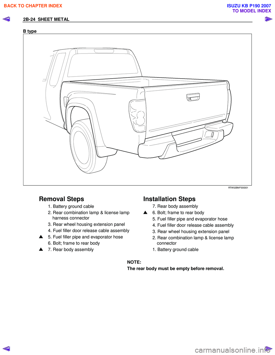
B type
RTW 52BMF000301
Removal Steps Installation Steps
1. Battery ground cable
2. Rear combination lamp & license lamp
harness connector
3. Rear wheel housing extension panel
4. Fuel filler door release cable assembly
5. Fuel filler pipe and evaporator hose
6. Bolt; frame to rear body
7. Rear body assembly
7. Rear body assembly
6. Bolt; frame to rear body
5. Fuel filler pipe and evaporator hose
4. Fuel filler door release cable assembly
3. Rear wheel housing extension panel
2. Rear combination lamp & license lamp
connector
1. Battery ground cable
NOTE:
The rear body must be empty before removal.
BACK TO CHAPTER INDEX
TO MODEL INDEX
ISUZU KB P190 2007
Page 1064 of 6020
6E-30 Engine Control System (4JH1)
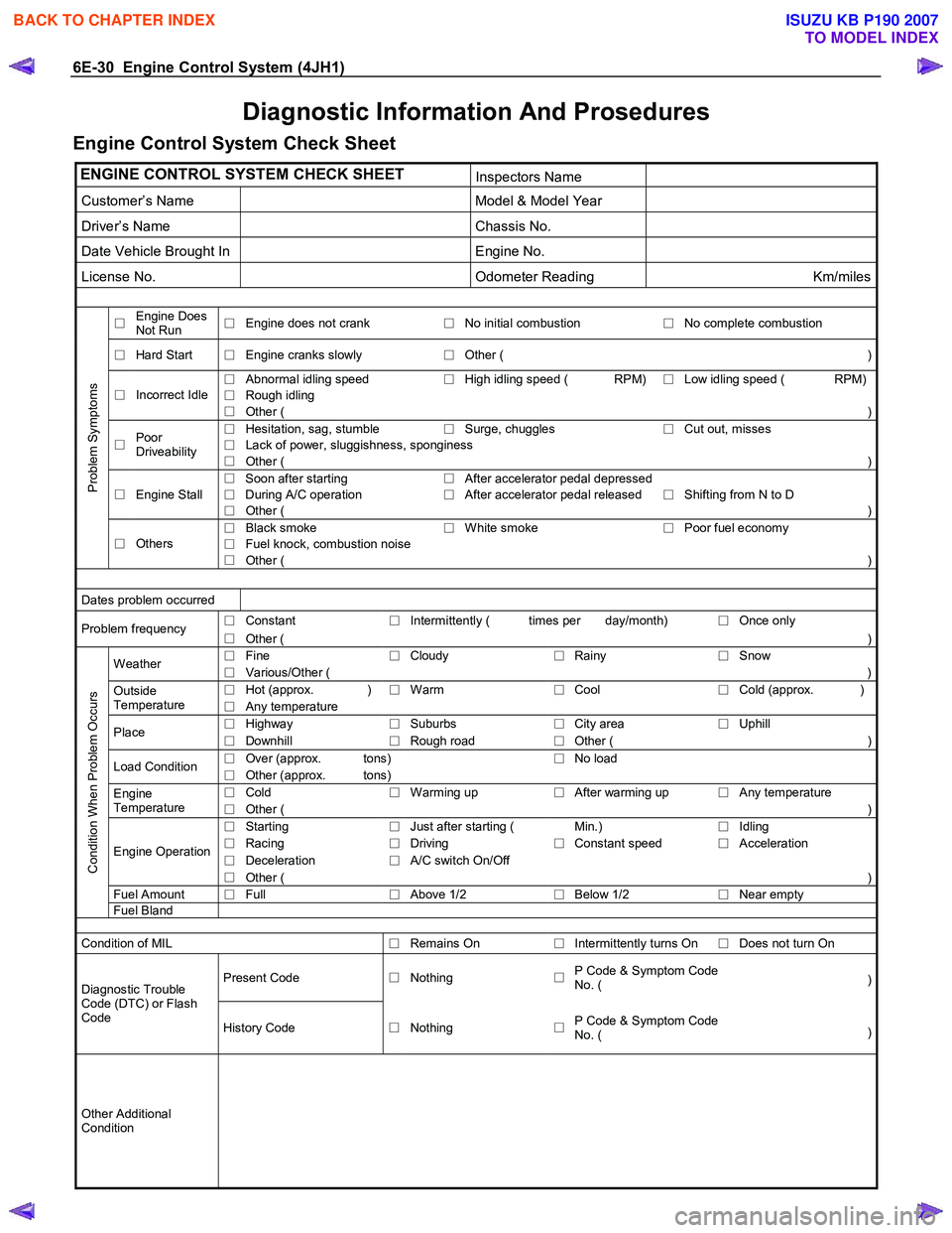
Diagnostic Information And Prosedures
Engine Control System Check Sheet
ENGINE CONTROL SYSTEM CHECK SHEET Inspectors Name
Customer’s Name Model & Model Year
Driver’s Name Chassis No.
Date Vehicle Brought In Engine No.
License No. Odometer Reading Km/miles
□ Engine Does
Not Run □
Engine does not crank
□No initial combustion
□ No complete combustion
□
Hard Start
□ Engine cranks slowly
□Other ( )
□
Abnormal idling speed
□High idling speed ( RPM)
□ Low idling speed ( RPM)
□
Rough idling □
Incorrect Idle
□ Other ( )
□
Hesitation, sag, stumble
□Surge, chuggles
□ Cut out, misses
□
Lack of power, sluggishness, sponginess □
Poor
Driveability □ Other ( )
□ Soon after starting
□After accelerator pedal depressed
Engine Stall
□ During A/C operation
□After accelerator pedal released
□ Shifting from N to D □
□ Other ( )
□
Black smoke
□White smoke
□ Poor fuel economy
□
Fuel knock, combustion noise
Problem Symptoms
□
Others
□ Other ( )
Dates problem occurred
□
Constant
□Intermittently ( times per day/month)
□ Once only Problem frequency
□ Other (
)
□ Fine
□Cloudy
□Rainy
□ Snow Weather
□ Various/Other (
)
□ Hot (approx. )
□Warm
□Cool
□ Cold (approx. )Outside
Temperature □ Any temperature
□
Highway
□Suburbs
□City area
□ Uphill Place
□ Downhill
□Rough road
□Other (
)
□ Over (approx. tons)
□No load
Load Condition
□ Other (approx. tons)
□ Cold
□Warming up
□After warming up
□ Any temperature Engine
Temperature □ Other ( )
□
Starting
□Just after starting ( Min.)
□ Idling
□
Racing
□Driving
□Constant speed
□ Acceleration
□
Deceleration
□A/C switch On/Off Engine Operation
□ Other ( )
Fuel Amount
□ Full
□Above 1/2
□Below 1/2
□ Near empty
Condition When Problem Occurs
Fuel
Bland
Condition of MIL
□Remains On
□Intermittently turns On
□ Does not turn On
Present Code
□Nothing
□P Code & Symptom Code
No. ( )Diagnostic Trouble
Code (DTC) or Flash
Code History Code □Nothing
□P Code & Symptom Code
No. ( )
Other Additional
Condition
BACK TO CHAPTER INDEX
TO MODEL INDEX
ISUZU KB P190 2007
Page 3198 of 6020
Engine Cooling – V6 Engine Page 6B1–63
4.5 Problems Not Requiring Disassembly of
Cooling System
1 Large obstructions blocking radiator or condenser airflow.
• Auxiliary oil coolers
• License plate
• Obstruction of radiator grille, for example, driving lights or mud
2 Loose, damaged or missing air chute side panels.
3 Missing or damaged air baffle.
4 Cracked or loose coolant recovery system hose.
5 Leaking heater component such as the heater core or water valve.
4.6 Problems Requiring Disassembly of Cooling System
1 Damaged cooling fan or faulty motor operation.
2 Pressure test cooling system.
3 Defective coolant pump.
• Eroded or broken impeller vanes
• Failed bearing or seal – check for shaft or bearing end play
4 Internally blocked radiator core.
5 Obstruction of coolant recovery system.
6 Internal system leaks.
• Head gaskets
• Cracked cylinder block
• Engine front cover
• Intake manifold gaskets
7 Blocked coolant passages in cylinder heads or block – remove cylinder heads and check.
4.7 Black Light and Dye Leak Diagnosis Method
It is strongly recommended that this diagnostic method be used to diagnose fluid leaks. This method is a proven and
reliable method that identifies the specific leak source.
The black light kit can be used for the leak detection of a number of fluids, when used with the appropriate tracer dye.
Examples are: Coolant, Engine Oil, Automatic Transmission Fluid and Air Conditioning Refrigerant (R134A).
The following is a summary of the steps involved in detecting a cooling system fluid leak using black light and dye:
1 Pour specified amount of dye into the cooling system via the coolant filler cap on the outlet housing. Refer 3.1 Service Notes in this Section.
2 Road test the vehicle under normal operating conditions.
3 Direct the light towards the suspect area. The fluid leak will appear as a brightly coloured path leading from the source.
4 Repair fluid leak and recheck to ensure that leak has been rectified.
5 Refer to the manufacturer’s directions when using this method.
BACK TO CHAPTER INDEX
TO MODEL INDEX
ISUZU KB P190 2007
Page 4963 of 6020
ELECTRICAL-BODY AND CHASSIS 8A-25
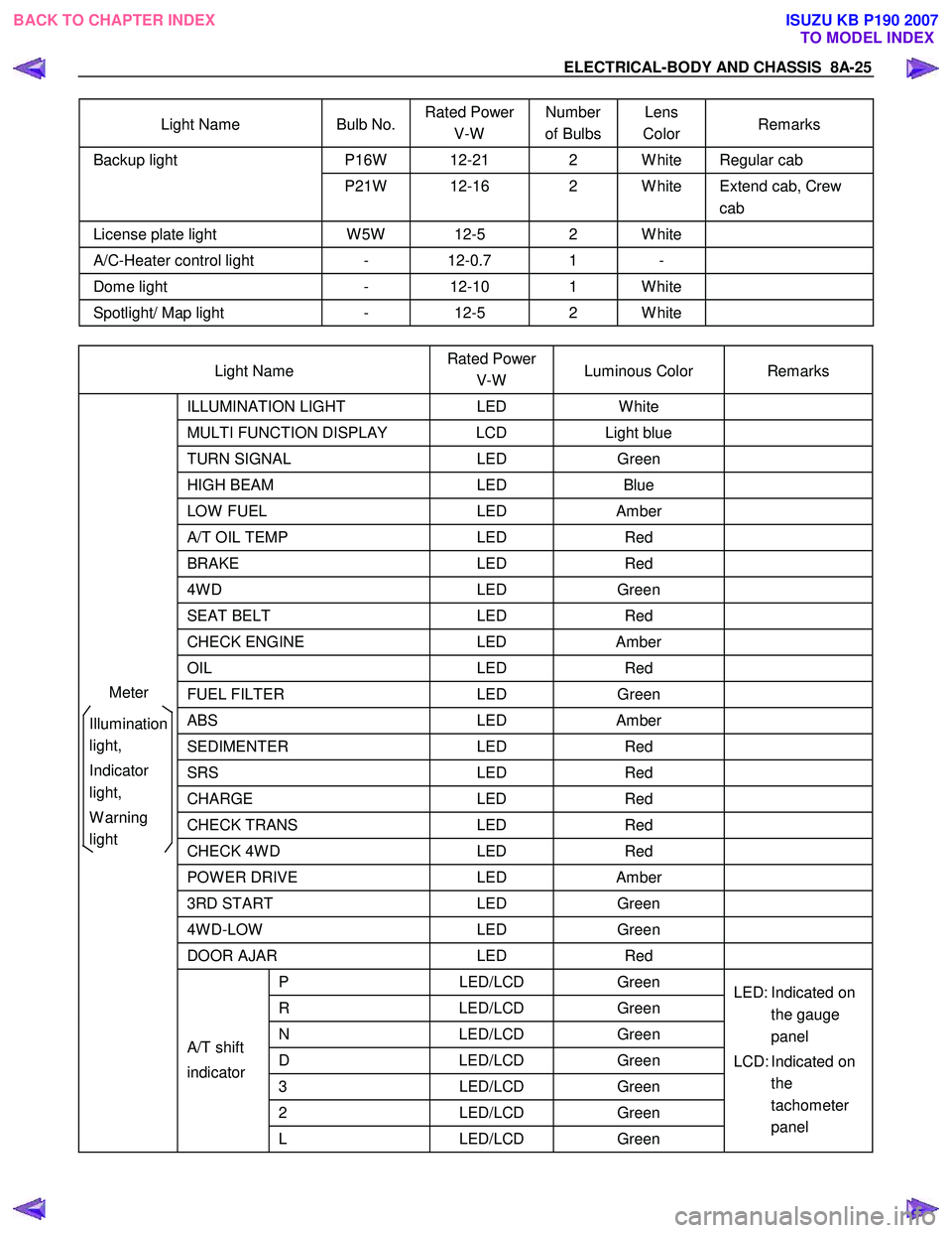
Light Name Bulb No. Rated Power
V-W Number
of Bulbs Lens
Color Remarks
P16W 12-21 2 W hite Regular cab Backup light
P21W 12-16 2 W hite Extend cab, Crew cab
License plate light W 5W 12-5 2 W hite
A/C-Heater control light - 12-0.7 1 -
Dome light - 12-10 1 W hite
Spotlight/ Map light - 12-5 2 W hite
Light Name Rated Power
V-W Luminous Color Remarks
ILLUMINATION
LIGHT LED W hite
MULTI FUNCTION DISPLAY LCD Light blue
TURN SIGNAL LED Green
HIGH BEAM LED Blue
LOW FUEL LED Amber
A/T OIL TEMP LED Red
BRAKE LED Red
4W D LED Green
SEAT BELT LED Red
CHECK ENGINE LED Amber
OIL LED Red
FUEL FILTER LED Green
ABS LED Amber
SEDIMENTER LED Red
SRS LED Red
CHARGE LED Red
CHECK TRANS LED Red
CHECK 4W D LED Red
POW ER DRIVE LED Amber
3RD START LED Green
4W D-LOW LED Green
DOOR AJAR LED Red
P LED/LCD Green
R LED/LCD Green
N LED/LCD Green
D LED/LCD Green
3 LED/LCD Green
2 LED/LCD Green
A/T shift
indicator
L LED/LCD Green LED: Indicated on
the gauge
panel
LCD: Indicated on the
tachometer
panel
Meter
Illumination
light,
Indicator
light,
W arning
light
BACK TO CHAPTER INDEX TO MODEL INDEXISUZU KB P190 2007
Page 5094 of 6020

8A-156 ELECTRICAL-BODY AND CHASSIS
CIRCUIT DIAGRAM HFV6 (CLEARANCE LIGHT, LICENSE PLATE LIGHT, TAIL LIGHT)
RTW 78AXF009601
BACK TO CHAPTER INDEX TO MODEL INDEXISUZU KB P190 2007
Page 5097 of 6020
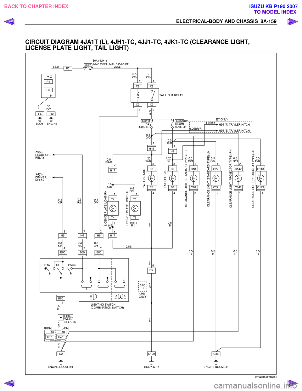
ELECTRICAL-BODY AND CHASSIS 8A-159
CIRCUIT DIAGRAM 4JA1T (L), 4JH1-TC, 4JJ1-TC, 4JK1-TC (CLEARANCE LIGHT,
LICENSE PLATE LIGHT, TAIL LIGHT)
RTW 78AXF026701
BACK TO CHAPTER INDEX TO MODEL INDEXISUZU KB P190 2007
Page 5102 of 6020

8A-164 ELECTRICAL-BODY AND CHASSIS
TAIL LIGHT, LICENSE PLATE LIGHT, CLEARANCE LIGHT
1. All lights do not light
Checkpoint Trouble Cause Countermeasure
Repair or replace the
combination switch
Lighting switch continuity
between connector
2
B60 - 1 B60
Poor switch point or connector
contact
NG
Reinstall or replace the tail
relay
Tail relay
Poor relay contact or relay
faulty
NG
OK
Reinstall or replace the fuse
No. EB12 (LH), EB11 (RH)
Fuse No. EB12 (LH) or EB11
(RH) (10A, Relay and fuse
box)
Poor fuse contact or blown
NG
OK
2. Tail light does not light
Replace the bulb or repair
connector contact
Tail light bulb continuity
Bulb burned out or poor
connector contact
NG
Repair open circuit or
connector contact
Continuity between connector
3
F5 - 4 F5 (RH)
or 3
F6 - 4 F6 (LH)
Open circuit or poor connector
contact
NG
OK
BACK TO CHAPTER INDEX
TO MODEL INDEXISUZU KB P190 2007
Page 5103 of 6020
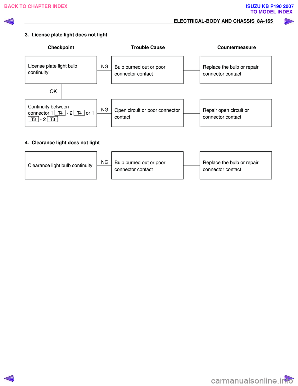
ELECTRICAL-BODY AND CHASSIS 8A-165
3. License plate light does not light
Checkpoint Trouble Cause Countermeasure
Repair open circuit or
connector contact
Continuity between
connector 1
T4 - 2 T4 or 1
T3 - 2 T3
Open circuit or poor connector
contact
NG
Replace the bulb or repair
connector contact
License plate light bulb
continuity
Bulb burned out or poor
connector contact
NG
OK
4. Clearance light does not light
Replace the bulb or repair
connector contactClearance light bulb continuityBulb burned out or poor
connector contact
NG
BACK TO CHAPTER INDEX TO MODEL INDEXISUZU KB P190 2007
Page 5110 of 6020

8A-172 ELECTRICAL-BODY AND CHASSIS
CLEARANCE LIGHT BULB (B type)
Removal
RTW 580SH000301
1. Remove the front combination light assembly.
• Refer to “FRONT COMBINATION LIGHT ASSEMBLY”
removal procedure in this section.
2. Turn the bulb counterclockwise to remove it. (Black socket side)
Installation
Follow the removal procedure in the reverse order to install the
clearance light.
Pay close attention to the important points mentioned in the
following paragraphs.
Connector
Be absolutely sure that the clearance light connector is
securely connected.
This will prevent a poor contact and an open circuit.
LICENSE PLATE LIGHT
Removal
1. Remove the lens cover 1 and the connector 2.
2. Pull the bulb
3 to remove it.
Installation
Follow the removal procedure in the reverse order to install the
license plate light.
Pay close attention to the important points mentioned in the
following paragraphs.
Bulb
Be absolutely sure that the license plate light bulb is correctly
installed.
This will prevent a poor contact and open circuit.
BACK TO CHAPTER INDEX TO MODEL INDEXISUZU KB P190 2007