ISUZU TFS SERIES 1997 Owner's Guide
TFS SERIES 1997
ISUZU
ISUZU
https://www.carmanualsonline.info/img/61/57182/w960_57182-0.png
ISUZU TFS SERIES 1997 Owner's Guide
Trending: steering wheel adjustment, length, air bleeding, clock setting, compression ratio, oil pressure, low oil pressure
Page 31 of 1600
REAR AXLE 4B-35
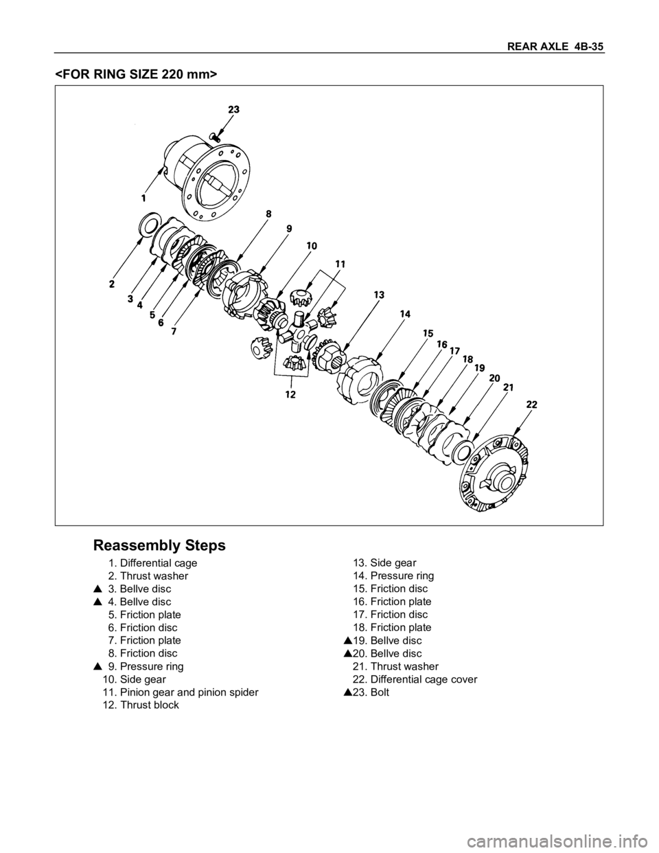
Reassembly Steps
1. Differential cage
2. Thrust washer
3. Bellve disc
4. Bellve disc
5. Friction plate
6. Friction disc
7. Friction plate
8. Friction disc
9. Pressure ring
10. Side gear
11. Pinion gear and pinion spider
12. Thrust block13. Side gear
14. Pressure ring
15. Friction disc
16. Friction plate
17. Friction disc
18. Friction plate
19. Bellve disc
20. Bellve disc
21. Thrust washer
22. Differential cage cover
23. Bolt
Page 32 of 1600

4B-36 REAR AXLE
Adjustment of Clearance between
Friction Disc and Plate
1) Measuring depth of differential case
mm(in)
Standard (A-B) 80.58 (3.17)
(C) 10.58 (0.41)
2) Measuring overall length of pressure ring, friction disc and
plate assembly
Assembly pinion shaft with pressure ring, then friction
disc and plate.
Measure length between plates at both ends over V-
shape groove. (D)
3) After A, B, C and D dimensions are measured, perform
adjustment with the following procedure.
Measure disc spring :
1.75 mm (0.69 in)
2 pcs (E)
Measure thickness of plate spring
Standard dimension :
1.75 mm (0.069 in)
2 pcs (F)
4) Select a friction disc or plate so that ((A-B+C) - (D+E+F) =
0.06 to 0.20 mm (0.002 to 0.008 in.) and also the difference
in total dimension of friction disc and plate, plate spring and
disc spring (left/right side) does not exceed 0.05 mm (0.002
in.).
Thickness : 1.75, 1.85 mm
Adjusting Backlash of Side Gear in Axial
Direction
1) Measuring depth of differential case
mm(in.)
Standard (F-B) 82.03 (3.23)
(G) 12.03 (0.47)
Page 33 of 1600
REAR AXLE 4B-37
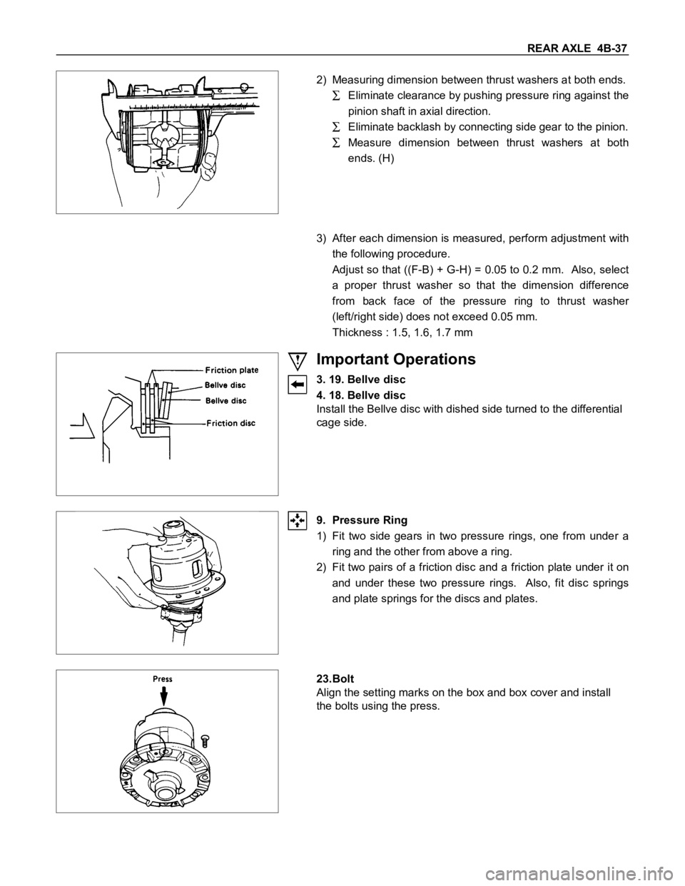
2) Measuring dimension between thrust washers at both ends.
Eliminate clearance by pushing pressure ring against the
pinion shaft in axial direction.
Eliminate backlash by connecting side gear to the pinion.
Measure dimension between thrust washers at both
ends. (H)
3) After each dimension is measured, perform adjustment with
the following procedure.
Adjust so that ((F-B) + G-H) = 0.05 to 0.2 mm. Also, select
a proper thrust washer so that the dimension difference
from back face of the pressure ring to thrust washer
(left/right side) does not exceed 0.05 mm.
Thickness : 1.5, 1.6, 1.7 mm
Important Operations
3. 19. Bellve disc
4. 18. Bellve disc
Install the Bellve disc with dished side turned to the differential
cage side.
9. Pressure Ring
1) Fit two side gears in two pressure rings, one from under a
ring and the other from above a ring.
2) Fit two pairs of a friction disc and a friction plate under it on
and under these two pressure rings. Also, fit disc springs
and plate springs for the discs and plates.
23.Bolt
Align the setting marks on the box and box cover and install
the bolts using the press.
Page 34 of 1600
4B-38 REAR AXLE
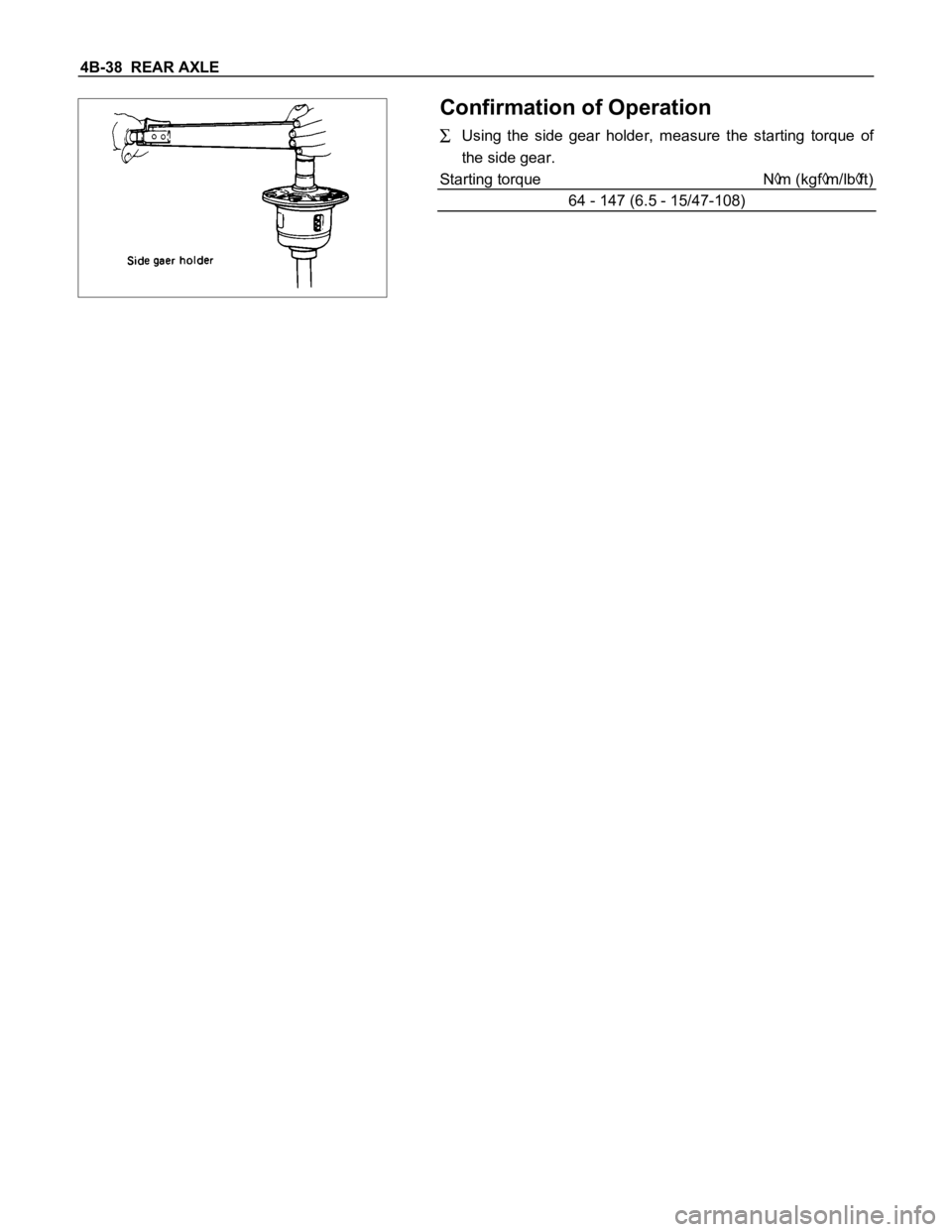
Confirmation of Operation
Using the side gear holder, measure the starting torque of
the side gear.
Starting torque N
m (kgfm/lbft)
64 - 147 (6.5 - 15/47-108)
Page 35 of 1600
REAR AXLE 4B-39
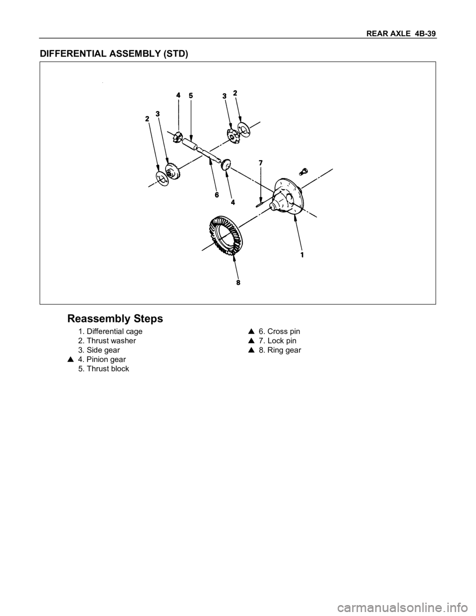
DIFFERENTIAL ASSEMBLY (STD)
Reassembly Steps
1. Differential cage
2. Thrust washer
3. Side gear
4. Pinion gear
5. Thrust block
6. Cross pin
7. Lock pin
8. Ring gear
Page 36 of 1600
4B-40 REAR AXLE
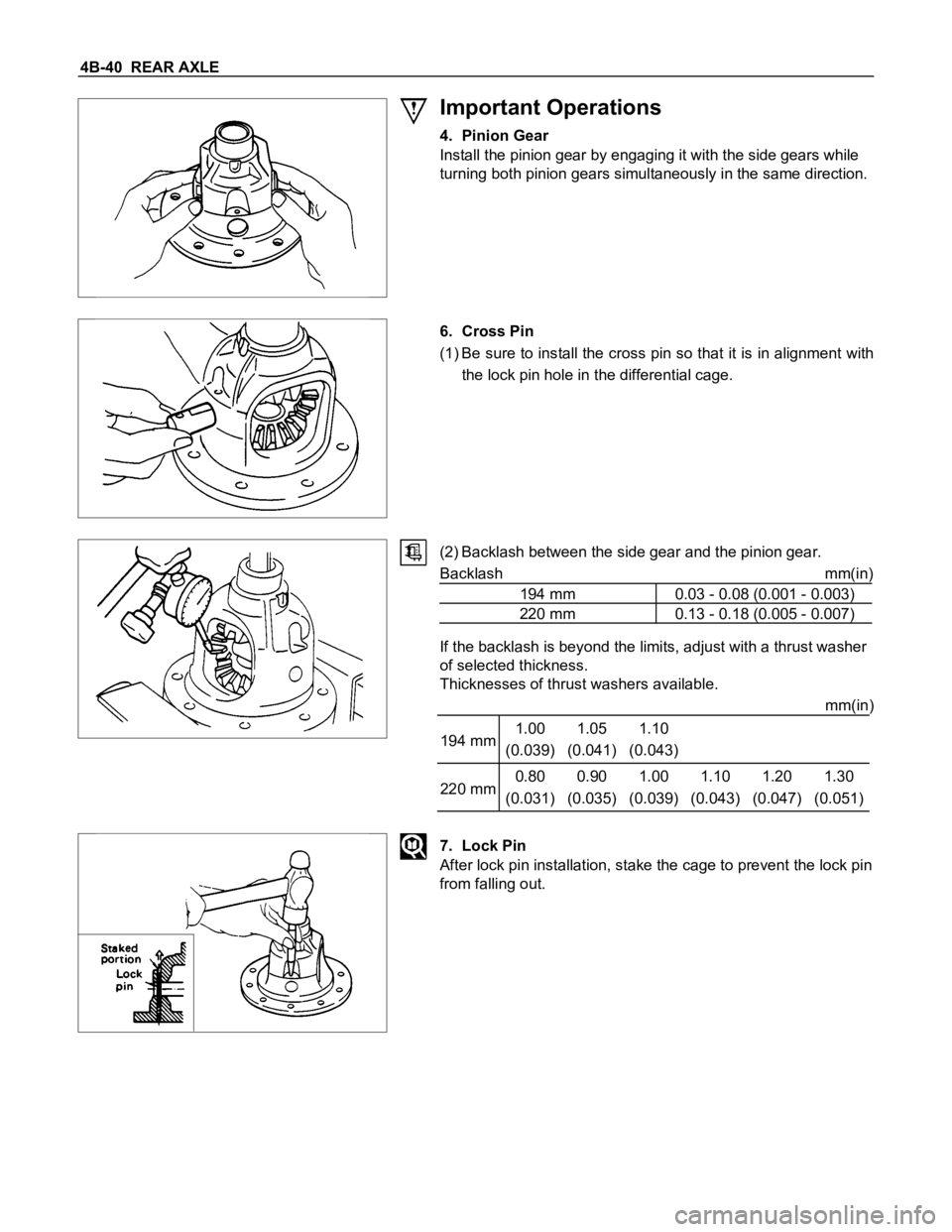
Important Operations
4. Pinion Gear
Install the pinion gear by engaging it with the side gears while
turning both pinion gears simultaneously in the same direction.
6. Cross Pin
(1) Be sure to install the cross pin so that it is in alignment with
the lock pin hole in the differential cage.
(2) Backlash between the side gear and the pinion gear.
Backlash mm(in)
194 mm 0.03 - 0.08 (0.001 - 0.003)
220 mm 0.13 - 0.18 (0.005 - 0.007)
If the backlash is beyond the limits, adjust with a thrust washer
of selected thickness.
Thicknesses of thrust washers available.
mm(in)
194 mm1.00
(0.039)1.05
(0.041)1.10
(0.043)
220 mm0.80
(0.031)0.90
(0.035)1.00
(0.039)1.10
(0.043)1.20
(0.047)1.30
(0.051)
7. Lock Pin
After lock pin installation, stake the cage to prevent the lock pin
from falling out.
Page 37 of 1600
REAR AXLE 4B-41
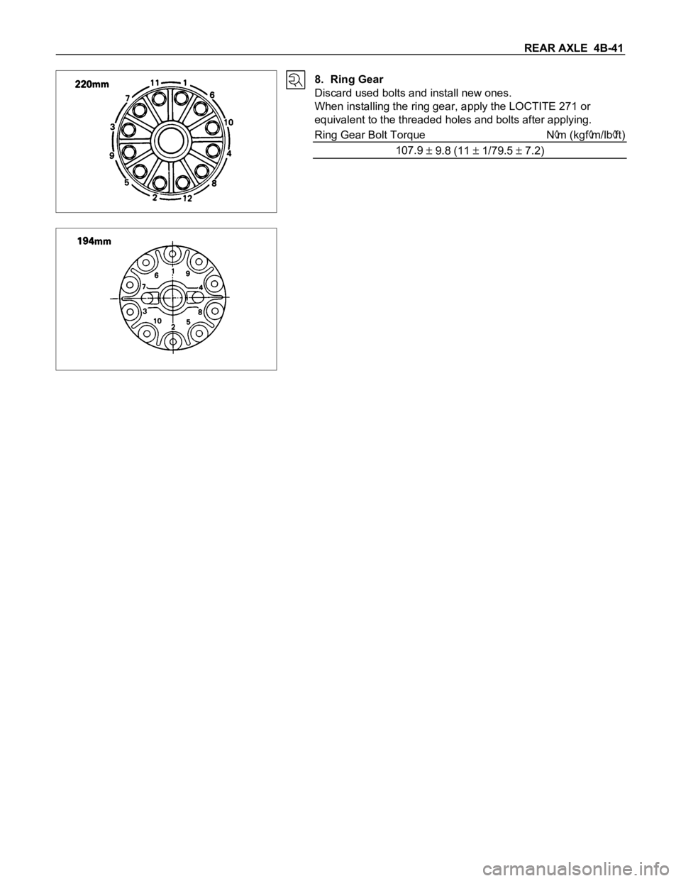
8. Ring Gear
Discard used bolts and install new ones.
When installing the ring gear, apply the LOCTITE 271 or
equivalent to the threaded holes and bolts after applying.
Ring Gear Bolt Torque N
m (kgfm/lbft)
107.9
9.8 (11 1/79.5 7.2)
Page 38 of 1600
4B-42 REAR AXLE
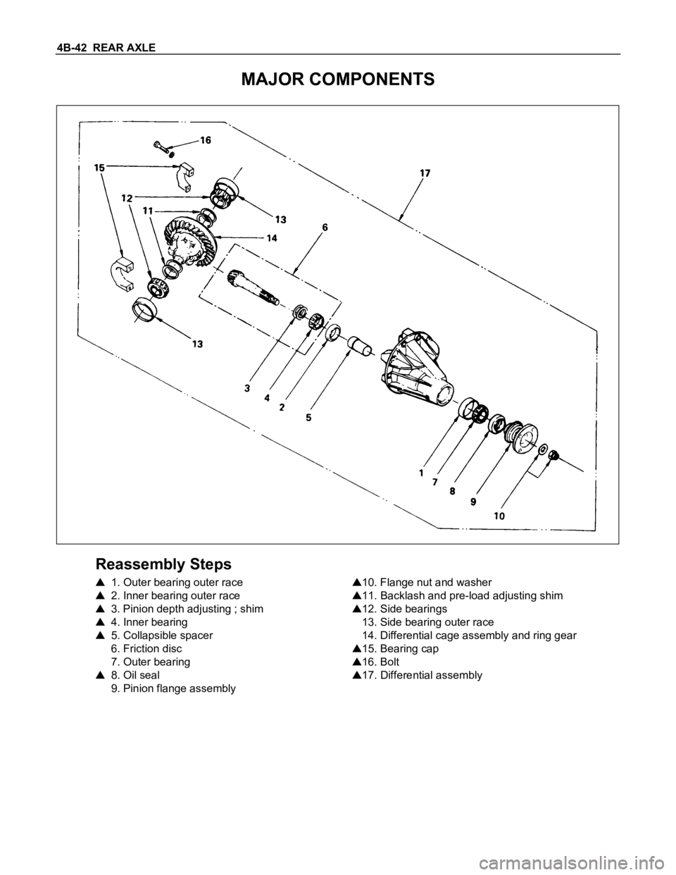
MAJOR COMPONENTS
Reassembly Steps
1. Outer bearing outer race
2. Inner bearing outer race
3. Pinion depth adjusting ; shim
4. Inner bearing
5. Collapsible spacer
6. Friction disc
7. Outer bearing
8. Oil seal
9. Pinion flange assembly
10. Flange nut and washer
11. Backlash and pre-load adjusting shim
12. Side bearings
13. Side bearing outer race
14. Differential cage assembly and ring gear
15. Bearing cap
16. Bolt
17. Differential assembly
Page 39 of 1600
REAR AXLE 4B-43
Important Operations
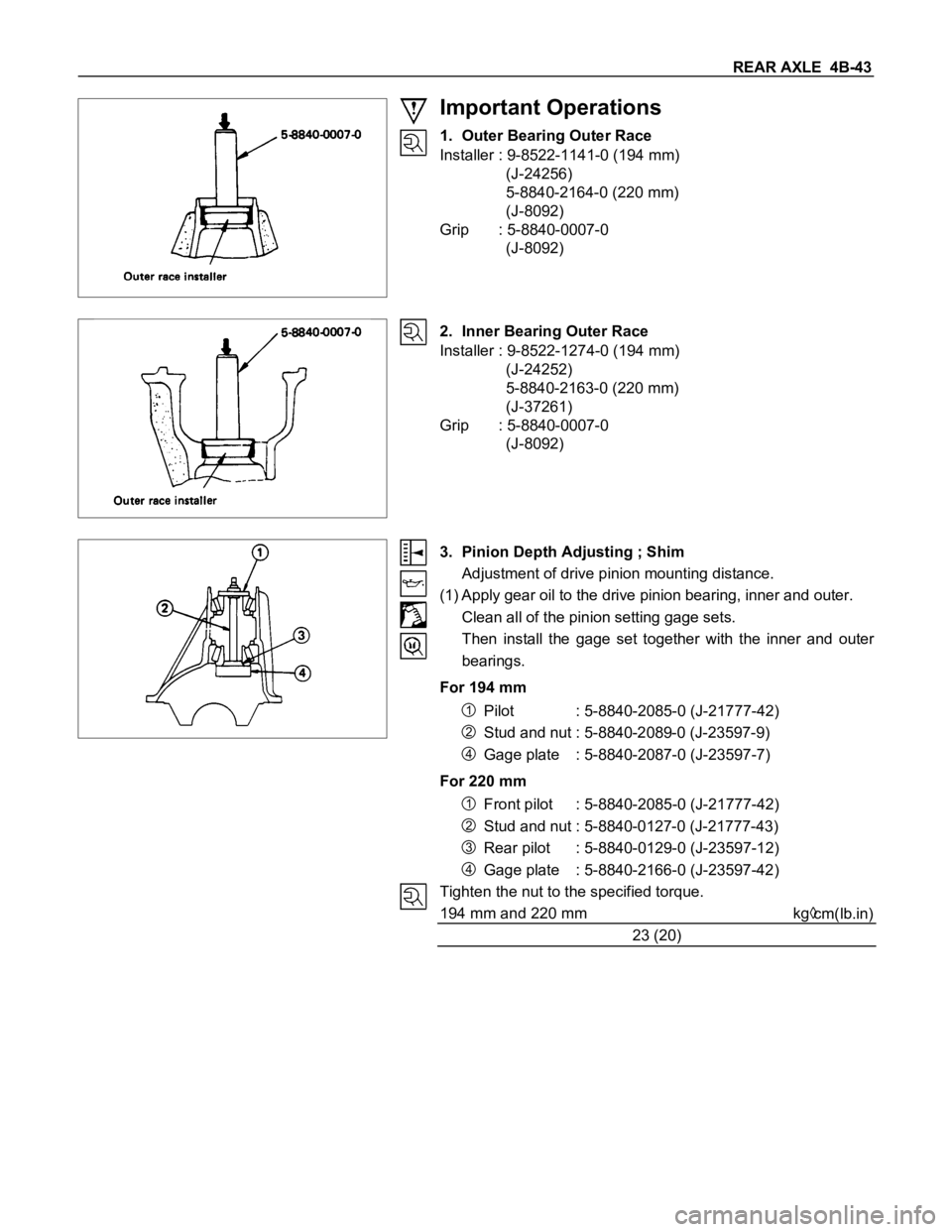
1. Outer Bearing Outer Race
Installer : 9-8522-1141-0 (194 mm)
(J-24256)
5-8840-2164-0 (220 mm)
(J-8092)
Grip : 5-8840-0007-0
(J-8092)
2. Inner Bearing Outer Race
Installer : 9-8522-1274-0 (194 mm)
(J-24252)
5-8840-2163-0 (220 mm)
(J-37261)
Grip : 5-8840-0007-0
(J-8092)
3. Pinion Depth Adjusting ; Shim
Adjustment of drive pinion mounting distance.
(1) Apply gear oil to the drive pinion bearing, inner and outer.
Clean all of the pinion setting gage sets.
Then install the gage set together with the inner and outer
bearings.
For 194 mm
1Pilot : 5-8840-2085-0 (J-21777-42)
2Stud and nut : 5-8840-2089-0 (J-23597-9)
4Gage plate : 5-8840-2087-0 (J-23597-7)
For 220 mm
1Front pilot : 5-8840-2085-0 (J-21777-42)
2Stud and nut : 5-8840-0127-0 (J-21777-43)
3Rear pilot : 5-8840-0129-0 (J-23597-12)
4Gage plate : 5-8840-2166-0 (J-23597-42)
Tighten the nut to the specified torque.
194 mm and 220 mm kg
cm(lb.in)
23 (20)
Page 40 of 1600
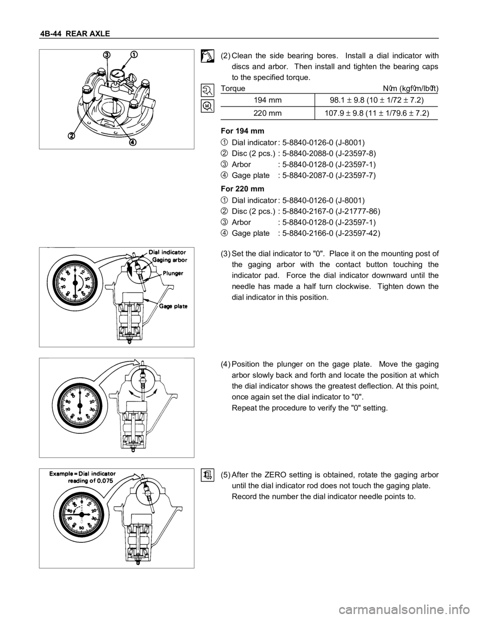
4B-44 REAR AXLE
(2) Clean the side bearing bores. Install a dial indicator with
discs and arbor. Then install and tighten the bearing caps
to the specified torque.
Torque N
m (kgfm/lbft)
194 mm 98.1
9.8 (10 1/72 7.2)
220 mm 107.9 9.8 (11 1/79.6 7.2)
For 194 mm
1Dial indicator : 5-8840-0126-0 (J-8001)
2Disc (2 pcs.) : 5-8840-2088-0 (J-23597-8)
3Arbor : 5-8840-0128-0 (J-23597-1)
4Gage plate : 5-8840-2087-0 (J-23597-7)
For 220 mm
1Dial indicator : 5-8840-0126-0 (J-8001)
2Disc (2 pcs.) : 5-8840-2167-0 (J-21777-86)
3Arbor : 5-8840-0128-0 (J-23597-1)
4Gage plate : 5-8840-2166-0 (J-23597-42)
(3) Set the dial indicator to "0". Place it on the mounting post of
the gaging arbor with the contact button touching the
indicator pad. Force the dial indicator downward until the
needle has made a half turn clockwise. Tighten down the
dial indicator in this position.
(4) Position the plunger on the gage plate. Move the gaging
arbor slowly back and forth and locate the position at which
the dial indicator shows the greatest deflection. At this point,
once again set the dial indicator to "0".
Repeat the procedure to verify the "0" setting.
(5) After the ZERO setting is obtained, rotate the gaging arbor
until the dial indicator rod does not touch the gaging plate.
Record the number the dial indicator needle points to.
Trending: remote control, drain bolt, check engine light, clock setting, transmission oil, tire type, wheel alignment
