ISUZU TFS SERIES 1997 Manual PDF
TFS SERIES 1997
ISUZU
ISUZU
https://www.carmanualsonline.info/img/61/57182/w960_57182-0.png
ISUZU TFS SERIES 1997 Manual PDF
Trending: dashboard, clutch, brake pads, change wheel, bolt pattern, instrument panel, remote control
Page 71 of 1600
4C1-8 FRONT WHEEL DRIVE
SERVICING
Hub Bearing Preload at the Wheel Pin
44 Model kg(lb)
New bearing and New oil seal 2 - 2.5 (4.4 - 5.5)
Reuse bearing and New oil seal 1.2 - 1.8 (2.6 - 4.0)
42 Model kg(lb)
New bearing and New oil seal 0.8 - 1.0 (1.8 - 2.2)
Reuse bearing and New oil seal 0.8 - 1.0 (1.8 - 2.2)
Page 72 of 1600
FRONT WHEEL DRIVE 4C1-9
GENERAL DESCRIPTION
FRONT DRIVE AXLE
FRONT HUB AND DISC (42 model)
Page 73 of 1600
4C1-10 FRONT WHEEL DRIVE
FRONT HUB AND DISC (44 model)
Page 74 of 1600
FRONT WHEEL DRIVE 4C1-11
LOCKING HUB
AUTOMATIC TYPE MANUAL TYPE
FRONT PROPELLER SHAFT
Page 75 of 1600
4C1-12 FRONT WHEEL DRIVE
FRONT DRIVE AXLE ASSEMBLY
REMOVAL AND INSTALLATION
1. Refer to SECTION 3E “WHEEL AND TIRES” for road wheel Disassembly and Reassembly procedure.
2. Refer to SECTION 4 “BRAKES” for disc brake caliper removal and installation procedure.
3. Refer to SECTION 3B “STEERING” for Steering linkage removal and installation procedure.
4. Refer to SECTION 4C “FRONT WHEEL DRIVE” for automatic hub disassembly and reassembly procedure.
Removal Steps
1. Assembly of hub and disc, back plate,
knuckle, knuckle arm, and lower end.
2. Propeller shaft
3. Nut and bolt
4. Washer
5. Front drive axle assembly
6. Washer
Installation Steps
6. Washer
5. Front drive axle assembly
4. Washer
3. Nut and bolt
2. Propeller shaft
1. Assembly of hub and disc, back plate,
knuckle, knuckle arm, and lower end.
Page 76 of 1600
FRONT WHEEL DRIVE 4C1-13
Important Operations - Removal
1. Assembly of hub and disc, back plate, knuckle, knuckle
arm, and lower end.
Before removal, jack up the front of vehicle and support the
frame with jack stands.
2. Propeller Shaft
Apply the setting marks.
5. Front Drive Axle Assembly
(1) Put the lifting jack under the center part of the front.
(2) Remove four bolts fixing axle case mounting brackets to the
frame.
Note :
Be careful not to damage birfield joints or double off-set
joints when supporting axle shaft assembly.
(3) Lower the front axle assembly and roll it out toward the front
of the vehicle.
Take care not to damage the birfield joints or the double off-
set joints.
Page 77 of 1600
4C1-14 FRONT WHEEL DRIVE
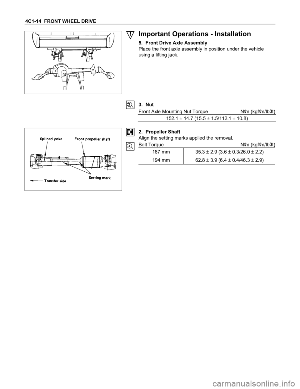
Important Operations - Installation
5. Front Drive Axle Assembly
Place the front axle assembly in position under the vehicle
using a lifting jack.
3. Nut
Front Axle Mounting Nut Torque N
m (kgfm/lbft)
152.1
14.7 (15.5 1.5/112.1 10.8)
2. Propeller Shaft
Align the setting marks applied the removal.
Bolt Torque N
m (kgfm/lbft)
167 mm 35.3
2.9 (3.6 0.3/26.0 2.2)
194 mm 62.8 3.9 (6.4 0.4/46.3 2.9)
Page 78 of 1600
FRONT WHEEL DRIVE 4C1-15
DISASSEMBLY
Disassembly Steps
1. Band
2. Bellows
3. Circlip
4. BJ shaft assembly
5. Ball
6. Snap ring
7. Ball retainer
8. Ball guide
9. Band
10. Bellows
11. Dust seal12. BJ shaft
13. Bolt
14. DOJ case assembly
15. Snap ring
16. Bearing
17. Snap ring
18. O-ring
19. Oil seal
20. Bracket
21. DOJ case
22. Axle case and differential
Page 79 of 1600
4C1-16 FRONT WHEEL DRIVE
Important Operations
1. Band
Raise the hooked end of the band with a screwdriver or
equivalent.
3. Circlip
Pry off with a screwdriver or equivalent.
5. Ball
Remove the six balls with a screwdriver or equivalent.
Rotate the case half a pitch to align the ball guide on the case
with the projected portion of the ball retainer, then slide the
case toward the bellows. The case can not be removed in the
reverse direction.
6. Snap Ring
Remove the snap ring fastening the ball retainer to the center
shaft.
Page 80 of 1600
FRONT WHEEL DRIVE 4C1-17
8. Band
Raise the hooked end of the band with a screwdriver or
equivalent.
Trending: oil capacity, stop start, engine, wheel torque, spare wheel, dashboard, center console


