lock ISUZU TFS SERIES 1997 Manual Online
[x] Cancel search | Manufacturer: ISUZU, Model Year: 1997, Model line: TFS SERIES, Model: ISUZU TFS SERIES 1997Pages: 1600, PDF Size: 40.98 MB
Page 512 of 1600

CAB 10-15
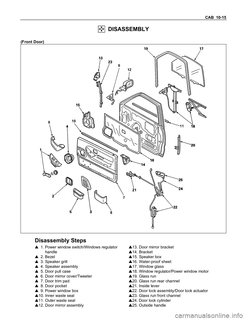
DISASSEMBLY
(Front Door)
87 910
11 6
Disassembly Steps
1. Power window switch/Windows regulator
handle
2. Bezel
3. Speaker grill
4. Speaker assembly
5. Door pull case
6. Door mirror cover/Tweeter
7. Door trim pad
8. Door pocket
9. Power window box
10. Inner waste seal
11. Outer waste seal
12. Door mirror assembly
13. Door mirror bracket
14. Bracket
15. Speaker box
16. Water-proof sheet
17. Window glass
18. Window regulator/Power window motor
19. Glass run
20. Glass run rear channel
21. Inside lever
22. Door lock assembly/Door lock actuator
23. Glass run front channel
24. Door lock cylinder
25. Outside handle
Page 515 of 1600

10-18 CAB
17.Window Glass
Remove 2 screws through the access hole and pull out
the window glass upward.
18.Window Regulator/Power Window Motor
Disconnect the power window motor connector.
19.Glass Run
Pull it out of the door piller of the channel. (front/rear)
20.Glass Run Rear Channel
Remove 2 screws.
21.Inside Lever
22.Door Lock Assembly/Door Lock Actuator
Disconnect the linkage with the outside handle, the
inside lever and the lock cylinder.
23.Glass Run Front Channel
24.Door Lock Cylinder
Remove the door lock cylinder by applying finger
pressure from inside while depressing the retaining clip.
25.Outside Handle
Page 516 of 1600

CAB 10-19
DISASSEMBLY AND REASSEMBLY
(Rear Door)
3
2
910 181219 13
1716
15 14
6
5 4 1611
7
68
Disassembly Steps
1.Power window switch/Window regurator
handle
2. Speaker grill
3. Speaker
4. Bezel
5. Inside pull handole
6. Door trim pad
7. Arm rest sm
8. Bracket
9. Water proof sheet
10. Glass guide
11. Upper cover
12. Window regurator/Power window motor
13. Window glass
14. Bracket15. Inside lever
16. Outside handle
17. Door lock cylinder
18. Outer waste seal
19. Glass run
Reassembly Steps
To reassemble, follow the disassembly steps
in the reverse order.
Page 518 of 1600

CAB 10-21
13.Window Glass
First, align the height of regulator to the access hole.
Remove 2 screws attaching bottom channel and
regulator, then remove the glass.
Remove the window glass by tilting it as necessary.
17.Door Lock Assembly
Disconnect the linkage from the door outside handle,
inside lever and lock cylinder.
Remove the 2 bolts holding the outside handle from
inner side.
Remove the 3 bolts holding the door lock assembly.
Page 520 of 1600

CAB 10-23
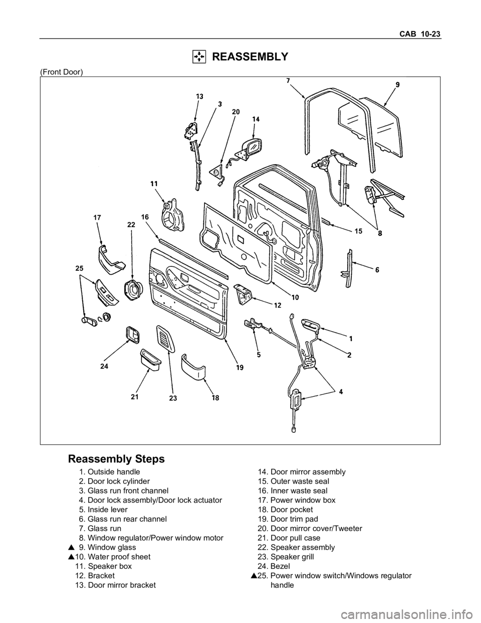
REASSEMBLY
(Front Door)
15
23 21 24 2522 171620
Reassembly Steps
1. Outside handle
2. Door lock cylinder
3. Glass run front channel
4. Door lock assembly/Door lock actuator
5. Inside lever
6. Glass run rear channel
7. Glass run
8. Window regulator/Power window motor
9. Window glass
10. Water proof sheet
11. Speaker box
12. Bracket
13. Door mirror bracket14. Door mirror assembly
15. Outer waste seal
16. Inner waste seal
17. Power window box
18. Door pocket
19. Door trim pad
20. Door mirror cover/Tweeter
21. Door pull case
22. Speaker assembly
23. Speaker grill
24. Bezel
25. Power window switch/Windows regulator
handle
Page 543 of 1600

CLUTCH 7C-3
GENERAL DESCRIPTION
HYDRAULIC CONTROL TYPE
HEC Engine Series4J Engine Series
6VD1
The clutch assembly consists of the pressure plate, the clutch cover, the diaphragm spring pivot pin and the driven
plate assembly.
The clutch pedal is connected to the shift block through the clutch shaft and the shift fork.
The driven plate assembly is installed between the flywheel and the pressure plate.
Diaphragm spring pressure holds the driven plate against flywheel and the pressure plate to provide the friction
necessary to engage the clutch.
Depressing the clutch pedal moves the shift fork against the shift block.
The shift block forces the release bearing against the diaphragm to overcome the force of the diaphragm spring and
separate the driven plate from the flywheel and pressure plate to disengage the clutch.
Except 6VD1 (3.2L) engine model, the conventional push-type clutch is used.
For 6VD1 (3.2L) engine model, the pull-type clutch is employed. The pull-type clutch is disengaged by pulling the
release lever (release bearing) to disengage the pressure plate.
Page 553 of 1600

CLUTCH 7C-13
SERVICING
Servicing refers to general maintenance procedures to be performed by qualified service personnel.
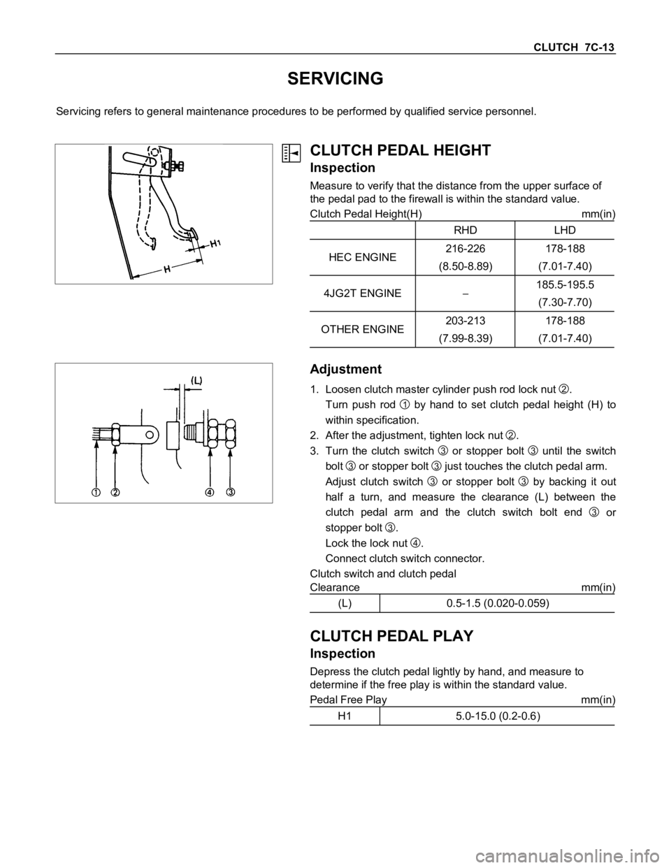
CLUTCH PEDAL HEIGHT
Inspection
Measure to verify that the distance from the upper surface of
the pedal pad to the firewall is within the standard value.
Clutch Pedal Height(H) mm(in)
RHD LHD
HEC ENGINE216-226
(8.50-8.89)178-188
(7.01-7.40)
4JG2T ENGINE185.5-195.5
(7.30-7.70)
OTHER ENGINE203-213
(7.99-8.39)178-188
(7.01-7.40)
Adjustment
1. Loosen clutch master cylinder push rod lock nut
2.
Turn push rod
1 by hand to set clutch pedal height (H) to
within specification.
2. After the adjustment, tighten lock nut
2.
3. Turn the clutch switch
3 or stopper bolt
3 until the switch
bolt
3 or stopper bolt
3 just touches the clutch pedal arm.
Adjust clutch switch
3 or stopper bolt
3 by backing it out
half a turn, and measure the clearance (L) between the
clutch pedal arm and the clutch switch bolt end
3 or
stopper bolt
3.
Lock the lock nut
4.
Connect clutch switch connector.
Clutch switch and clutch pedal
Clearance mm(in)
(L) 0.5-1.5 (0.020-0.059)
CLUTCH PEDAL PLAY
Inspection
Depress the clutch pedal lightly by hand, and measure to
determine if the free play is within the standard value.
Pedal Free Play mm(in)
H1 5.0-15.0 (0.2-0.6)
Page 563 of 1600

CLUTCH 7C-23
Release Bearing Replacement
Removal (Except 6VD1)
Use the bearing puller and the adapter to remove the release
bearing.
Bearing Puller : 5-8840-0013-0 (J-22888)
Adapter : 5-8840-0124-0 (J-2241-11)
Release Bearing Installation (Except 6VD1)
1. Set the release bearing to the shift block bearing fitting
surfaces.
The release bearing must be perfectly horizontal.
2. Use a bench press to fit the release bearing to the shift
block.
Install the parts as illustrated after applying wheel bearing
grease or multi-purpose type grease (NLGI No.2 or No.3).
6VD1Release Bearing (6VD1)
1. Visually check the release bearing for excessive play, noise
and breakage.
If any of these conditions are discovered, the release
bearing must be replaced.
6VD1NOTE:
When replacing the release bearing, replace both the
wedge collar and wire ring at the same time.
Page 564 of 1600

7C-24 CLUTCH
Wedge Collar (6VD1)
1. Visually check the surfaces of the wedge collar making
contact with the release bearing for excessive wear and
damage.
2. Replace any exhibiting excessive wear damage.
Shift Fork (Except 6VD1)
1. Visually inspect the surfaces of the shift fork making contact
with the shift block for excessive wear and damage.
2. Remove any minor stepping or abrasion from the shift block
with an oil stone.
Replace any exhibiting excessive wear or damage.
3. Apply multi-purpose type grease (NLGI No.2 or No.3) to
area.
6VD1Shift Fork (6VD1)
1. Visually check the surfaces of the shift fork making contact
with the release bearing for excessive wear and damage.
2. Remove any minor stepping or abrasion from shift fork with
an oil stone.
Replace any exhibiting excessive wear of damage.
DRIVEN PLATE ASSEMBLY
1. Visually inspect the torsion spring
1 for looseness,
breakage, and weakening.
If any of these conditions are discovered, the driven plate
assembly must be replaced.
2. Visually inspect the facing surfaces
2 for cracking and
excessive scorching.
Visually inspect the facing surfaces for the presence of oil or
grease.
If any of these conditions are discovered, the facing must be
cleaned or replaced.
Page 565 of 1600

CLUTCH 7C-25
3. Check that the driven plate moves smoothly on the
transmission top gear shaft spline.
Minor ridges on the top gear shaft spline may be removed
with an oil stone.
Driven Plate Warpage
1. Insert the clutch pilot aligner into the driven plate splined
hub.
The clutch pilot aligner must be held perfectly horizontal.
Clutch Pilot Aligner : 5-8840-2634-0 (HEC Engine Series)
5-8525-3001-0 (J-24547) (Except HEC Engine Series)
2. Set a dial indicator to the driven plate outside
circumference.
3. Slowly turn the driven plate.
Read the dial indicator as you turn the driven plate.
If the measured value exceeds the specified limit, the driven
plate assembly and/or the facing must be replaced.
Driven Plate Warpage mm(in)
Standard Limit
0.7 (0.028) 1.0 (0.039)
Driven Plate Splined Hub Spline Wear
1. Clean the driven plate splined hub.
2. Install the driven plate to the transmission top gear shaft
spline.
3. Set a surface gauge to the driven plate outside
circumference.
4. Slowly turn the driven plate counterclockwise.
Measure the spline rotation play as you turn the driven
plate.
If the measured value exceeds the specified limit, the driven
plate assembly must be replaced.
Driven Plate Splined Hub Spline Wear mm(in)
Standard Limit
0.5 (0.020) 1.0 (0.039)