center console ISUZU TROOPER 1995 Workshop Manual
[x] Cancel search | Manufacturer: ISUZU, Model Year: 1995, Model line: TROOPER, Model: ISUZU TROOPER 1995Pages: 1928
Page 42 of 1928
1A ";" 12 HEATING AND VENTILATION
4a. Evaporator assembly
• Refer to Section 1 B "AIR CONDITIONING" for
Evaporator Assembly removal procedure.
5. ECM and/or control unit
• Do not disconnect ECM and control unit
connectors.
6. Instrument panel stay
7. Front console
8. Rear heater duct
9. Heater unit
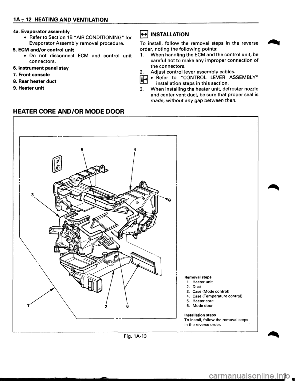
HEATER CORE AND/OR MODE DOOR
3
1
5
2 6
4
I••! INSTALLATION
To install, follow the removal steps in the reverse
order,
noting the following points:
1. When handling the ECM and the control unit, be
careful not to make any improper connection of
the connectors.
2. Adjust control lever assembly cables.
FEI • Refer to "CONTROL LEVER ASSEMBLY"
-installation steps in this section.
3. When installing the heater unit, defroster nozzle
and center vent duct, be sure that proper seal is
made,
without any gap between then.
Removal steps 1. Heater unit 2. Duct 3. Case (Mode control) 4. Case (Temperature control)
5. Heater core 6. Mode door
Installation steps To install, follow the removal steps
in the reverse order.
Fig. 1A-13
..
Page 49 of 1928
HEATING AND VENTILATION 1A-19
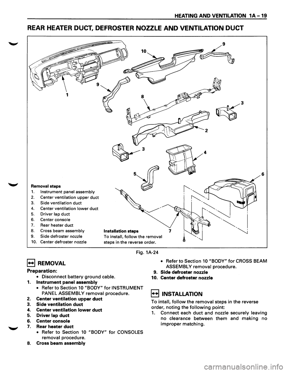
REAR HEATER DUCT, DEFROSTER NOZZLE AND VENTILATION DUCT
6
Removal steps
1. Instrument panel assembly
2. Center ventilation upper duct
3. Side ventilation duct
4. Center ventilation lower duct
5. Driver lap duct
6. Center console
7. Rear heater duct
8. Cross beam assembly Installation steps
9. Side defroster nozzle
10. Center defroster nozzle
To install, follow the removal
steps in the reverse order.
Fig. 1A-24
B REMOVAL
Preparation:
• Disconnect battery ground cable.
1. Instrument panel assembly
• Refer to Section 10 "BODY" for INSTRUMENT
PANEL ASSEMBLY removal procedure.
2. Center ventilation upper duct
3. Side ventilation duct
4. Center ventilation lower duct
5. Driver lap duct
6. Center console
7. Rear heater duct
• Refer to Section 10 "BODY" for CONSOLES
removal
procedure.
8. Cross beam assembly
• Refer to Section 10 "BODY" for CROSS BEAM
ASSEMBLY
removal procedure.
9. Side defroster nozzle
10. Center defroster nozzle
~!!) INSTALLATION
To intall, follow the removal steps in the reverse
order,
noting the following point:
1. Connect each duct and nozzle securely leaving
no clearance between them and making no
improper matching.
Page 50 of 1928
1A-20 HEATING AND VENTILATION
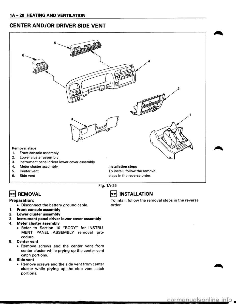
CENTER AND/OR DRIVER SIDE VENT
5
6
' -~
'
"
Removal steps
1. Front console assembly
2. Lower cluster assembly
3. Instrument panel driver lower cover assembly
4. Meter cluster assembly
5. Center vent
6. Side vent
4
Installation steps
To install, follow the removal
steps in the reverse order.
2
1
Fig. 1A-25
B REMOVAL
Preparation:
• Disconnect the battery ground cable.
1. Front console assembly
2. Lower cluster assembly
3. Instrument panel driver lower cover assembly
4. Meter cluster assembly
•
Refer to Section 10 "BODY" for INSTRU
MENT PANEL ASSEMBLY removal pro-
cedure.
5. Center vent
• Remove screws and the center vent from
center cluster while prying up the center vent
catch portions.
6. Side vent
• Remove screws and the side vent from center
cluster while prying up the side vent catch
portions.
E] INSTALLATION
To intall, follow the removal steps in the reverse
order.
..
Page 217 of 1928
SUPPLEMENTAL RESTRAINT SYSTEM (SRS) STEERING WHEEL & COLUMN 3F4-7
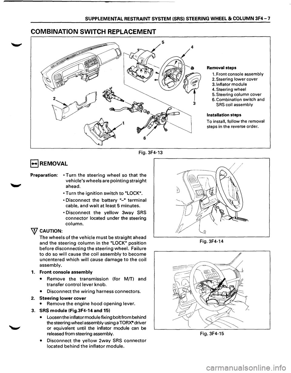
COMBINATION SWITCH REPLACEMENT
Fig. 3F4-13
E) REMOVAL
Preparation: • Turn the steering wheel so that the
vehicle's wheels are pointing straight
ahead.
W CAUTION: •
Turn the ignition switch to "LOCK".
•
Disconnect the battery "-" terminal
cable, and wait at least 5 minutes.
• Disconnect the yellow 3way SRS
connector located under the steering
column.
The wheels ofthe vehicle must be straight ahead
and
the steering column in the "LOCK" position
before disconnecting the steering wheel. Failure
to do so will cause the coil assembly to become
uncentered
which will cause damage to the coil
assembly.
1.
Front console assembly
•
Remove the transmission (for M{f) and
transfer control lever knob.
• Disconnect the wiring harness connectors.
2. Steering lower cover
• Remove the engine hood opening lever.
3. SRS module (Fig.3F4-14 and 15)
• Loosen the inflator module fixing bolt from behind
the steering
wheel assembly using a TORxe driver
or
equivalent until the inflator module can be
released from steering assembly.
•
Disconnect the yellow 2way SRS connector
located behind the inflator module.
3
Removal steps
1. Front console assembly
2. Steering lower cover
3.1nflator module
4. Steering wheel
5. Steering column cover
6. Combination switch and
SRS coil assembly
Installation steps
To install, follow the removal
steps in the reverse order.
Fig. 3F4-14
Fig. 3F4-15
Page 220 of 1928
3F4-10 SUPPLEMENTAL RESTRAINT SYSTEM (SRS) STEERING WHEEL & COLUMN
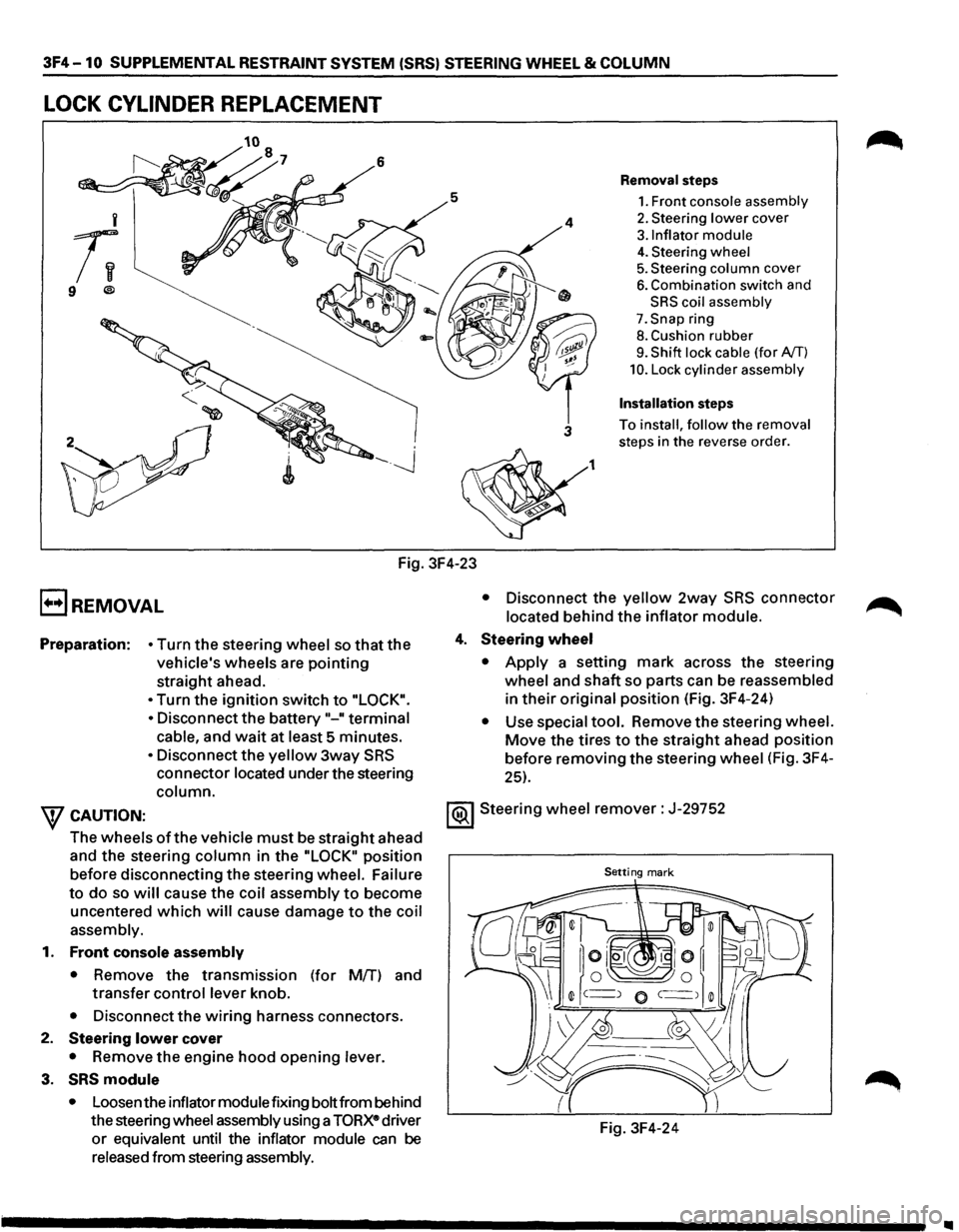
LOCK CYLINDER REPLACEMENT
5
i
;;
9 ®
Fig. 3F4-23
E) REMOVAL
4
3
1
Removal steps
1. Front console assembly
2. Steering lower cover
3.1nflator module
4. Steering wheel
5. Steering column cover
6. Combination switch and
SRS coil assembly
7. Snap ring
8. Cushion rubber
9. Shift lock cable (for AfT)
10. Lock cylinder assembly
Installation steps
To install, follow the removal
steps in the reverse order.
• Disconnect the yellow 2way SRS connector
located behind the inflator module.
Preparation:
• Turn the steering wheel so that the
vehicle's wheels are
pointing
straight ahead.
4. Steering wheel
• Turn the ignition switch to "LOCK".
•
Disconnect the battery"-" terminal
cable, and wait at least 5 minutes.
• Disconnect the yellow 3way SRS
connector located under the steering
column.
• Apply a setting mark across the steering
wheel and
shaft so parts can be reassembled
in
their original position (Fig. 3F4-24)
• Use special tool. Remove the steering wheel.
Move the tires to the straight ahead position
before removing the steering wheel (Fig. 3F4-
25).
W CAUTION: 1®.1 Steering wheel remover: J-29752
The wheels
of the vehicle must be straight ahead
and the steering
column in the "LOCK" position
before disconnecting the steering wheel. Failure
Setting mark
to do so will cause the coil assembly to become
uncentered
which will cause damage to the coil
assembly.
1.
Front console assembly
• Remove the transmission (for Mff) and
transfer
control lever knob.
• Disconnect the wiring harness connectors.
2. Steering lower cover
• Remove the engine hood opening lever.
3. SRS module
• Loosen the inflator module fixing bolt from behind
the steering wheel assembly using a
TORXe driver
or equivalent until the inflator module can be
released from steering assembly. Fig.
3F4-24
•
Page 224 of 1928
3F4-14 SUPPLEMENTAL RESTRAINT SYSTEM (SRS) STEERING WHEEL & COLUMN
EJREMOVAL
Preparation: • Turn the steering wheel so that the
vehicle's
wheels are pointing straight
ahead.
• Turn the ignition switch to "LOCK".
•
Disconnect the battery "-" terminal
cable,
and wait at least 5 minutes.
• Disconnect the yellow 3way SRS
connector located under the steering
column.
wcAUTION:
The wheel of the vehicle must be straight ahead
and the steering
column in the "LOCK• position
before disconnecting the steering
column from
the steering gear.
Failure to do so will cause the SRS coil assembly
to become uncentered which will cause damage
to the SRS coil assembly.
1. Front console assembly
• Disconnect the transmission (for MfT) and
transfer
control lever knob.
• Disconnect the wiring harness connectors.
2. Steering lower cover
• Remove the engine hood opening lever.
3. Driver knee bolster (reinforcement)
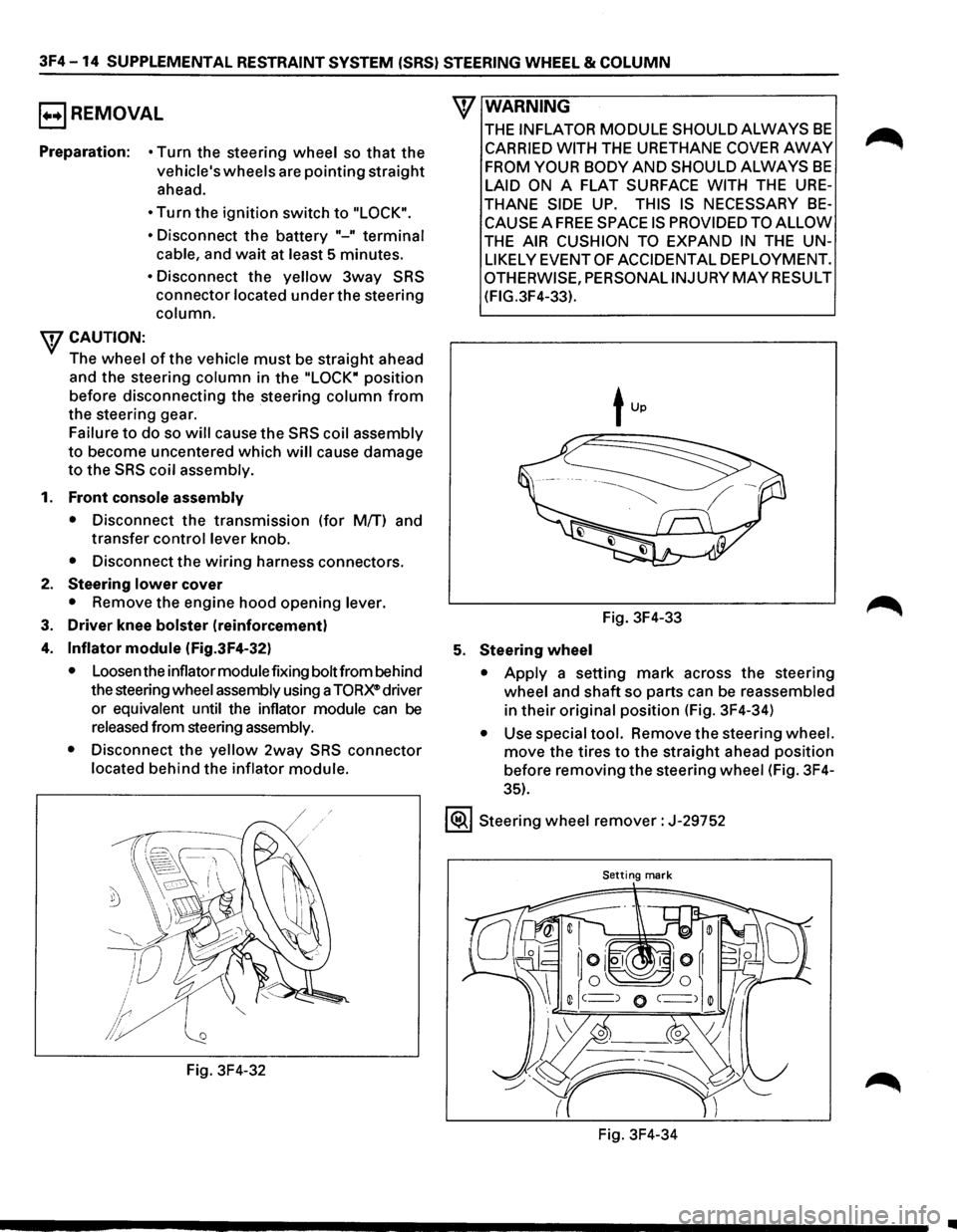
4. Inflator module (Fig.3F4-32)
• Loosen the inflator module fixing bolt from behind
the steering
wheel assembly using a TORX® driver
or
equivalent until the inflator module can be
released from steering assembly.
•
Disconnect the yellow 2way SRS connector
located behind the inflator module.
Fig. 3F4-32
\V WARNING
THE INFLATOR MODULE SHOULD ALWAYS BE
CARRIED WITH THE URETHANE COVER AWAY
FROM YOUR BODY AND SHOULD ALWAYS BE
LAID ON A FLAT SURFACE WITH THE URE
THANE SIDE UP. THIS IS NECESSARY BE
CAUSE A FREE SPACE IS PROVIDED TO ALLOW
THE AIR CUSHION TO EXPAND IN THE UN
LIKELY EVENT OF ACCIDENTAL DEPLOYMENT.
OTHERWISE, PERSONALINJURYMAYRESULT
(FIG.3F4-33).
Fig. 3F4-33
5. Steering wheel
• Apply a setting mark across the steering
wheel and shaft so parts can be reassembled
in their original position (Fig. 3F4-34)
• Use special tool. Remove the steering wheel.
move the tires to the straight ahead position
before removing the steering
wheel (Fig. 3F4-
35).
1®.1 Steering wheel remover: J-29752
Setting mark
Fig. 3F4-34
..
Page 369 of 1928
REAR WHEEL ANTILOCK BRAKE SYSTEM 5A3-1
SECTION 5A3
REAR WHEEL ANTILOCK BRAKE SYSTEM
(RWAL}
w CAUTION:
• All brake attaching fasteners are an important attaching part in that they could affect performance of vital
parts and systems, and/or could result in major repair expense. They must be replaced with one of the same
part
number or with an equivalent part if replacement becomes necessary. Do not use replacement parts of
lesser quality or substitute design. Torque values must be used as specified during reassembly to assure
proper retention of these parts.
CONTENTS
Introduction . . . . . . . . . . . . . . . . . . . . . . . . . 5A3· 1
General Description . .
. . . . . . . . . . . . . . .
5A3· 1
Rear
Wheel Antilock (RWAL) Control
Parts Location . .
. . . . . . . . . . . . . . . . .
5A3· 5
System Diagram . .
. . . . . . . . . . . . . . . . . . . .
5A3· 6
Rear
Wheel Antilock (RWAL) System
Diagnostics . .
. . . . . . . . . . . . . . . . . . . . . .
5A3· 7
On-Vehicle Service . .
. . . . . . . . . . . . . . . . .
5A3·38
RWAL Electronic Brake Control
Module (EBCM) Replacement ....... 5A3-38
Antilock
(Isolation/Dump) Valve
Replacement ..................... 5A3-39
Speed Sensor Replacement
.......... 5A3-40
Main Data and Specifications ........... 5A3-41
Torque Specifications
............... 5A3-41
INTRODUCTION
This section deals with the complete diagnosis and
services
for vehicles equipped with rear wheel
antilock.
For service information regarding all other
components
of the brake system, refer to "Hydraulic
Brakes"
(Sec. SA), "Brake Booster System" (Sec. SA 1)
or "Disc Brakes" (Sec. SA2) of this Manual.
GENERAL DESCRIPTION
The rear wheel anti lock system (RWAL) is designed to
reduce rear wheel lock-up during a severe brake
application,
thus maintaining rear end stability. The
system functions
by regulating the rear hydraulic
brake line pressure. The pressure regulation is
accomplished
by an anti lock valve which is located on
the
front right side of engine room. The anti lock valve
is made up of two valves, a dump valve which releases
pressure into an accumulator and an isolation valve
which maintains rear brake pressure. The valve is
controlled
by a microcomputer which is part of the
Electronic Brake Control Module (EBCM). The
EBCM is mounted at the
front of the center
console. Under severe brake application, as pressure
is
applied to the brake pedal, the EBCM is designed to
permit the valve to do one of three functions or a
combination
of all three. The EBCM will allow the valve
to either maintain the same amount of hydraulic
pressure, release hydraulic pressure through the
dump valve into the accumulator or increase the
pressure by
pulsing the isolation valve.
The EBCM operates by receiving signals from the
speed sensor (which
is located in the differential
carrier), combination
valve and the brake light switch.
The RWAL system is connected
to the RWAL indicator
light located on the dash. An indication of the RWAL
operation and a
bulb check is performed each time the
ignition is turned
"ON". The indicator light will remain
on
for about two seconds. A RWAL system
malfunction is indicated if the RWAL indicator light
stays on, or comes on during driving. To determine the
specific
trouble, refer to "RWAL System Diagnostics"
in this section.
Page 371 of 1928
REAR WHEEL ANTILOCK BRAKE SYSTEM 5A3-3
ELECTRONIC BRAKE CONTROL MODULE
(EBCM)
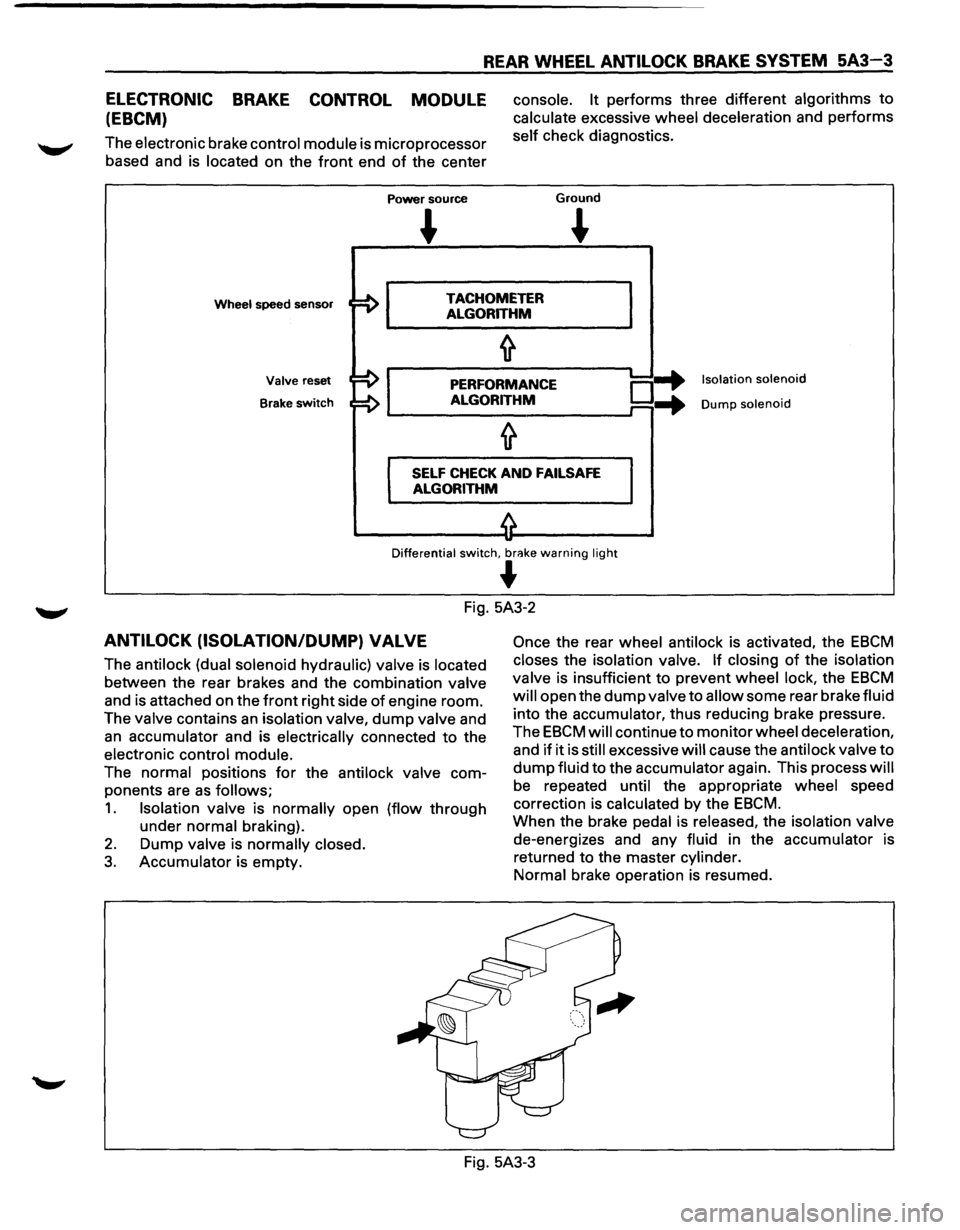
The electronic brake control module is microprocessor
based and is located on the
front end of the center
Power source
console. It performs three different algorithms to
calculate excessive wheel deceleration and performs
self check diagnostics.
Ground
~
Wheel speed sensor TACHOMETER
ALGORITHM
Valve reset
Brake
switch
PERFORMANCE
ALGORITHM o-+ ...
Isolation solenoid
Dump solenoid
SELF CHECK AND FAILSAFE
ALGORITHM
Differential switch, br<'!ke warning light
~
Fig. 5A3-2
ANTILOCK (ISOLATION/DUMP) VALVE
The antilock (dual solenoid hydraulic) valve is located
between the rear brakes and the combination valve
and is attached on the
front right side of engine room.
The valve contains
an isolation valve, dump valve and
an accumulator and is electrically connected to the
electronic control module.
The normal positions
for the antilock valve com
ponents are
as follows;
1. Isolation valve is normally open (flow through
under normal braking).
2. Dump valve is normally closed.
3. Accumulator is empty.
Once the rear wheel antilock is activated, the EBCM
closes the isolation valve. If closing of the isolation
valve is insufficient to prevent wheel lock, the
EBCM
will open the dump valve to allow some rear brake fluid
into the accumulator, thus reducing brake pressure.
The
EBCM will continue to monitor wheel deceleration,
and
if it is still excessive will cause the antilock valve to
dump fluid to the accumulator again. This process will
be repeated until the appropriate wheel speed
correction is calculated by the
EBCM.
When the brake pedal is released, the isolation valve
de-energizes and any fluid in the accumulator is
returned to the master cylinder.
Normal brake operation is resumed.
Fig. 5A3-3
Page 373 of 1928
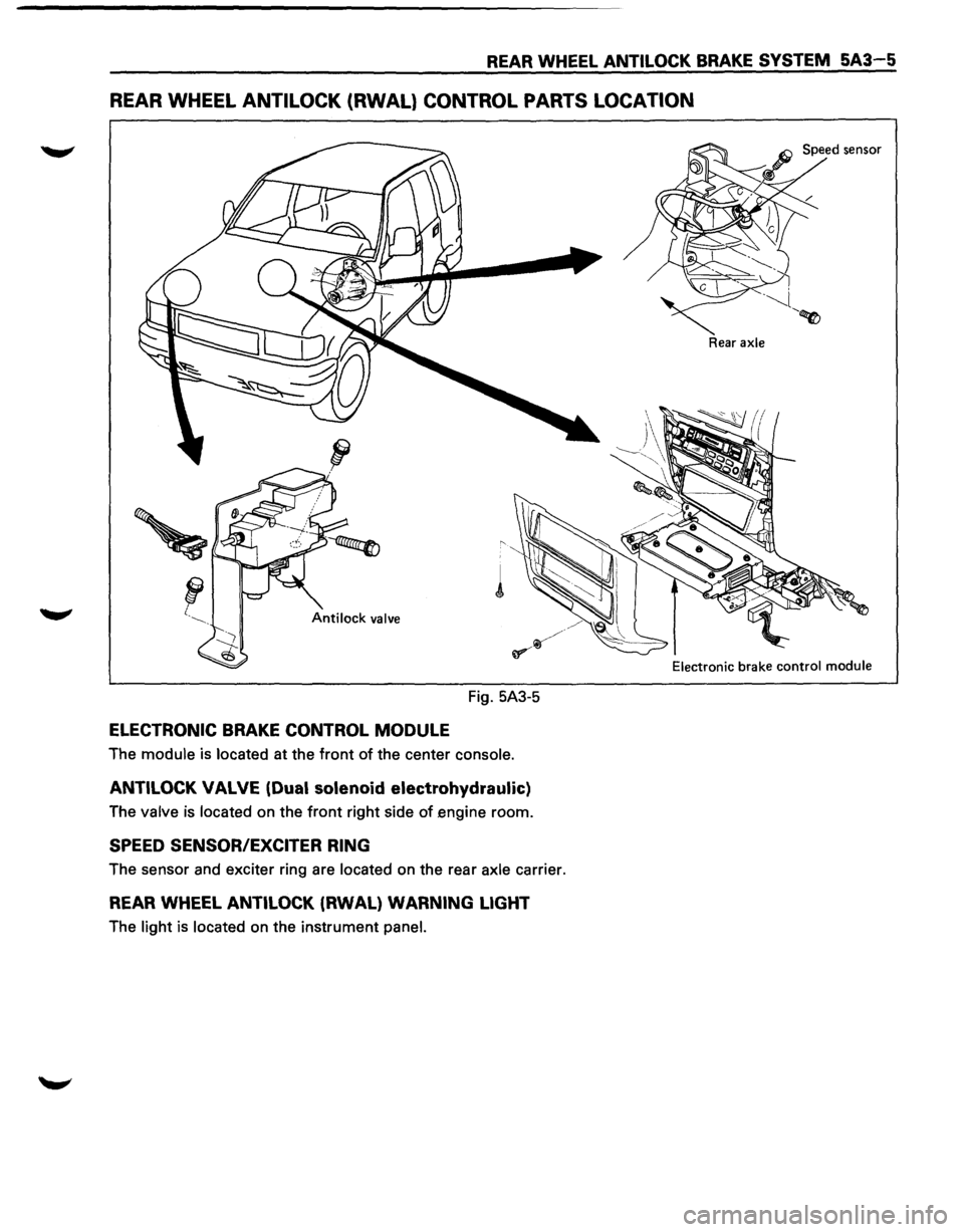
REAR WHEEL ANTILOCK BRAKE SYSTEM 5A3-5
REAR WHEEL ANTILOCK (RWAL} CONTROL PARTS LOCATION
Fig. 5A3-5
ELECTRONIC BRAKE CONTROL MODULE
The module is located at the front of the center console.
ANTILOCK VALVE (Dual solenoid electrohydraulic)
The valve is located on the front right side of engine room.
SPEED SENSOR/EXCITER RING
The sensor and exciter ring are located on the rear axle carrier.
REAR WHEEL ANTILOCK (RWAL) WARNING LIGHT
The light is located on the instrument panel.
Rear axle
Electronic
brake control module
Page 414 of 1928
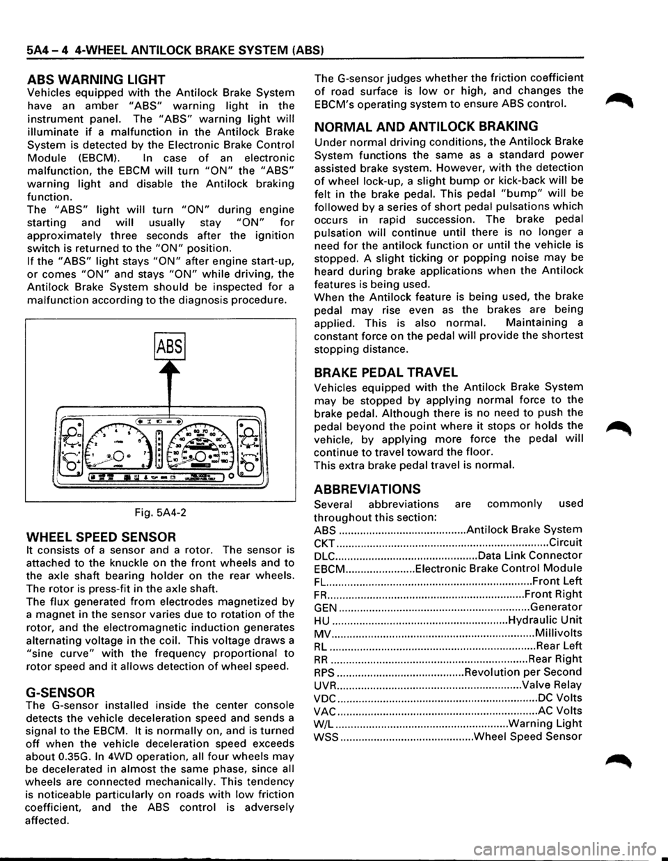
5A4-4 4-WHEEL ANTILOCK BRAKE SYSTEM (ABS)
ABS WARNING LIGHT
Vehicles equipped with the Antilock Brake System
have an
amber "ABS" warning light in the
instrument panel. The "ABS" warning light will
illuminate if a malfunction in the Antilock Brake
System is detected by the Electronic Brake
Control
Module (EBCM). In case of an electronic
malfunction, the EBCM will turn "ON" the "ABS"
warning light and disable the Antilock braking
function.
The
"ABS" light will turn "ON" during engine
starting and
will usually stay "ON" for
approximately three seconds after the ignition
switch is returned to the "ON" position.
If the "ABS" light stays "ON" after engine start-up,
or comes "ON" and stays "ON" while driving, the
Antilock Brake System should be inspected
for a
malfunction according to the diagnosis procedure.
Fig. 5A4-2
WHEEL SPEED SENSOR
It consists of a sensor and a rotor. The sensor is
attached
to the knuckle on the front wheels and to
the axle shaft bearing holder on the rear wheels.
The
rotor is press-fit in the axle shaft.
The
flux generated from electrodes magnetized by
a magnet in the sensor varies due to rotation of the
rotor, and the electromagnetic
induction generates
alternating voltage in
the coil. This voltage draws a
"sine curve" with the frequency proportional to
rotor speed and it allows detection of wheel speed.
G-SENSOR
The G-sensor installed inside the center console
detects the vehicle deceleration speed and sends a
signal
to the EBCM. It is normally on, and is turned
off when the vehicle deceleration speed exceeds
about 0.35G.
In 4WD operation, all four wheels may
be decelerated in almost the same phase, since all
wheels are connected mechanically. This tendency
is noticeable particularly on roads
with low friction
coefficient, and the
ABS control is adversely
affected. The
G-sensor judges
whether the friction coefficient
of road surface is low or high, and changes the
EBCM's operating system to ensure ABS control.
NORMAL AND ANTILOCK BRAKING
Under normal driving conditions, the Antilock Brake
System functions the same
as a standard power
assisted brake system. However, with the detection
of wheel lock-up, a slight bump or kick-back will be
felt in the brake pedal. This pedal
"bump" will be
followed by a series of short pedal pulsations which
occurs in rapid succession. The brake pedal
pulsation
will continue until there is no longer a
need
for the antilock function or until the vehicle is
stopped. A
slight ticking or popping noise may be
heard
during brake applications when the Antilock
features is being used.
When the
Antilock feature is being used, the brake
pedal
may rise even as the brakes are being
applied. This is also
normal. Maintaining a
constant force on the pedal
will provide the shortest
stopping distance.
BRAKE PEDAL TRAVEL
Vehicles equipped with the Antilock Brake System
may be stopped by applying normal force to the
brake pedal.
Although there is no need to push the
pedal beyond the
point where it stops or holds the ~
vehicle, by applying more force the pedal will
continue to travel toward the floor.
This extra brake pedal travel is normal.
ABBREVIATIONS
Several abbreviations are commonly used
throughout this section:
ABS .......................................... Antilock Brake System
CKT ...................................................................... Circuit
DLC ............................................... Data Link Connector
EBCM ....................... Eiectronic Brake Control Module
FL. ................................................................... Front Left
FR ................................................................. Front Right
GEN ............................................................... Generator
HU .......................................................... Hydraulic Unit
MV ................................................................... Millivolts
RL .................................................................... Rear Left
RR ................................................................. Rear Right
RPS .......................................... Revolution per Second
UVR ............................................................. Valve Relay
VDC .................................................................. DC Volts
VAC .................................................................. AC Volts
W/L .........................................................
Warning Light
WSS ............................................ Wheel Speed Sensor