center console ISUZU TROOPER 1995 User Guide
[x] Cancel search | Manufacturer: ISUZU, Model Year: 1995, Model line: TROOPER, Model: ISUZU TROOPER 1995Pages: 1928
Page 485 of 1928
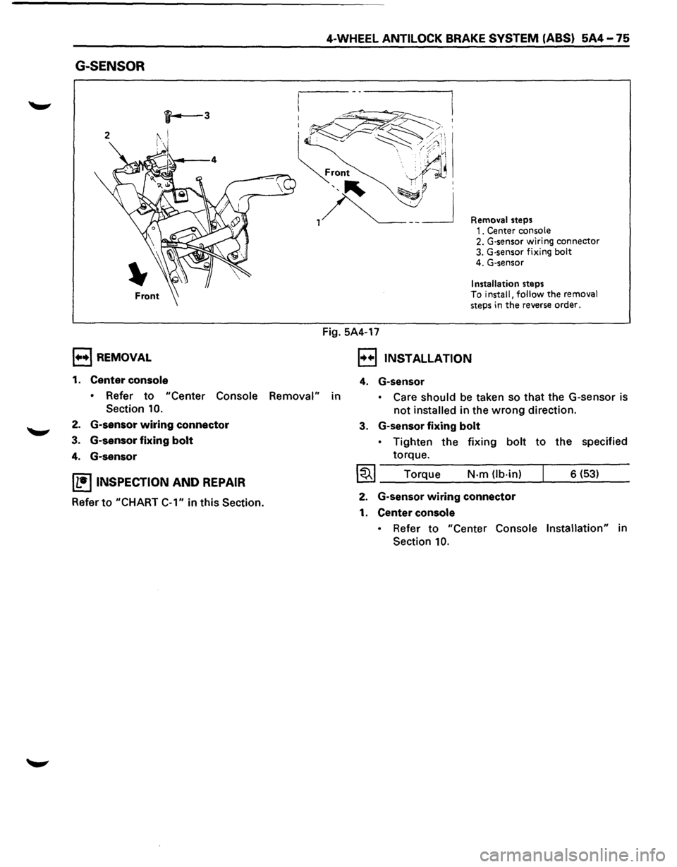
G-SENSOR
, .... ,REMOVAL
1. Center console
4-WHEEL ANTILOCK BRAKE SYSTEM (ABS) 5A4-75
Fig. 5A4-17
Removal steps 1. Center console 2. G-sensor wiring connector 3. G·sensor fixing bolt 4. G-sensor
Installation steps To install, follow the removal steps in the reverse order.
, .. .,, INSTALLATION
4. G-sensor
• Refer to "Center Console Removal" in • Care should be taken so that the G-sensor is
not installed in the wrong direction.
Section 10.
2. G-sensor wiring connector
3. G-sensor fixing bolt
4. G-sensor
IL•ItNSPECTION AND REPAIR
Refer to "CHART
C-1" in this Section.
3. G-sensor fixing bolt
• Tighten the fixing bolt to the specified
torque.
I~I ____ T_o_rq~u~e ____ N~·-m~(lb_·_in~)--~ ___ 6_(_53~) __ __
2. G-sensor wiring connector
1. Center console
• Refer to "Center Console Installation" in
Section
10.
Page 493 of 1928
~
PARKING BRAKES SC-3
ON-VEHICLE SERVICE
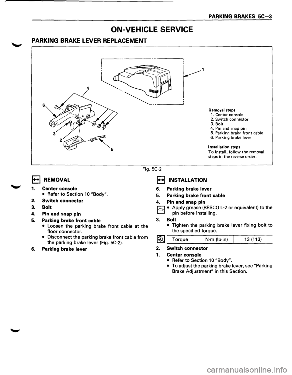
PARKING BRAKE LEVER REPLACEMENT
1
4
6
Removal steps
1. Center console
2. Switch
connector 3. Bolt
4. Pin and snap pin
5. Parking brake
front cable 6. Parking brake lever
Installation
steps
To install, follow the removal
steps in the reverse order.
Fig. 5C-2
l••l REMOVAL
1.
2.
3.
4.
5.
Center console
• Refer to Section 1 0 "Body".
Switch connector
Bolt
Pin and snap pin
Parking brake front
cable
• Loosen the parking brake front cable at the
floor connector.
• Disconnect the parking brake front cable from
the parking brake lever (Fig. 5C-2).
6. Parking brake lever
1••1 INSTALLATION
6. Parking brake lever
5. Parking brake front cable
4. Pin and snap pin
r:::J • Apply grease (BESCO L-2 or equivalent) to the
D pin before installing.
3. Bolt
• Tighten the parking brake lever fixing bolt to
the specified torque.
~~~ Torque N·m (lb·in) 13 (113)
2. Switch connector
1. Center console
• Refer to Section 10 "Body".
•
To adjust the parking brake lever, see "Parking
Brake Adjustment" in this Section.
Page 494 of 1928
5C-4 PARKING BRAKES
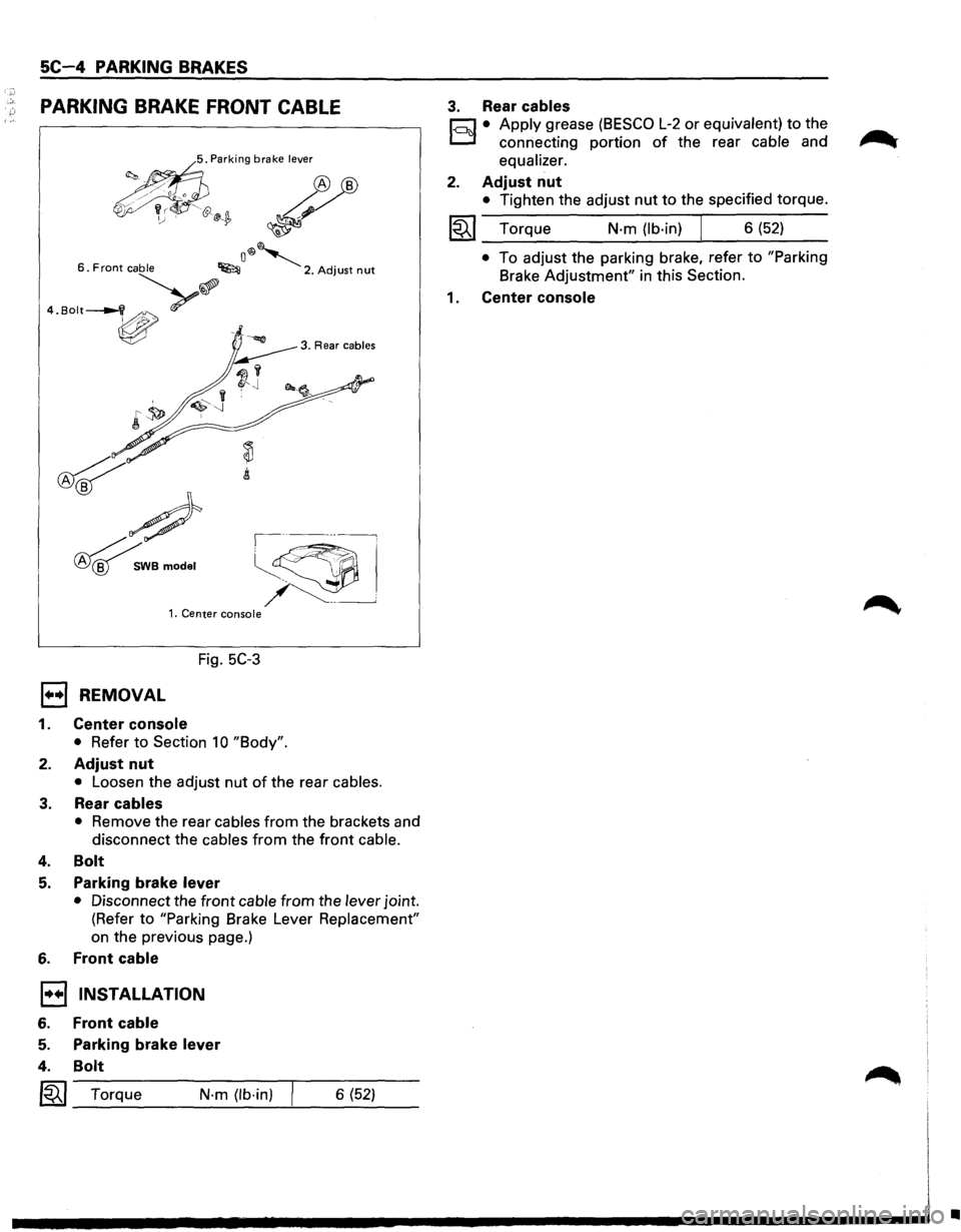
PARKING BRAKE FRONT CABLE
<.~ '"''"' brnke '""" ~
~~~ ~ ~
o®~ 6. Front cable ~ 2. Adjust nut
··"""-v>.?
~
~
#
~WBmodel
,----~
~~
~ ~--___j 1. Center console
Fig. 5C-3
1••1 REMOVAL
1. Center console
• Refer to Section 10 "Body".
2. Adjust nut
• Loosen the adjust nut of the rear cables.
3. Rear cables
• Remove the rear cables from the brackets and
disconnect the cables
from the front cable.
4. Bolt
5. Parking brake lever
• Disconnect the front cable from the lever joint.
(Refer to
"Parking Brake Lever Replacement"
on the previous page.)
6. Front cable
1•+1 INSTALLATION
6. Front cable
5.
4.
Parking brake lever
Bolt
I~I_T_o_rq_u_e ___ N_·_m_(lb_·_in_) --'---6_(_5_2) __
3. Rear cables
r;:::;:] • Apply grease (BESCO L-2 or equivalent) to the
D connecting portion of the rear cable and
equalizer.
2. Adjust nut
• Tighten the adjust nut to the specified torque.
~~~ Torque N-m (lb-in) J 6 (52)
• To adjust the parking brake, refer to "Parking
Brake
Adjustment" in this Section.
1 . Center console
•
Page 632 of 1928
68 - 4 ENGINE COOLING
ON-VEHICLE SERVICE
DRAINING AND REFILLING COOLING
SYSTEM
Before draining the cooling system, inspect the sys
tem and perform any necessary service to ensure that
it is clean, does not leak and is in proper working
order. The Engine Coolant (EC) level should be be
tween the "MIN" and "MAX" lines of reserve tank
when the engine is cold. If low, check for leakage and
add
EC up to the "MAX" line. There should not be any
excessive deposit of rust or scales around the radiator
cap
or radiator filler hole, and the EC should also be
free
from oil. Replace the EC if excessively dirty.
1. Completely drain the cooling system by opening
the drain petcock at the bottom of the radiator.
2. Remove the radiator cap.
W WARNING
To avoid the danger of being burned, do not
remove the cap while the engine and radiator
are still hot. Scalding fluid and steam can be
blown out under pressure.
3. Disconnect all hoses from the EC reserve tank.
Scrub and clean the inside of the reserve tank with
soap and water. Flush it well with clean water,
then drain it. Install the reserve tank and hoses.
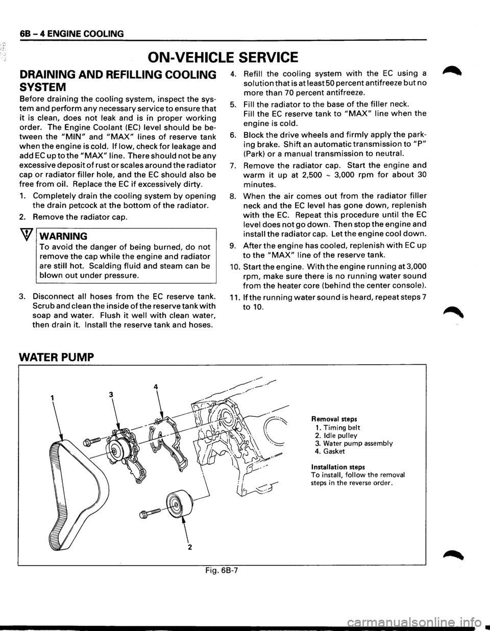
WATER PUMP
3
j
2
4. Refill the cooling system with the EC using a
solution that is at least 50 percent antifreeze but no
more than 70 percent antifreeze.
5. Fill the radiator to the base of the filler neck.
Fill the EC reserve tank to "MAX" line when the
engine is cold.
6. Block the drive wheels and firmly apply the park
ing brake.
Shift an automatic transmission to "P"
(Park) or a manual transmission to neutral.
7. Remove the radiator cap. Start the engine and
warm it up at 2,500 -3,000 rpm for about 30
minutes.
8. When the air comes out from the radiator filler
neck and the EC level has gone down, replenish
with the EC. Repeat this procedure until the EC
level does not go down. Then stop the engine and
install the radiator cap. Let the engine cool down.
9. After the engine has cooled, replenish with EC up
to the "MAX" line of the reserve tank.
10. Start the engine. With the engine running at 3,000
rpm, make sure there is no running water sound
from the heater core (behind the center console).
11. If the running water sound is heard, repeat steps 7
to 10.
Removal steps
1. Timing
belt 2. Idle pulley 3. Water pump assembly
4. Gasket
Installation steps To install, follow the removal steps in the reverse order.
Fig. 6B-7
•
Page 720 of 1928
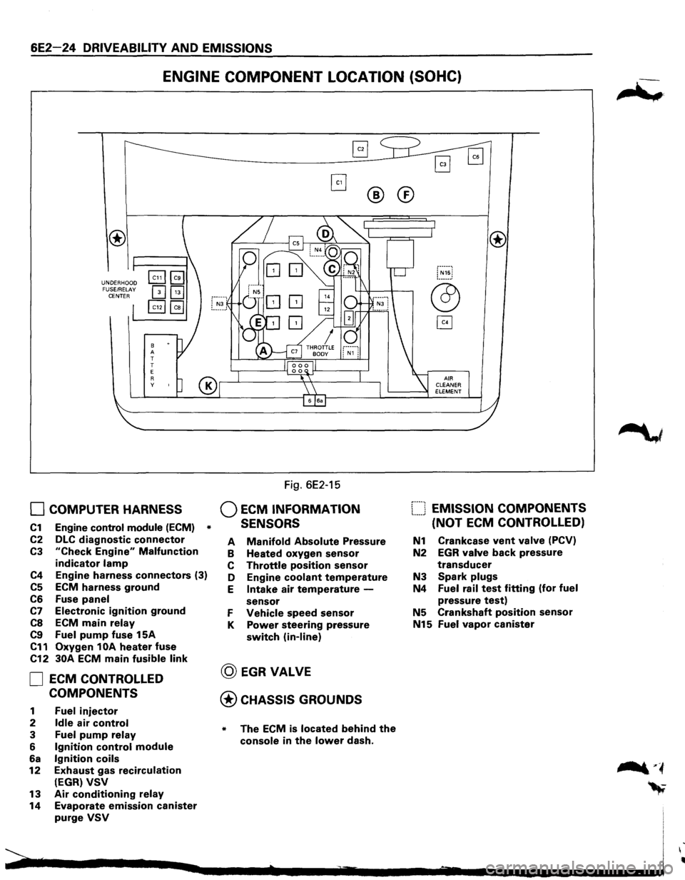
6E2-24 DRIVEABILITY AND EMISSIONS
ENGINE COMPONENT LOCATION (SOHC)
UNDERHOOD
FUSE/RELAY
CENTER
8 A
T
T
E
R y
0 COMPUTER HARNESS
C1 Engine control module (ECM) *
C2 DLC diagnostic connector
C3 "Check Engine" Malfunction
indicator lamp
C4 Engine harness connectors (3)
C5 ECM harness ground
C6 Fuse panel
C7 Electronic ignition ground
CS ECM main relay
C9 Fuel pump fuse 15A
C11 Oxygen 1 OA heater fuse
C12 30A ECM main fusible link
0 ECM CONTROLLED
COMPONENTS
1 Fuel injector
2 Idle air control
3 Fuel pump relay
6 Ignition control module
6a Ignition coils
12 Exhaust gas recirculation
(EGR) VSV
13 Air conditioning relay
14 Evaporate emission canister
purge VSV
Fig. 6E2-15
Q ECM INFORMATION
SENSORS
®
A Manifold Absolute Pressure
B Heated oxygen sensor
C Throttle position sensor
D Engine
coolant temperature
E Intake air temperature -
sensor
F Vehicle speed sensor
K Power steering pressure
switch (in-line)
@ EGRVALVE
@CHASSIS GROUNDS
* The ECM is located behind the
console in the lower dash.
®
[::::J EMISSION COMPONENTS
(NOT
ECM CONTROLLED)
N1 Crankcase vent valve (PCV)
N2 EGR valve back pressure
transducer
N3 Spark plugs
N4 Fuel rail test fitting (for fuel
pressure test)
N5 Crankshaft position sensor
N15 Fuel vapor canister
Page 721 of 1928
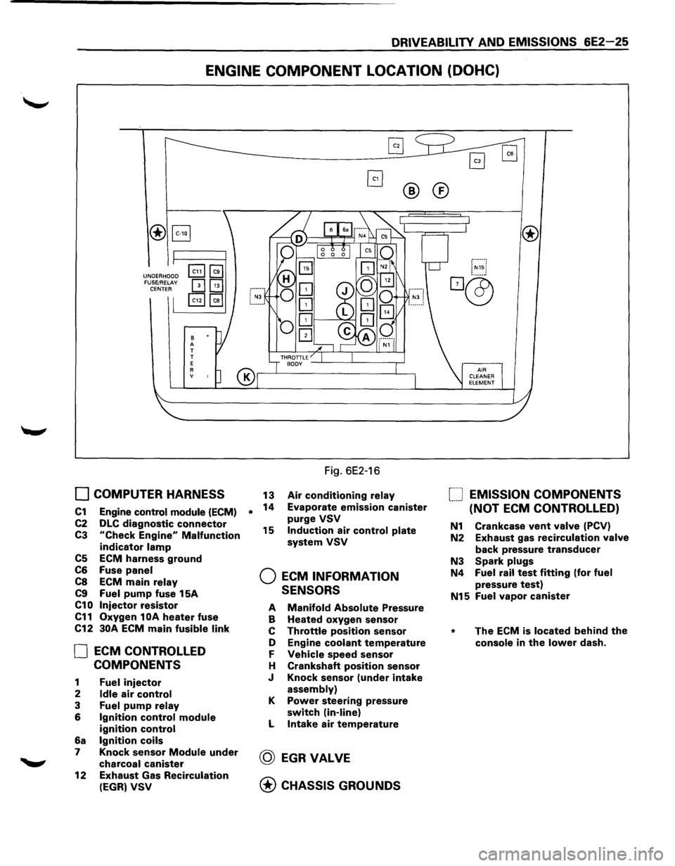
DRIVEABILITY AND EMISSIONS 6E2-25
ENGINE COMPONENT LOCATION (DOHC)
®B
UNDERHOOD FUSE/RELAY CENTER
B A T
T
E
A y
0 COMPUTER HARNESS
C1 Engine control module (ECM)
C2 DLC diagnostic connector
C3 "Check Engine" Malfunction
indicator lamp
C5 ECM harness ground
C6 Fuse panel
C8 ECM main relay
C9 Fuel pump fuse 15A
C10 Injector resistor
C11 Oxygen 1 OA heater fuse
C12
30A ECM main fusible link
0 ECM CONTROLLED
COMPONENTS
1 Fuel injector
2 Idle air control
3 Fuel pump relay
6 Ignition control module
ignition control
6a Ignition coils
7 Knock sensor Module under
charcoal canister
12
Exhaust Gas Recirculation
(EGR) VSV
*
®®
Fig. 6E2-16
13 Air conditioning relay
14 Evaporate emission canister
purge VSV
15 Induction air control plate
system VSV
Q ECM INFORMATION
SENSORS
A Manifold Absolute Pressure
B Heated oxygen sensor
c Throttle position sensor
D Engine
coolant temperature
F Vehicle speed sensor
H Crankshaft
position sensor
J Knock sensor
(under intake
assembly)
K Power steering pressure
switch (in-line)
L Intake air temperature
@ EGRVALVE
@ CHASSIS GROUNDS
f----1 EMISSION COMPONENTS !.-----' (NOT ECM CONTROLLED)
N1 Crankcase vent valve (PCV)
N2 Exhaust gas
recirculation valve
back pressure transducer
N3 Spark plugs
N4 Fuel rail test fitting (for fuel
pressure test)
N15 Fuel vapor canister
* The ECM is located behind the
console in the lower dash.
Page 1033 of 1928
1••1 REMOVAL
Preparation:
• Remove engine hood.
• Disconnect negative (-) battery cable.
1. Skid plate
2. Exhaust and transfer protectors
3. Rear propeller shaft
4. Front propeller shaft
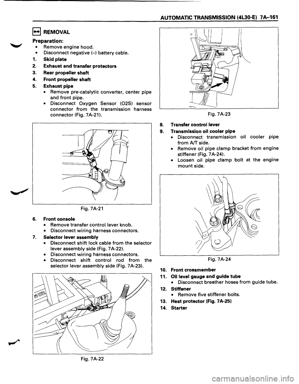
5. Exhaust pipe
• Remove pre-catalytic converter, center pipe
and
front pipe.
• Disconnect Oxygen Sensor (025) sensor
connector
from the transmission harness
connector (Fig.
7A-21).
Fig. 7A-21
6. Front console
• Remove transfer control lever knob.
• Disconnect wiring harness connectors.
7. Selector lever assembly
• Disconnect shift lock cable from the selector
lever assembly
side (Fig. 7 A-22).
• Disconnect wiring harness connectors.
• Disconnect shift control rod from the
selector lever assembly side (Fig. 7 A-23).
Fig. 7A-22
AUTOMATIC TRANSMISSION (4L30·E) 7A-161
Fig. 7A-23
8. Transfer control lever
9. Transmission oil cooler
pipe
• Disconnect transmission oil cooler pipe
from AfT side.
• Remove oil pipe clamp bracket from engine
stiffener (Fig.
7 A-24).
• Loosen oil pipe clamp bolt at the engine
mount side.
Fig.
7A-24
10. Front crossmember
11.
Oil level gauge and guide tube
• Disconnect breather hoses from guide tube.
12.
Stiffener
• Remove five stiffener bolts.
13. Heat protector (Fig. 7A-25}
14.
Starter
Page 1099 of 1928
12. Flywheel under cover bolts
• Install
three flywheel under cover bolts.
11. Gear control lever
• Install
the transmission control lever and
transfer
control lever.
• Install
the grommet assembly.
• Install
the front console assembly.
• Install
the gear control lever knob.
• Support the transfer case with a jack and then
remove the transmission jack
from
transmission side.
10. Front propeller shaft
• Install the front propeller shaft.
~~~ Torque N·m (lb·ft) 63 (46)
9. Front crossmember
• Install the front crossmember.
~~~ Torque N·m (lb·ft) 78 (58)
8. Engine rear mount
• Install the engine rear mount.
~~~ Torque N·m (lb·ft) 41 (30)
7. 3rd crossmember
• Install the 3rd crossmember.
1~1 Torque N-m (lb·ft) 50 (37)
6. Engine rear mount nuts
~~~ Torque N-m (lb·ft) 50 (37)
• Remove the transmission jack.
5. Transmission harness connectors
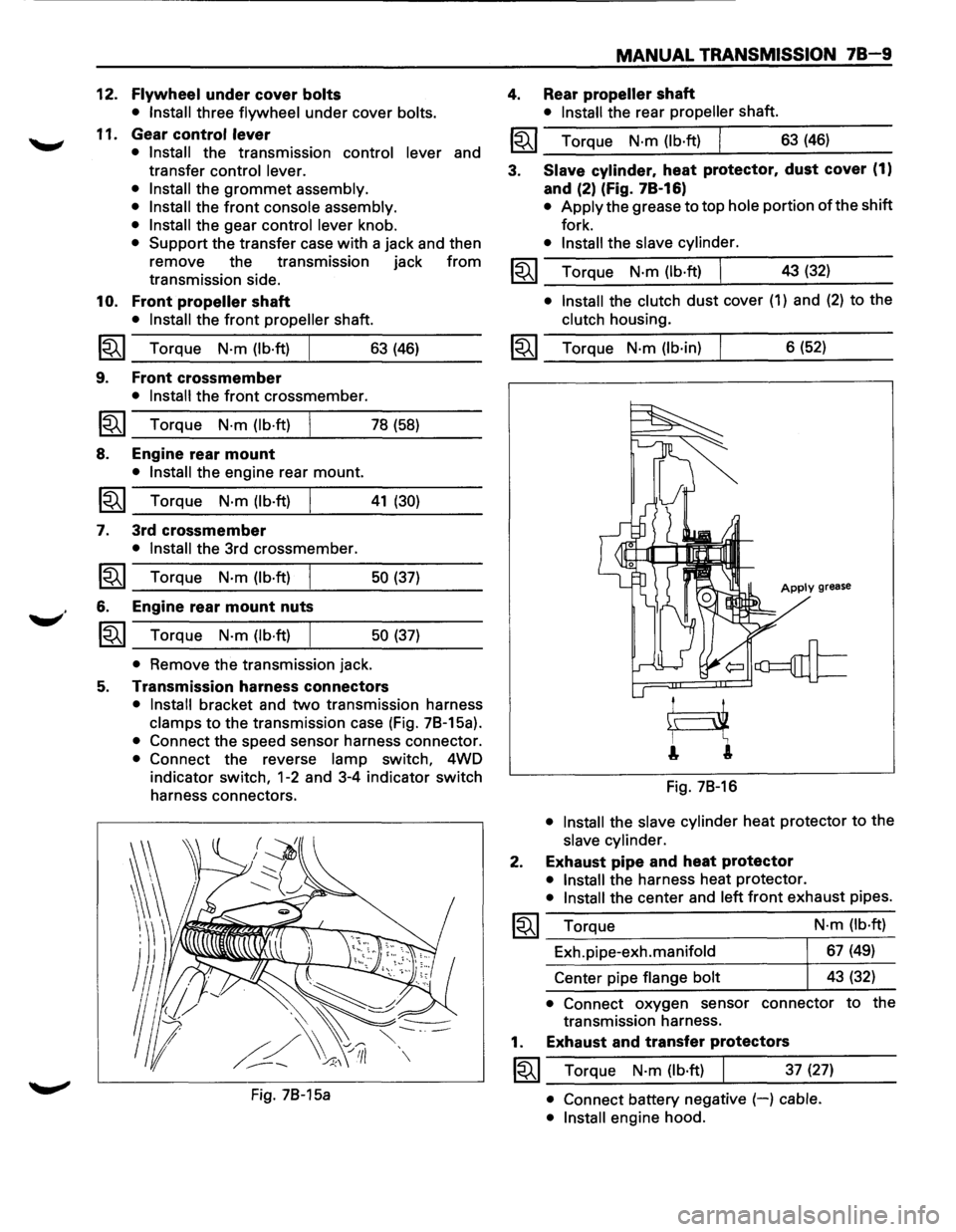
• Install bracket and two transmission harness
clamps to the transmission case (Fig. 78-15a).
• Connect the speed sensor harness connector.
• Connect the reverse lamp switch, 4WD
indicator
switch, 1-2 and 3-4 indicator switch
harness connectors.
Fig. 78-15a
MANUAL TRANSMISSION 78-9
4. Rear propeller shaft
• Install the rear propeller shaft.
I~I __ T_o_rq~u_e __ N_·m~(_lb_·ft~)~ _____ 6_3~(_46~) ____ _
3. Slave cylinder. heat protector. dust cover (1)
and (2) (Fig. 78-16)
• Apply the grease to top hole portion of the shift
fork.
• Install the slave cylinder.
~~~ Torque N·m (lb·ft) I 43 (32) _..:....__~----
• Install the clutch dust cover (1) and (2) to the
clutch housing.
~~~ Torque N·m (lb·in) 6 (52)
Apply grease
Fig. 78-16
• Install the slave cylinder heat protector to the
slave cylinder.
2. Exhaust pipe and heat protector
• Install the harness heat protector.
• Install the center and left front exhaust pipes.
~~~ Torque
Exh.pipe-exh.manifold
Center pipe
flange bolt N·m
(lb·ft)
67 (49)
43 (32)
• Connect oxygen sensor connector to the
transmission harness.
1. Exhaust and transfer protectors
~~~ Torque N·m (lb·ft) 37 (27)
• Connect battery negative (-) cable.
• Install
engine hood.
Page 1161 of 1928
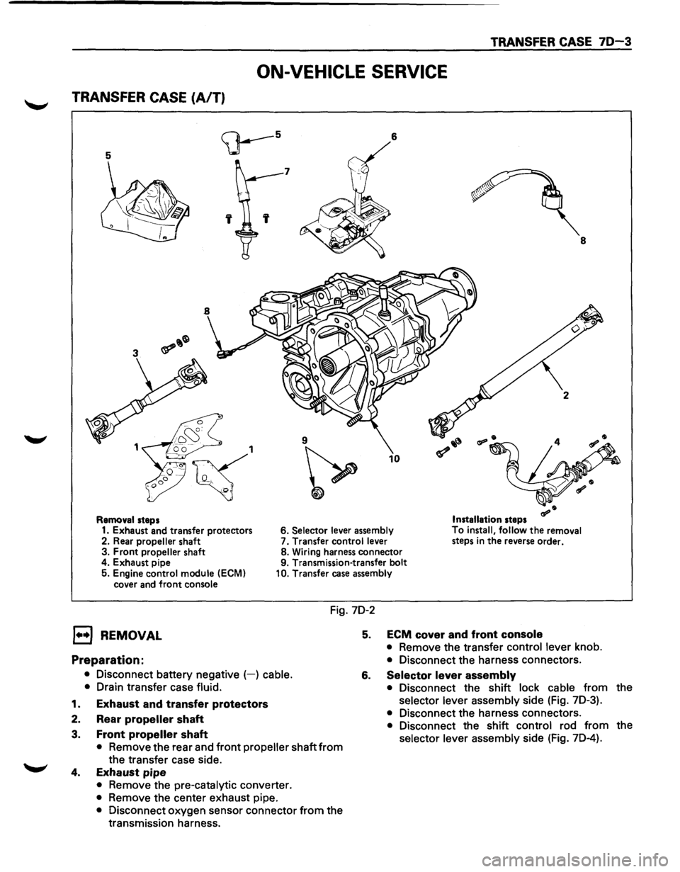
TRANSFER CASE 70-3
ON-VEHICLE SERVICE
TRANSFER CASE (A/T)
5
<;J---5 6
7
' 8
9
~
10
Removal steps Installation steps
1. Exhaust and transfer protectors 6. Selector lever
assembly To
install, follow the removal
steps in the reverse order.
2. Rear propeller shaft 7.
Transfer control lever
3. Front propeller shaft 8.
Wiring harness connector
4. Exhaust pipe 9. Transmission-transfer bolt
5. Engine control module
(ECM)
cover and front console 10.
Transfer case assembly
Fig. 7D-2
l••l REMOVAL
Preparation:
• Disconnect battery negative (-) cable.
•
Drain transfer case fluid.
1. Exhaust and transfer protectors
2. Rear propeller shaft
3. Front propeller shaft
• Remove the rear and front propeller shaft from
the transfer case side.
4. Exhaust pipe
• Remove the pre-catalytic converter.
• Remove the center exhaust pipe.
• Disconnect oxygen sensor connector from the
transmission harness.
5. ECM cover and front console
• Remove the transfer control lever knob.
• Disconnect the harness connectors.
6. Selector lever assembly
• Disconnect the shift lock cable from the
selector lever assembly side (Fig. 7D-3).
• Disconnect the harness connectors.
• Disconnect the shift control rod from the
selector lever assembly side (Fig. 7D-4).
Page 1368 of 1928
8 -178 CHASSIS ELECTRICAL
ANTI-LOCK BRAKE SYSTEM (ABS)
GENERAL DESCRIPTION
The circuit consists of the starter switch, stoplight switch (vehicle w/o cruise control), brake switch (vehicle
with cruise control), hydraulic unit, electronic brake control module, wheel speed sensor, G sensor, ABS and
4WD indicator, 4WD switch and data link connector.
When the service brake is applied while in the running mode,
the EBCM (Electronic Brake Control Module)
judges
which wheel is about to lock by using the wheel rotation speed signals sent from the four ABS speed
sensors at the
front and rear wheels. And the brake fluid pressure applied to the four wheels is controlled by
a hydraulic unit to prevent the wheels from locking.
Based on the wheel rotation speed signals
input from the ABS sensor, the EBCM sends out signals to the
solenoid valve in the hydraulic unit
to increase, maintain or decrease the brake fluid pressure. The solenoid
valve uses this signal
to control the fluid pressure which is applied to the calipers of the disk brakes of the
front wheels. (The system also controls at the same time the fluid pressure applied to the rear wheels.)
• EBCM (Electronic brake control module)
The EBCM uses the signals sent from the speed sensor to control the operation of the hydraulic unit.
When any malfunction occurs in the ABS, the
EBCM activates the fail-safe fuction while turning on the
ABS warning light.
• Hydraulic unit
The hydraulic unit consists of the motor, plunger pump, solenoid valve, and fluid pressure control
valves. The exterior
of the unit has a relay box consisting of the motor relay and valve relay. Three
solenoid valves, the
two of which are provided at the front wheels and the one at the rear wheels, control
the fluid pressure
of these wheels.
• Speed sensor
The speed sensor consists of the sensor and the rotor. It sends the EBCM the AC voltage generated by
the rotation of the rotor as the vehicle speed signal. ~
• G-sensor
The G-sensor, installed inside the center console, sends out signals to the EBCM by detecting the
decelerating speed
of the vehicle.
• ABS warning light
The ABS warning light in the instrument panel, lights up when any malfunction occurs in the ABS. It also
lights up
with the starter key at the "ON" position, as a self-check.
Refer
to Section 5A4, "ANTI-LOCK BRAKE SYSTEM" for detail.
II