lights ISUZU TROOPER 1995 Workshop Manual
[x] Cancel search | Manufacturer: ISUZU, Model Year: 1995, Model line: TROOPER, Model: ISUZU TROOPER 1995Pages: 1928
Page 128 of 1928
3-8 DIAGNOSIS
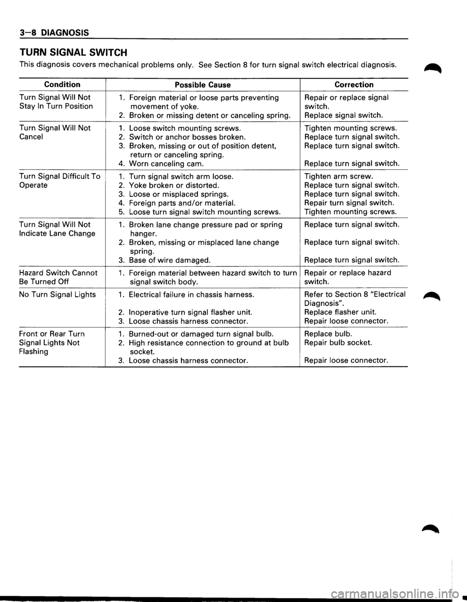
TURN SIGNAL SWITCH
This diagnosis covers mechanical problems only. See Section 8 for turn signal switch electrical diagnosis. ~
Condition Possible Cause Correction
Turn Signal
Will Not 1. Foreign material or loose parts preventing Repair or replace
signal
Stay
In Turn Position movement of yoke. switch.
2. Broken or missing detent or canceling spring. Replace
signal switch.
Turn Signal
Will Not 1. Loose switch mounting screws. Tighten mounting screws.
Cancel
2. Switch or anchor bosses broken. Replace
turn signal switch.
3. Broken, missing or out of position detent, Replace
turn signal switch.
return
or canceling spring.
4. Worn canceling cam. Replace
turn signal switch.
Turn Signal Difficult To
1. Turn signal switch arm loose. Tighten
arm screw.
Operate
2. Yoke broken or distorted. Replace
turn signal switch.
3. Loose or misplaced springs. Replace
turn signal switch.
4. Foreign parts and/or material. Repair
turn signal switch.
5. Loose turn signal switch mounting screws. Tighten mounting screws.
Turn Signal Will Not
1 . Broken lane change pressure pad or spring Replace
turn signal switch.
Indicate Lane Change
hanger.
2. Broken, missing or misplaced lane change Replace
turn signal switch.
spring.
3. Base of wire damaged. Replace
turn signal switch.
Hazard Switch Cannot
1. Foreign material between hazard switch to turn Repair
or replace hazard
Be Turned Off
signal switch body. switch.
No Turn Signal Lights
1. Electrical failure in chassis harness. Refer to Section
8 "Electrical
Diagnosis".
2. Inoperative turn signal flasher unit. Replace
flasher unit.
3. Loose chassis harness connector. Repair
loose connector.
Front or Rear Turn
1. Burned-out or damaged turn signal bulb. Replace
bulb.
Signal Lights
Not 2. High resistance connection to ground at bulb Repair
bulb socket.
Flashing socket.
3. Loose chassis harness connector. Repair
loose connector.
•
Page 375 of 1928
REAR WHEEL ANTILOCK BRAKE SYSTEM 5A3-7
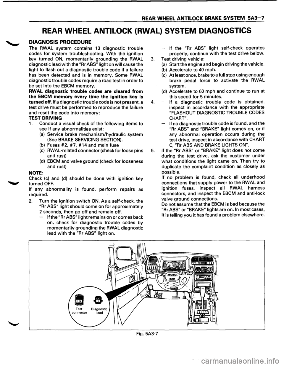
REAR WHEEL ANTILOCK (RWAL) SYSTEM DIAGNOSTICS
DIAGNOSIS PROCEDURE
The RWAL system contains 13 diagnostic trouble
codes
for system troubleshooting. With the ignition
key turned
ON, momentarily grounding the RWAL
diagnostic lead
with the "Rr ABS" light on will cause the
light
to flash out a diagnostic trouble code if a failure
has been detected and is in memory.
Some RWAL
diagnostic trouble codes require a road test in order
to
be set into the EBCM memory.
RWAL diagnostic trouble codes are cleared from
the
EBCM memory every time the ignition key is
turned off. If a diagnostic trouble code is not present, a
test drive
must be performed to reproduce the failure
and reset the code into
memory:
TEST DRIVING
1. Conduct a visual check of the following items to
see if any abnormalities exist:
(a) Service brake mechanism/hydraulic system
(See BRAKE SERVICING SECTION).
(b) Fuses #2, #7, #14 and main fuse
(c) RWAL-related connector (check for loose pins
and rust)
(d) EBCM and valve ground (check for looseness
and rust)
NOTE:
Check
(c) and (d) should be done with ignition key
turned
OFF.
If any abnormality is found, perform repairs as
required.
2. Turn the ignition switch ON. As a self-check, the
"Rr ABS" light should come on for approximately
2 seconds, then go
off and remain off.
If the "Rr ABS" light remains on or comes back
on, check
for diagnostic trouble codes by
momentarily grounding the RWAL diagnostic
lead
with the "Rr ABS" light on. -
If the "Rr
ABS" light self-check operates
properly, continue
with the test drive below.
3. Test driving vehicle:
(a) Start the engine and begin driving the vehicle.
(b) Accelerate to 40 mph.
(c) At least once, brake to a full stop using enough
brake pedal force
to activate the RWAL
system.
(d) Accelerate to 60 mph and continue to run at
this speed
for 5 minutes.
4. If a diagnostic trouble code is obtained.
inspect in accordance
with the appropriate
"FLASHOUT DIAGNOSTIC TROUBLE CODES
CHART".
If
no diagnostic trouble code is found, and the
"Rr ABS" and "BRAKE" light comes on, or if
any abnormal operation occurs during the
test drive, inspect in accordance
with CHART
C, "Rr ABS AND BRAKE LIGHTS ON".
5. If the "Rr ABS" or "BRAKE" light does not come
during the test drive, ask the customer under
what conditions the light came on. Then try to
duplicate the complaint condition
as closely as
possible.
If no problem is found, check all underhood
connections that supply power
to the RWAL and
ignition fuses, inspect
all RWAL harness
connectors, and inspect the
EBCM and anti-lock
valve ground connections.
Do not assume that the
EBCM is bad because the
"Rr ABS" or "BRAKE" lights are on. In most cases,
it is telling you it has found a problem elsewhere.
Fig. 5A3-7
Page 376 of 1928
5A3-8 REAR WHEEL ANTILOCK BRAKE SYSTEM
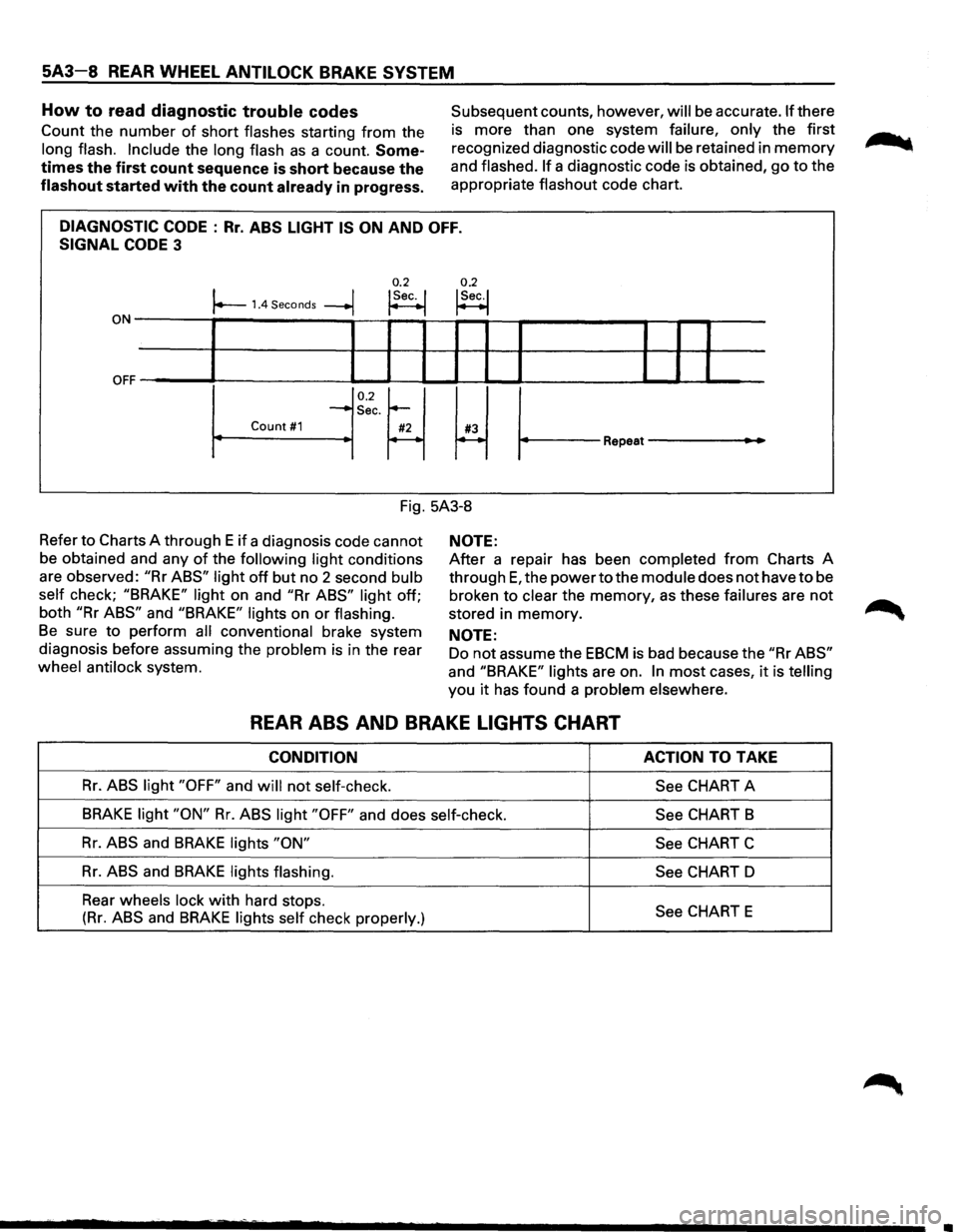
How to read diagnostic trouble codes
Count the number of short flashes starting from the
long flash. Include the long flash as a count. Some
times the first count sequence is short because the
flashout started with the count already in progress.
Subsequent counts, however, will be accurate. If there
is more than one system
failure, only the first
recognized diagnostic code
will be retained in memory
and flashed. If a diagnostic code is obtained, go to the
appropriate
flashout code chart.
DIAGNOSTIC CODE : Rr. ABS LIGHT IS ON AND OFF.
SIGNAL CODE 3
0.2 0.2 I I !Sec. I !Sec.! r--1.4 Seconds --+j ~ t--1
ON-------,~-----------,--~--~~~-r--?-----------~--r--r-----
OFF ~' ----L-1--'-----11 IL....-l.-1 ~I I ______..l__.__l ..____I
0.2~ ~ ~
-Sec.
Count #1 #2 #3 r----~ Repeat---
Fig. 5A3-8
Refer
to Charts A through E if a diagnosis code cannot
be obtained and any
of the following light conditions
are observed:
"Rr ABS" light off but no 2 second bulb
self
check; "BRAKE" light on and "Rr ABS" light off;
both
"Rr ABS" and "BRAKE" lights on or flashing.
Be sure to perform all conventional brake system
diagnosis before assuming the
problem is in the rear
wheel antilock system.
NOTE:
After a repair has been completed from Charts A
through
E, the power to the module does not have to be
broken to
clear the memory, as these failures are not
stored in memory.
NOTE:
Do not assume the EBCM is bad because the "Rr ABS"
and "BRAKE" lights are on. In most cases, it is telling
you it has found a problem elsewhere.
REAR ABS AND BRAKE LIGHTS CHART
CONDITION ACTION TO TAKE
Rr. ABS light "OFF" and will not self-check.
See CHART A
BRAKE light "ON" Rr. ABS light "OFF" and does self-check.
See CHART B
Rr. ABS and BRAKE lights "ON"
See CHART C
Rr. ABS and BRAKE lights flashing.
See CHART D
Rear
wheels lock with hard stops. See CHART E (Rr. ABS and BRAKE lights self check properly.)
Page 380 of 1928
5A3~12 REAR WHEEL ANTILOCK BRAKE SYSTEM
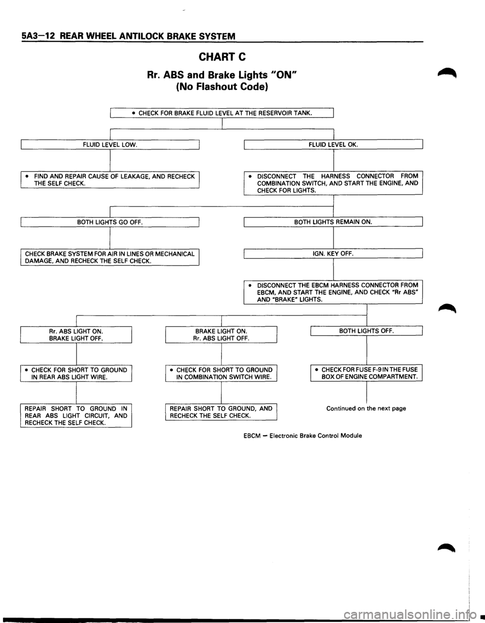
CHART C
Rr. ABS and Brake Lights 110N"
(No Flashout Code}
I • CHECK FOR BRAKE FLUID LEVEL AT THE RESERVOIR TANK.
I
I FLUID LEVEL LOW. I FLUID LEVEL OK.
I
• FIND AND REPAIR CAUSE OF LEAKAGE, AND RECHECK I • DISCONNECT THE HARNESS CONNECTOR FROM THE
SELF CHECK. COMBINATION SWITCH, AND START THE ENGINE, AND CHECK FOR LIGHTS.
I BOTH LIGHTS GO OFF. I BOTH LIGHTS REMAIN ON.
I
CHECK BRAKE SYSTEM FOR AIR IN LINES OR MECHANICAL I IGN. KEY OFF. DAMAGE, AND RECHECK THE SELF CHECK.
• DISCONNECT THE EBCM HARNESS CONNECTOR FROM EBCM, AND START THE ENGINE, AND CHECK uRr ABS" AND UBRAKE" LIGHTS.
I Rr. ABS LIGHT ON.
I
BRAKE LIGHT ON.
I I BOTH LIGHTS OFF. BRAKE LIGHT OFF. Rr. ABS LIGHT OFF.
I • CHECK FOR SHORT TO GROUND I • CHECK FOR SHORT TO GROUND I I
• CHECK FOR FUSE F-91N THE FUSE IN REAR ABS LIGHT WIRE. IN COMBINATION SWITCH WIRE. BOX OF ENGINE COMPARTMENT.
I I REPAIR
SHORT TO GROUND IN I REPAIR SHORT TO GROUND, AND J Continued on the next page REAR ABS LIGHT CIRCUIT, AND RECHECK THE SELF
CHECK.
RECHECK THE SELF CHECK.
EBCM -
Electronic Brake Control Module
•
Page 383 of 1928
REAR WHEEL ANTILOCK BRAKE SYSTEM 5A3-15
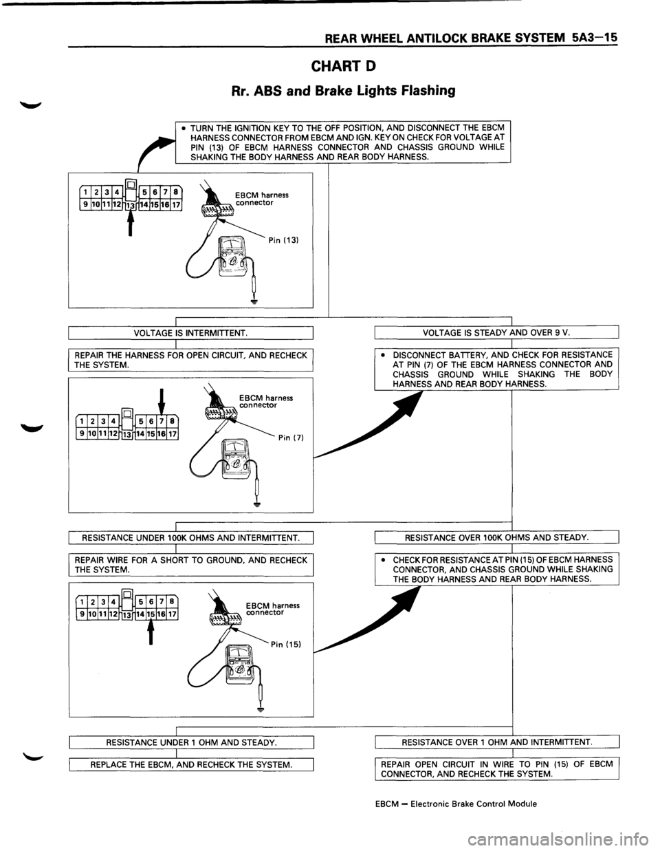
CHART D
Rr. ABS and Brake Lights Flashing
• TURN THE IGNITION KEY TO THE OFF POSITION, AND DISCONNECT THE EBCM HARNESS CONNECTOR FROM EBCM AND IGN. KEY ON CHECK FOR VOLTAGE AT PIN {13) OF EBCM HARNESS CONNECTOR AND CHASSIS GROUND WHILE
SHAKING THE BODY HARNESS AND REAR BODY HARNESS.
REPAIR THE HARNESS FOR OPEN CIRCUIT, AND RECHECK • DISCONNECT BATTERY, AND CHECK FOR RESISTANCE AT PIN {7) OF THE EBCM HARNESS CONNECTOR AND CHASSIS GROUND WHILE SHAKING THE BODY
HARNESS AND REAR BODY HARNESS.
THE SYSTEM.
•
CHECK FOR RESISTANCE AT PIN {15) OF EBCM HARNESS
CONNECTOR, AND CHASSIS GROUND WHILE SHAKING THE BODY HARNESS AND REAR BODY HARNESS.
REPAIR OPEN CIRCUIT
IN WIRE TO PIN {15) CONNECTOR, AND RECHECK THE SYSTEM.
EBCM = Electronic Brake Control Module
Page 384 of 1928
5A3-16 REAR WHEEL ANTILOCK BRAKE SYSTEM
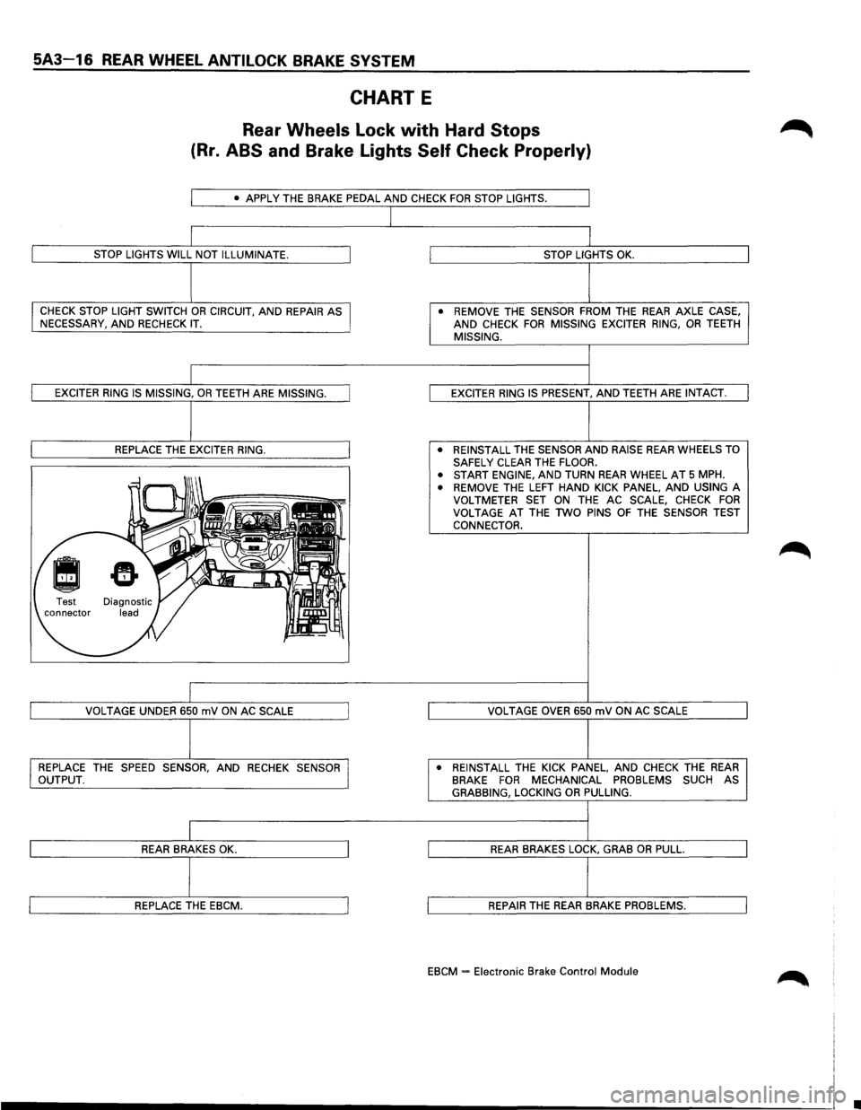
CHART E
Rear Wheels Lock with Hard Stops
(Rr. ABS and Brake Lights Self Check Properly)
• APPLY THE BRAKE PEDAL AND CHECK FOR STOP LIGHTS.
STOP LIGHTS WILL NOT ILLUMINATE.
CHECK STOP LIGHT SWITCH OR CIRCUIT, AND REPAIR AS
NECESSARY, AND RECHECK IT.
EXCITER RING IS MISSING, OR TEETH ARE MISSING.
REPLACE
THE EXCITER RING.
VOLTAGE
UNDER 650 mV ON AC SCALE
REPLACE
THE SPEED SENSOR, AND RECHEK SENSOR
OUTPUT.
REAR BRAKES OK.
REPLACE THE EBCM.
STOP LIGHTS OK.
• REMOVE THE SENSOR FROM THE REAR AXLE CASE, AND CHECK FOR MISSING EXCITER RING, OR TEETH MISSING.
EXCITER
RING IS PRESENT, AND TEETH ARE INTACT.
• REINSTALL
THE SENSOR AND RAISE REAR WHEELS TO
SAFELY CLEAR THE FLOOR.
• START ENGINE, AND TURN REAR WHEEL AT 5 MPH.
• REMOVE THE LEFT HAND KICK PANEL, AND USING A
VOLTMETER SET ON THE AC SCALE, CHECK FOR VOLTAGE AT THE TWO PINS OF THE SENSOR TEST
CONNECTOR.
VOLTAGE
OVER 650 mV ON AC SCALE
• REINSTALL
THE KICK PANEL, AND CHECK THE REAR BRAKE FOR MECHANICAL PROBLEMS SUCH AS GRABBING, LOCKING OR PULLING.
REAR BRAKES LOCK, GRAB OR PULL.
REPAIR THE REAR BRAKE PROBLEMS.
EBCM = Electronic Brake Control Module
•
Page 403 of 1928
REAR WHEEL ANTILOCK BRAKE SYSTEM 5A3-35
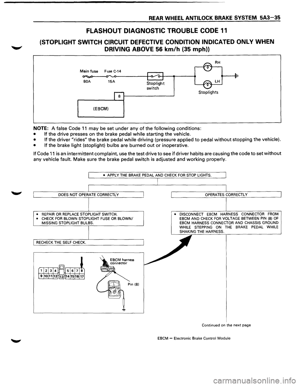
FLASHOUT DIAGNOSTIC TROUBLE CODE 11
(STOPLIGHT SWITCH CIRCUIT DEFECTIVE CONDITION INDICATED ONLY WHEN
DRIVING ABOVE 56 km/h (35 mph))
Main fuse Fuse C-14
BOA 15A
8
(EBCM)
Stoplight
switch Stoplights
NOTE: A false Code 11 may be set under any of the following conditions:
• If the drive presses on the brake pedal while starting the vehicle.
• If
the driver "rides" the brake pedal while driving (pressure applied to pedal without stopping the vehicle).
• If
the brake light (stoplight) bulbs are burned out or inoperative.
If Code 11 is an intermittent complaint, use the test drive to see if driver habits are causing the code to set without
any vehicle fault. Make sure the brake pedal switch is adjusted and working properly.
• REPAIR OR REPLACE STOPLIGHT SWITCH.
• CHECK FOR BLOWN STOPLIGHT FUSE OR BLOWN/ MISSING STOPLIGHT BULBS. •
DISCONNECT EBCM HARNESS CONNECTOR FROM
EBCM AND CHECK FOR VOLTAGE BETWEEN PIN (8) OF EBCM HARNESS CONNECTOR AND CHASSIS GROUND
WHILE STEPPING ON THE BRAKE PEDAL WHILE
SHAKING THE HARNESS.
Continued
on the next page
EBCM = Electronic Brake Control Module
Page 501 of 1928
ENGINE DIAGNOSIS 6-3
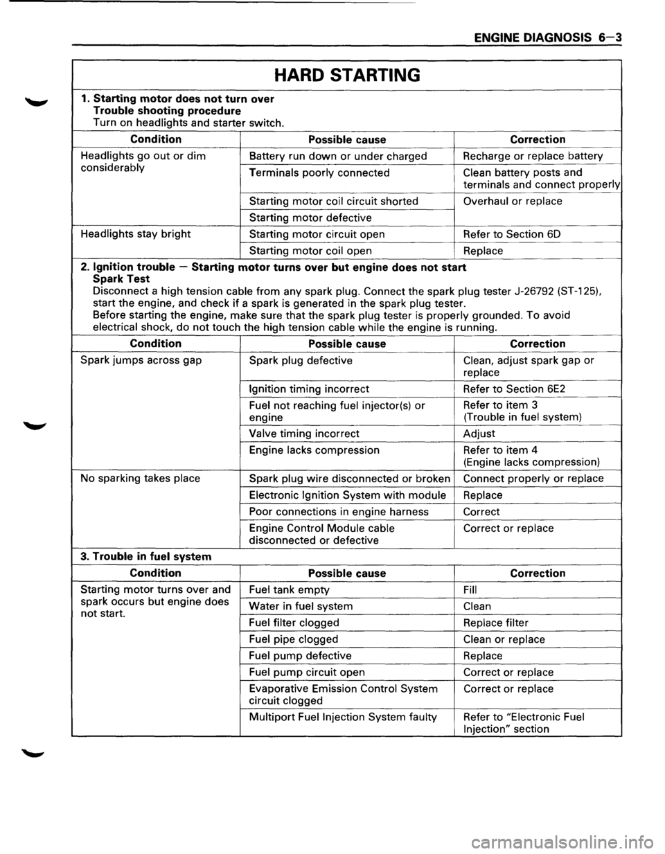
HARD STARTING
1. Starting motor does not turn over
Trouble shooting procedure
Turn on headlights and starter switch.
Condition Possible cause Correction
Headlights go out or dim Battery run down or under charged Recharge or replace battery
considerably
Terminals poorly connected Clean battery posts and
terminals and connect properly
Starting motor coil circuit shorted Overhaul or replace
Starting motor defective
Headlights stay
bright Starting motor circuit open Refer to Section 6D
Starting
motor coil open Replace
2. Ignition trouble -Starting motor turns over but engine does not start
Spark Test
Disconnect a high tension cable from any spark plug. Connect the spark plug tester J-26792 (ST-1 25).
start the engine, and check if a spark is generated in the spark plug tester.
Before starting the engine, make sure
that the spark plug tester is properly grounded. To avoid
electrical shock, do not touch the high tension cable while the engine is running.
Condition Possible cause Correction
Spark jumps across gap
Spark plug defective Clean, adjust spark gap or
replace
Ignition
timing incorrect Refer to Section 6E2
Fuel not reaching fuel injector(s) or Refer to item 3
engine (Trouble
in
fuel system)
Valve
timing incorrect Adjust
Engine
lacks compression Refer to item 4
(Engine
lacks compression)
No sparking takes
place Spark plug wire disconnected or broken Connect properly or replace
Electronic Ignition System with module Replace
Poor connections in engine harness
Correct
Engine Control
Module cable Correct or replace
disconnected or defective
3. Trouble in fuel system
Condition Possible cause Correction
Starting motor turns over and
Fuel tank empty Fill
spark occurs but engine does
not start. Water in fuel system Clean
Fuel filter clogged Replace filter
Fuel pipe clogged Clean or replace
Fuel pump defective
Replace
Fuel
pump circuit open Correct or replace
Evaporative Emission Control System Correct or replace
circuit clogged
Multipart Fuel Injection System faulty Refer to "Electronic Fuel
Injection"
section
Page 657 of 1928
ENGINE ELECTRICAL 601-3
ON-VEHICLE SERVICE
BATTERY CHARGING
Observe the following safety precautions when
charging the battery:
1. Never attempt to charge the battery when the
fluid level is below the lower level line on the
side
of the battery. In this case, the battery
must be replaced.
2. Pay close attention to the battery during the
charging procedure.
Battery charging
should be discontinued or the
rate
of charge reduced if the battery feels hot
to the touch.
Battery charging
should be discontinued or the
rate
of charge reduced if the battery begins to
gas or spew electrolyte from the vent holes.
3. In order to more easily view the hydrometer
blue dot or ring, it may be necessary to jiggle
or tilt the battery.
4. Battery temperature can have a great effect on
battery charging capacity.
5. The sealed battery used on this vehicle may be
either quick-charged or slow-charged in the
same manner
as other batteries.
Whichever method you decide
to use, be sure
that you
completely charge the battery. Never
partially charge the battery.
JUMP STARTING
JUMP STARTING WITH AN AUXILIARY
(BOOSTER)
BATTERY
W CAUTION:
Never push or tow the vehicle in an attempt to
start it.
Serious damage to the emission sys
tem as
well as other vehicle parts will result.
Treat both the discharged battery and the
booster battery
with great care when using
jumper cables. Carefully follow the jump start
ing procedure, being
careful at all times to
avoid sparking.
wwARNING:
Failure to carefully follow the jump starting
procedure
could result in the following:
1. Serious personal injury, particulaly to your
eyes.
2. Property damage from a battery explo
sion, battery acid, or an electrical fire.
3. Damage to the electronic components of
one or both vehicles particularly.
Never expose the battery to an open flame or elec
trical
spark. Gas generated by the battery may catch
fire
or explode.
Remove any rings, watches, or other jewelry before
working around the battery. Protect
your eyes by
wearing
an approved set of goggles.
Never allow battery fluid to come in contact with
your eyes or skin.
Never
allow battery fluid to come in contact with
fabrics or painted surfaces.
Battery
fluid is a highly corrosive acid.
Should battery fluid come in contact with your eyes,
skin, fabric, or a painted surface,
immediately and
thoroughly rinse the affected area with clean tap
water. Never
allow metal tools or jumper cables to come
in contact with the positive battery
terminal, or any
other
metal surface of the vehicle. This will protect
against a short circuit.
Always keep batteries out of the reach of young
children.
JUMP STARTING PROCEDURE
1. Set the vehicle parking brake.
If the vehicle is equipped with an automatic
transmission,
place the selector lever in the
"PARK" position.
If the vehicle is equipped with a manual trans
mission
place the shift lever in the "NEUTRAL"
position.
Turn
"OFF" the ignition.
Turn
"OFF" all lights and any other accessory
requiring
electrical power.
2. Look at the built-in hydrometer.
If the indication area of the built-in hydrometer
is
completely clear, do not try to jump start.
3. Attach the end of one jumper cable to the posi
tive
terminal of the booster battery.
Attach the other end
of the same cable to the
positive
terminal of the discharged battery.
Do not allow the vehicles to touch each other.
This
will cause a ground connection, effectively
neutralizing
the charging procedure.
Be sure that the booster battery has a 12 volt
rating.
4. Attach one end of the remaining cable to the
negative
terminal of the booster battery.
Attach the other end
of the same cable to a
solid engine ground (such as the air condition
ing compressor bracket or the generator
mounting bracket)
of the vehicle with the dis
charged battery.
This ground connection must be at
least 450
mm (18 in) from the battery of the vehicle
whose battery is being charged.
Page 680 of 1928
603 - 4 CHARGING SYSTEM
ON-VEHICLE SERVICE
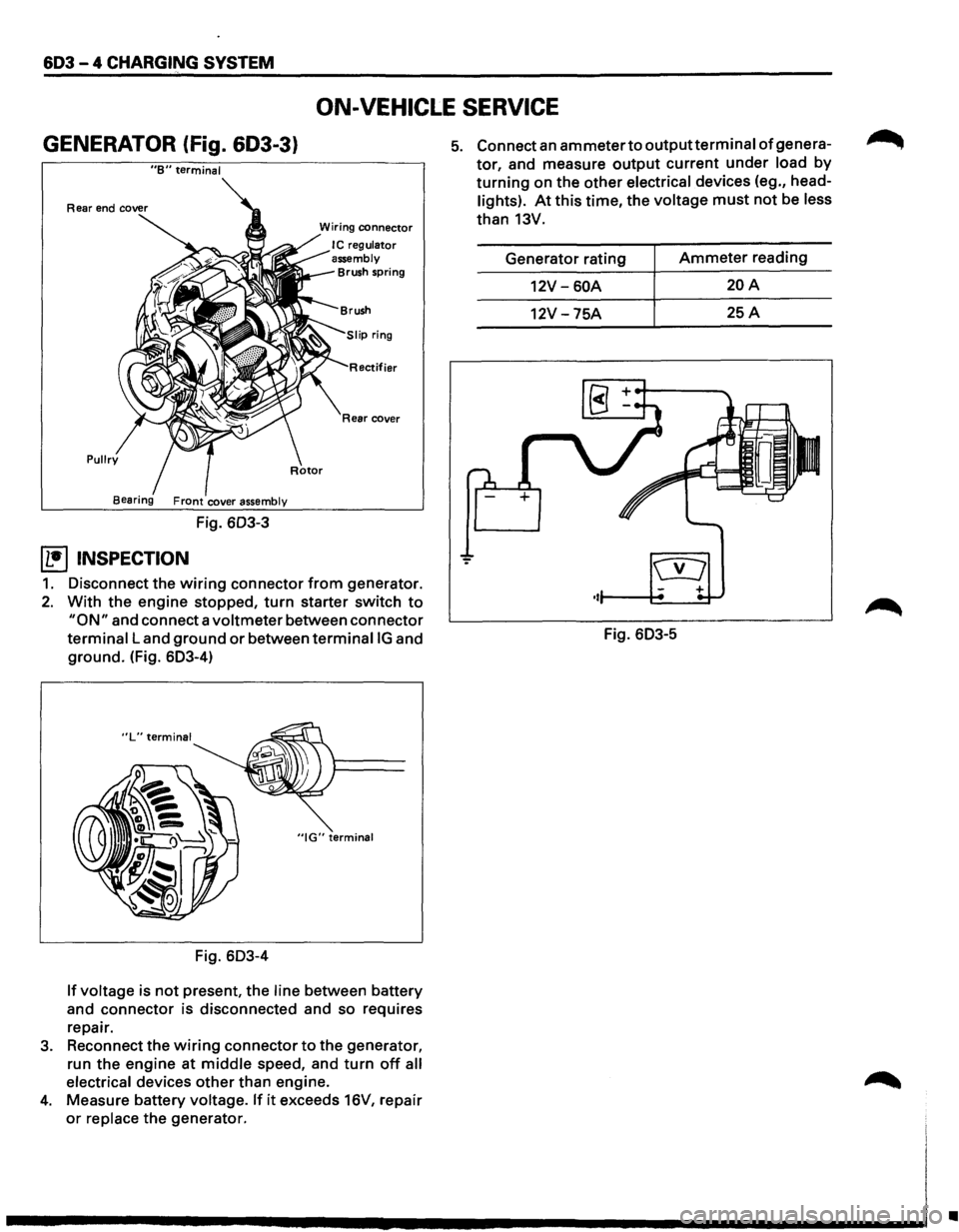
GENERATOR (fig. 603-3}
"B" terminal
Pullry
Fig. 603-3
~ INSPECTION
Wiring connector
I C regulator
assembly
Brush spring
ifier
Rear cover
1. Disconnect the wiring connector from generator.
2. With the engine stopped, turn starter switch to
"ON" and connect a voltmeter between connector
terminal Land ground or between terminaiiG and
ground. (Fig. 603-4)
"IG" terminal
Fig. 603-4
If voltage is not present, the line between battery
and
connector is disconnected and so requires
repair.
3. Reconnect the wiring connector to the generator,
run the
engine at middle speed, and turn off all
electrical
devices other than engine.
4. Measure battery voltage. If it exceeds 16V, repair
or replace the generator.
5. Connect an ammeter to outputterminal of genera
tor, and measure output current under load by
turning on the other electrical devices (eg., head
lights). At this time, the voltage must not be less
than 13V.
Generator rating
Ammeter reading
12V-60A 20A
12V -75A 25A
Fig. 603-5
•