trailer ISUZU TROOPER 1995 Workshop Manual
[x] Cancel search | Manufacturer: ISUZU, Model Year: 1995, Model line: TROOPER, Model: ISUZU TROOPER 1995Pages: 1928
Page 17 of 1928
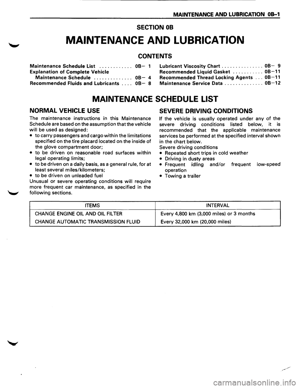
MAINTENANCE AND LUBRICATION OB-1
SECTION 08
MAINTENANCE AND LUBRICATION
CONTENTS
Maintenance Schedule List . . . . . . . . . . . . 08-1
Explanation of Complete Vehicle
Mai-ntenance Schedule . . . . . . . . . . . . . . 08-4
Recommended
Fluids and Lubricants . . . . 08-8
Lubricant Viscosity Chart ............... 08-9
Recommended Liquid Gasket
........... 08-11
Recommended Thread Locking Agents ... 08-11
Maintenance Service Data .............. 08-12
MAINTENANCE SCHEDULE LIST
NORMAL VEHICLE USE
The maintenance instructions in this Maintenance
Schedule are based on the assumption that the vehicle
will
be used as designed:
• to carry passengers and cargo within the limitations
specified on the tire placard located on the inside of
the glove compartment door;
• to be driven on reasonable road surfaces within
legal operating limits;
•
to be driven on a daily basis, as a general rule, for at
least several miles/kilometers;
•
to be driven on unleaded fuel
Unusual
or severe operating conditions will require
more frequent car maintenance,
as specified in the
following sections.
ITEMS
CHANGE ENGINE OIL AND OIL FIL TEA
CHANGE AUTOMATIC TRANSMISSION FLUID
SEVERE DRIVING CONDITIONS
If the vehicle is usually operated under any of the
severe driving conditions
listed below, it is
recommended that the
applicable maintenance
services be performed at the specified
interval shown
in the chart
below.
Severe driving conditions
• Repeated short trips in cold weather
• Driving in dusty areas
• Frequent idling and/or frequent low-speed
operation
• Towing a trailer
INTERVAL
Every 4,800 km (3,000 miles) or 3 months
Every
32,000 km (20,000 miles)
Page 511 of 1928
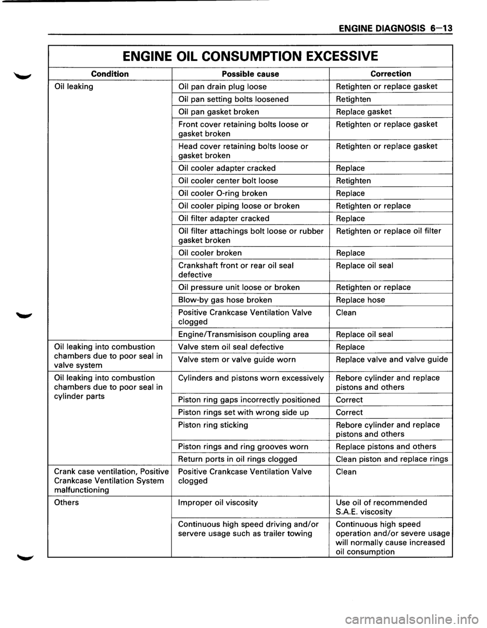
ENGINE DIAGNOSIS 6-13
ENGINE OIL CONSUMPTION EXCESSIVE
Condition Possible cause Correction
Oil leaking
Oil pan drain plug loose Retighten or replace gasket
Oil pan setting bolts loosened Retighten
Oil pan gasket broken Replace gasket
Front cover retaining
bolts loose or Retighten or replace gasket
gasket broken
Head cover retaining
bolts loose or Retighten or replace gasket
gasket broken
Oil cooler adapter cracked Replace
Oil cooler
center bolt loose Retighten
Oil cooler 0-ring broken Replace
Oil cooler
piping loose or broken Retighten or replace
Oil filter
adapter cracked Replace
Oil filter
attachings bolt loose or rubber Retighten or replace oil filter
gasket broken
Oil cooler broken Replace
Crankshaft front or rear oil seal Replace oil seal
defective
Oil pressure unit loose or broken Retighten or replace
Blow-by
gas hose broken Replace hose
Positive Crankcase Ventilation
Valve
Clean
clogged
Engine/Transmisison coupling area Replace oil seal
Oil leaking
into combustion Valve stem oil seal defective Replace
chambers due to poor seal in Valve stem or valve guide worn Replace valve and valve guide valve system
Oil leaking into combustion
Cylinders and pistons worn excessively Rebore cylinder and replace
chambers
due to poor seal in pistons and others
cylinder parts
Piston ring gaps incorrectly positioned
Correct
Piston rings set
with wrong side up
Correct
Piston ring sticking Rebore
cylinder and replace
pistons and others
Piston rings and ring grooves
worn Replace pistons and others
Return ports in
oil rings clogged Clean piston
and replace rings
Crank case ventilation, Positive
Positive Crankcase Ventilation
Valve Clean
Crankcase Ventilation System clogged
malfunctioning
Others Improper oil viscosity
Use oil of recommended
S.A.E. viscosity
Continuous high speed driving
and/or Continuous high speed
servere usage such
as trailer towing operation and/or severe usage
will normally cause increased
oil consumption
Page 888 of 1928
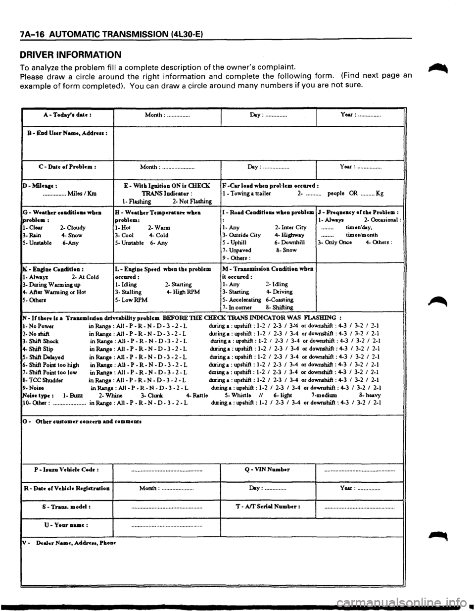
7A-16 AUTOMATIC TRANSMISSION (4L30-E)
DRIVER INFORMATION
To analyze the problem fill a complete description of the owner's complaint.
Please draw a circle around the right information and complete the following form. (Find next page an
example of form completed). You can draw a circle around many numbers if you are not sure.
A-Today' a date : Month: ............... Day:·············· Year: ...............
B-Ead User Name, Address :
C-Dat~ of Problem : Month: ..................... Day: ................. Year: ................
D-Mileaae: E-With Ignirioa. ON ia OIECK F -Car load wheo proHem oceand :
...............
Miles/Km TRANS lodicator : 1 - Towing a trailer 2-.......... people OR ......... Kg
1-Flashing 2-Not Flashing
G-Weather coa.ditiou whea. H-Weather Temperature whea I -Road Cooditioaa wheu problem J-Frequeucy ofthe Problem :
!Problem: problem: : 1-Always 2-Occuional :
1-Clear 2-Cloudy 1-Hot 2-Warm 1-Any 2-Inter City ........ times/day,
3-
Rain 4-Snow 3-Cool 4-Cold 3-Outsid~ City 4- Highway douooo times/month
5- Unstable
6-Any 5-Unstable 6- Any S-Uphill 6-Downhill 3-
Only Once 4-Otheu:
7-Unpaved 8-Snow
9-Others:
IK-EJI&iae Coaditioa : L-Eagiae Spttd whca the problem M-Traasmissiou Coa.diriou wbea
1-Always 2- At Cold occand: it occund:
3-During Warming up 1-Idling 2-Starting 1-Any 2-
Idling
4-After Warming or Hot 3-Stalling 4-HighRPM 3-Starting 4-Driving
5-Others 5-LowRPM 5-Accelerating 6-Coasting
7-Inc:omer 8-Shifting
N-If then b a Trauamiuioa drivcabillty problem BEFORE TIIE CHECK TRANS
INDICATOR WAS FI..ASHING :
I-No Power in Range: All-P-R-N-D-3 -1-L during
a : upshift : 1-2 I 2-3 I 3~4 or downshift : 4-3 I 3-2 I 2-1
2-No shift in Range :All-P-R-N-D-3-2-L during a: upshift
: 1-2 I 2-3 I 3-4 or downshit : 4-3 I 3-2 I 2-1
3- Shift Shock in Range: All-P-R-N-D -3-2-L during a
:upshift : 1-2 I 2-3 I 3-4 or downshift : 4-3 I 3-2 I 2-1
4-Shift Slip in Range: Ali-P-R-N -D-3 -2 -L during a: upshift : 1-2 I 2-3 I 3-4 or downshift : 4-3 I 3-2 I 2-1
5-Shift Delayed in Range : All -P -R-N - D - 3 - 2 - L during a: upshift :
1-2 I 2-3 I 3-4 or downshift : 4-3 I 3-2 I 2-1
6-Shi1 Point too high in Range :All -P-R-N-D-3-2. L during a: upshift:
1-2 I 2-3 I 3-4 or downshift: 4-3 I 3-2 I 2-1
7-Shift Point too low
in Range : All -P -R-N-D-3 -2-L during
a : upshift : 1-2 I 2-3 I 3-4 or downshift : 4-3 I 3-2 I 2-1
S-TCC Shudder in Range :All-P-R. N-D-3-2-L during a: upshift
: 1-2 I 2-3 I 3-4 or downshift : 4-3 I 3-2 I 2-1
9-Noise in Range : All -P -R-N - D - 3 - 2 - L during a: upshift : 1-2 I 2-3 I 3-4 or downshift : 4-3 I 3-2 I 2-1
INolae type: 1-Buzz 2-Whine 3-Clunk 4-Rattle S-Whistle II 6-light 7-medium 8-hoavy
10-Other: ..................... in Range : All -P -R-N - D - 3 - 2 - L during a: upshit :
1-2 I 2-3 I 3-4 or downshift : 4-3 I 3-2 I 2-1
0-Other cDitomer co aura. aad commeats
P •
bUZD Vebiele Code : ooo,0ooooooooooou• .. ouooooooooooooo•••••o•U Q-VIN Number ··················\
··················\
··········
R-Date orVebiclc Regjatratiou Month: ..................... Day: .............. Year: ...............
S • Traua. model: .................... -. ......................... T-Aff Serial Number : uo••••••••••••••••••\
•••oo•oooooooooooooouooo
U-Your aame: ··················\
··················\
··········
y. Dealer Naau, Addn .. , Pbou~
•
Page 889 of 1928
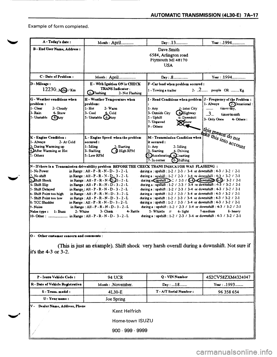
AUTOMATIC TRANSMISSION (4L30-E) 7A-17
Example of form completed.
A-Today's date : Month : April .............. Day: .13 ............. YOM: .1994 ..............
B-Ead U.er Name, Address : Dave Smith
6584, Arlington road
P1ymoutll Ml 48170
USA
C-Date or Problem :
Month : April... ................ Day:.8 ................ You : .1994 ...............
D-Mileace: E-With lguirioa ON is CHECK F -Car load whcu problem occartd:
12230 .. J.@1Km @! TRANS ludicator: 1 -Towing a trailer 2-.. 2 ....... people OR ......... Kg ashing 2-
Not Flashing
G-Weatbtr couditious wbeu H-Weather Temperature wheu I-Road Conditions ""hen problem J-Frequency or the Problem : problem: problem: : 1-Always ~sionaJ :
1-Clear 2- Cloudy 1-Hot 2-Wann 1-Any l.-lltto:r City ........ fio•~s/ y,
3-
Rain 4-Snow 3-Cool ~d 3-Owside City (j}Highway .. .3 ... tim~stmonth 5-Unstable (!).ny S-Unstable 6- y 5-Uphill ti-Downhill 3-Only Once 4-Otb.n: 7-Unpaved )8t.now 9-Others .......___
l!Jis 111P.
K -Euciue Coa.dition : L-Engiue Speed wbea the problem M-Traasmiuioo Condition wheu ~e IJJis 7~~· do l1ot
!-Always 2-At Cold occared: it occared: lJto a
~ing Warming up 1-Idling 2-Starting 1-Any 2-Idling C'collnt
er Warming
or Hot 3-Stalling (3Higt~RPM 3-Starting 4-Driving
5-Others S-Low RPM (~cceleratin~~~~g 7-lr. comer 8-JUftmg
IN-Irtbcrt is a Transmission drive ability problem BEFORE THE CHECK TRANS INVJCATOR WAS FLASHING :
1-NoPower in Range : All -P -R-N-D-3 - 2 - L during a: upshift: 1-2 I 2-3 J 3-4 or downshift: 4-3 I 3-2 / 2-1
~hift inR.ange:AII-P-R-~-0-3-2-L during a : up~hifl : 1-2 I 2-3 ! 3-4 01 uowushifl : ~-3 I 3-2 I 2-1 Shock in Range: AII-P-R-N -~ -2-L during·~-: I 2-3 I (Do~:Qi 3-2 I 2-l 4-Shift Slip in Range : All -P -R-N - D - 3 - 2 - L during a: ups "ft : 1-2 I 2-3 / 3-4 or dov.nshift : 4-3 / 3-2 I 2-1
S-Shift Delayed
in Range,.: All -P -R-N -D-3 -2 - L during
a :upshift : 1-2 I 2-3 I 3-4 or dovmshift : 4-3 I 3-2 I 2-1
6-Shift Point too higJl in Range :All -P-R-N • D-3-2-J.. during a : upshift : 1-2 I 2-3 ! 3-4 or downshift : 4-3 I 3-2 I 2-1 7-Shift Point too low
in Range :All -P-R-N-D-3-2; L during a :upshift : 1-2 I 2-3 I 3-4 or downshift : 4-3 I 3-2 I 2-1
8-TCC Shudder
in Range : All -P - R
- N - D - 3 -2 - L during
a :upshift : 1-2 I 2-3 I 3-4 or downshift : 4-3 I 3-2 I 2-1
9-Noise in Range : All -P -R-N -D-3 -2-L during a :upshift : 1-2 I 2-3 I 3-4 or downshift : 4-3 I 3-2 I 2-1
~oise type: 1-Buzz 2-Whine 3-Clunk 4-lWtle S-Whistle II 6-light 7-medium 8-heavy
10-0thor: ..................... inR.ange:AII-P-R-N-0-3-2-L during
a :upshift : 1-2 I 2-3 I 3-4 or downshift : 4-3 I 3-2 I 2-1
0-Other customer co accra aa.d com meat• :
(This is just an e~ample ). Shift shock very harsh
overall during a downshift. Not sure if
it's the 4-3 or 3-2.
P-huza Vehicle Code : 94 UCR Q -VIN Number 4S2CV58ZXM432404 7
R-Date ofVehieJe Re~stratioa Month : .November. Day: ... .18 ........ Year: . .1993 .........
S -Traaa.. mtldel : 4L30-E T-Aff Serial Number : 96 358 654
U-Yoali'D.ame: Joe Spring
V-Dealer Name, Address, Phooe
Kent Helfrich
Home-town ISUZU
900 -999 -9999
Page 892 of 1928
7 A-20 AUTOMATIC TRANSMISSION (4L30-E)
CHECKING TRANSMISSION FLUID
LEVEL AND CONDITION
Checking fluid level and condition (color and odor)
at
regular intervals will provide early diagnosis
information about the transmission. This inform
ation may be used to correct a condition that, if not
detected early, could result in major transmission
repairs.
IMPORTANT: When new, automatic transmission
fluid is red in color. As the vehicle is driven, the
transmission
fluid will begin to look darker in color.
The
color may eventually appear light brown.
A DARK
brown color with burnt odor may indicate
excessive
fluid deterioration and signal a need for
fluid change.
FLUID LEVEL
When adding
or changing fluid, use only DEXRON
®-Ill.
Refer to the Maintenance and Lubrication (Section 0
of this manual) for maintenance information and
servicing
interval.
\f CAUTION: DO NOT OVERFILL
Overfilling will cause foaming, loss ~f fluid,
abnormal shifting and possible damage to
the transmission.
1. Start engine and drive vehicle until normal AfT
oil operating temperature is reached:
NOTE: The automatic transmission fluid level
must be checked with the vehicle at normal
A/T oil operating temperature: 75 TO 85°C
(167 TO 185°F) MEASURED WITH TECH1 SCAN
TOOL.
Temperature will greatly affect transmission
fluid level.
If the vehicle is not at normal AfT oil operating
temperature and the proper checking
procedures are
not followed, the result could
be a false reading of the fluid level indicator
and
an incorrect adjustment of the fluid level.
2. Park vehicle on level ground.
3. Move gear selector to "Park".
4. Apply parking brake and block wheels.
5. Allow vehicle to idle for 3 minutes with all
accessories turned off.
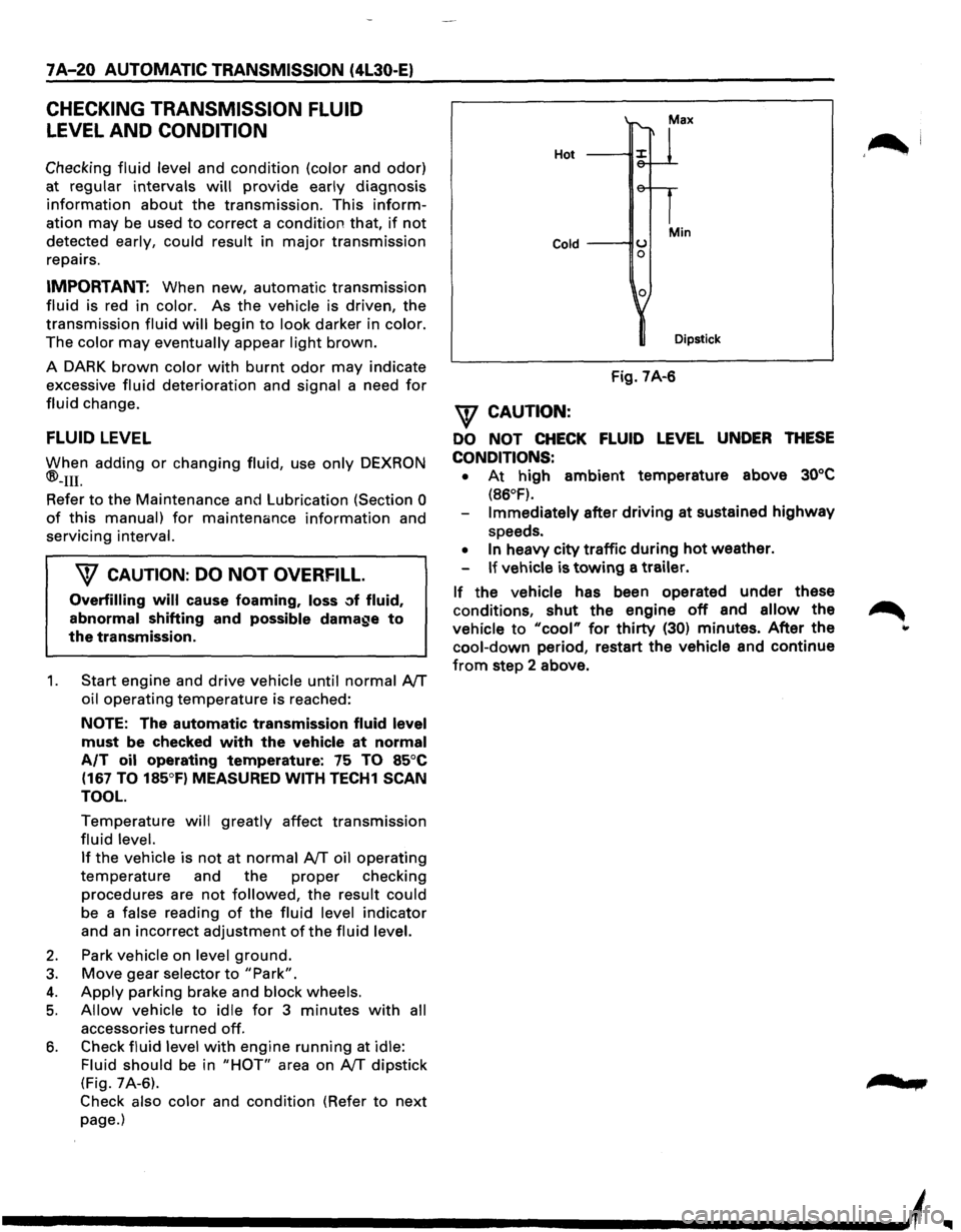
6. Check fluid level with engine running at idle:
Fluid should
be in "HOT" area on AfT dipstick
(Fig. 7A-6).
Check also color and condition (Refer to next
page.)
Hot
Cold ---IIU 0
0
Min
Dipstick
Fig. 7A-6
\f CAUTION:
DO NOT CHECK FLUID LEVEL UNDER THESE
CONDITIONS: •
At high ambient temperature above 30°C
(86°F).
Immediately after driving at sustained highway
speeds.
• In heavy city traffic during hot weather.
If vehicle is towing a trailer.
If the vehicle has been operated under these
conditions,
shut the engine off and allow the
vehicle to "cool" for thirty (30) minutes. After the
cool-down period, restart the vehicle and continue
from step 2 above.
'~I
......
Page 1027 of 1928
... ......,.
AUTOMATIC TRANSMISSION (4L30-E) 7A-155
ON-VEHICLE SERVICE
CHECKING TRANSMISSION FLUID
LEVEL
1. Park the vehicle on level ground.
2. Apply the parking brake.
3. Place the automatic transmission in "Park" and
start the engine.
Allow the engine to idle for
two minutes.
4. With the brakes applied, move the shifter lever
through all the gear ranges, ending in "Park".
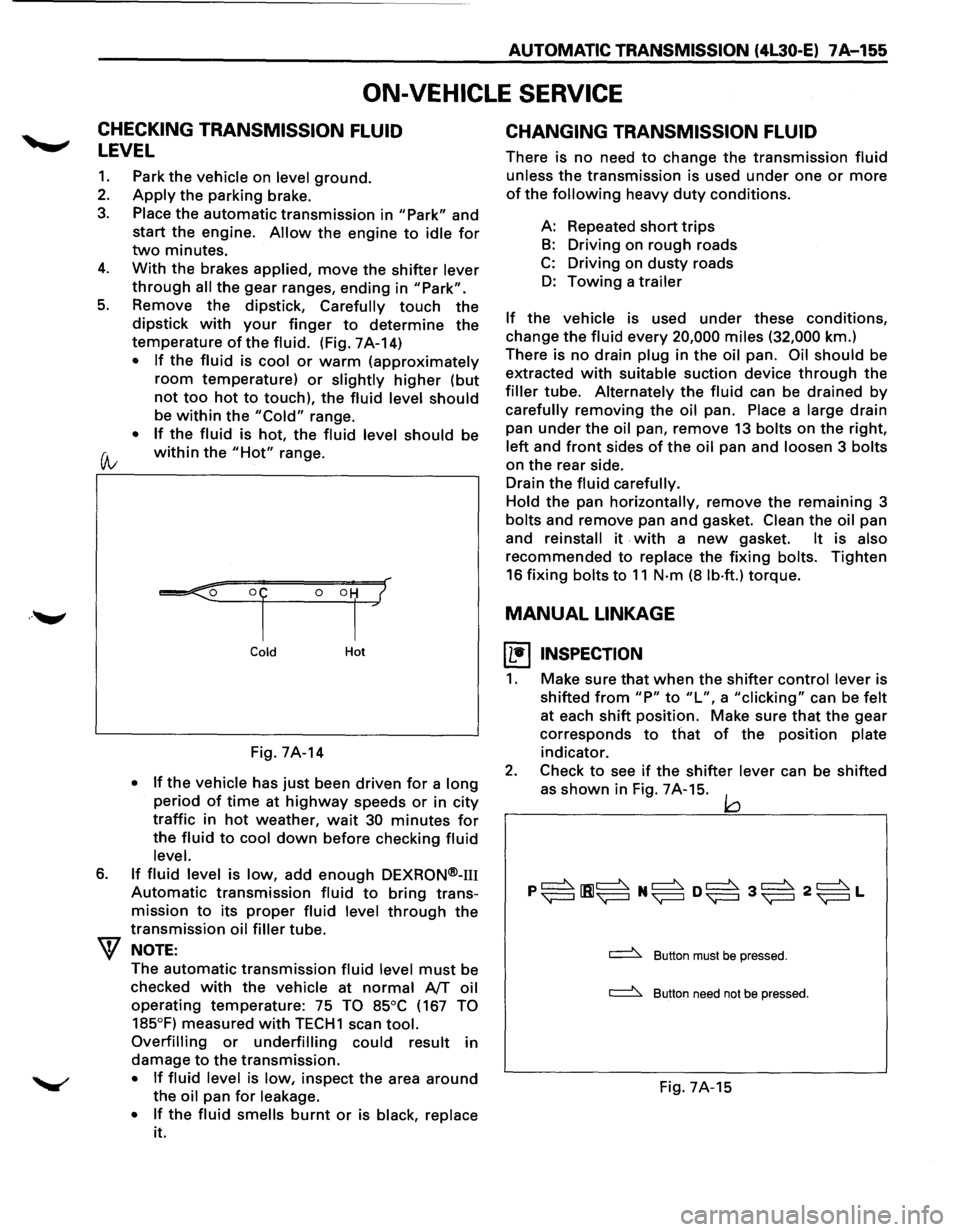
5. Remove the dipstick, Carefully touch the
dipstick with your finger to determine the
temperature of the fluid. (Fig. 7A-14)
• If the fluid is cool or warm (approximately
room temperature) or slightly higher (but
not too hot to touch), the fluid level should
be within the "Cold" range.
• If the fluid is hot, the fluid level should be
(A; within the "Hot" range.
6.
Cold Hot
Fig. 7A-14
• If the vehicle has just been driven for a long
period of time at highway speeds or in city
traffic in hot weather, wait 30 minutes for
the fluid to cool down before checking fluid
level.
If fluid level is low, add enough DEXRON®-m
Automatic transmission fluid to bring trans
mission
to its proper fluid level through the
transmission oil filler tube.
NOTE:
The automatic transmission fluid level must be
checked
with the vehicle at normal AfT oil
operating temperature: 75 TO 85°C (167 TO
185°F)
measured with TECH1 scan tool.
Overfilling or underfilling could result in
damage
to the transmission.
• If fluid level is low, inspect the area around
the oil pan for leakage.
•
If the fluid smells burnt or is black, replace
it.
CHANGING TRANSMISSION FLUID
There is no need to change the transmission fluid
unless the transmission is used under one or more
of the following heavy duty conditions.
A: Repeated
short trips
B: Driving on rough roads
C: Driving on dusty roads
D: Towing a trailer
If the vehicle is used under these conditions,
change the fluid every 20,000 miles (32,000 km.)
There is
no drain plug in the oil pan. Oil should be
extracted
with suitable suction device through the
filler tube. Alternately the fluid can be drained by
carefully removing the oil pan. Place a large drain
pan
under the oil pan, remove 13 bolts on the right,
left and front sides of the oil pan and loosen 3 bolts
on the rear side.
Drain
the fluid carefully.
Hold
the pan horizontally, remove the remaining 3
bolts and remove pan and gasket. Clean the oil pan
and
reinstall it . with a new gasket. It is also
recommended to replace the fixing bolts. Tighten
16 fixing bolts to 11 N·m (8 lb·ft.) torque.
MANUAL LINKAGE
~ INSPECTION
1. Make sure that when the shifter control lever is
shifted
from "P" to "L", a "clicking" can be felt
at each shift position. Make sure that the gear
corresponds
to that of the position plate
indicator.
2. Check to see if the shifter lever can be shifted
as
shown in Fig. 7A-15. jQ
~ Button must be pressed.
~ Button need not be pressed.
Fig. 7A-15
Page 1213 of 1928
CHASSIS ELECTRICAL 8-23
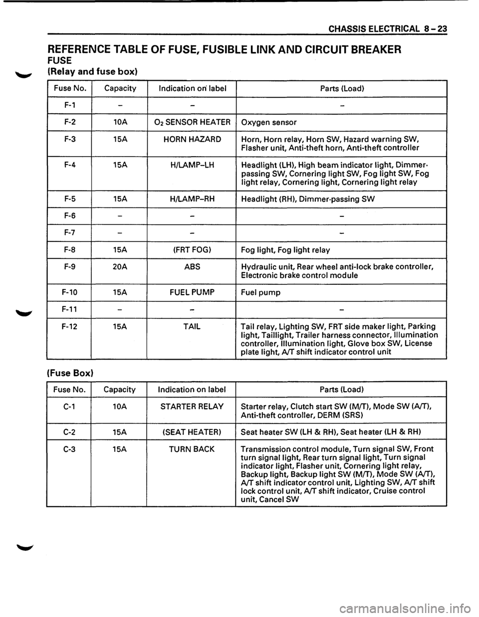
REFERENCE TABLE OF FUSE, FUSIBLE LINK AND CIRCUIT BREAKER
FUSE
'--"' (Relay and fuse box)
Fuse No. Capacity
Indication on· label Parts (Load)
F-1 --
-
F-2 10A 02 SENSOR HEATER Oxygen sensor
F-3 15A HORN HAZARD Horn, Horn relay, Horn SW, Hazard warning SW,
Flasher
unit, Anti-theft horn, Anti-theft controller
F-4 15A
H/LAMP-LH Headlight (LH), High beam indicator light, Dimmer·
passing SW, Cornering light SW, Fog light SW, Fog
light relay, Cornering light, Cornering light relay
F-5 15A
H/LAMP-RH Headlight (RH), Dimmer·passing SW
F-6 ---
F-7 --
-
F-8 15A (FRT FOG) Fog light, Fog light relay
F-9 20A ABS Hydraulic unit, Rear wheel anti-lock brake controller,
Electronic brake control module
F-10 15A FUEL PUMP
Fuel pump
F-11 ---
F-12 15A TAIL Tail
relay, Lighting SW, FRT side maker light, Parking
light, Taillight, Trailer harness connector, Illumination
controller, Illumination light, Glove
box SW, License
plate light, A/T shift indicator control unit
(Fuse Box)
Fuse No. Capacity
Indication on label Parts (Load)
C-1 10A STARTER RELAY Starter relay, Clutch start SW (M/T), Mode SW (A/T),
Anti-theft controller, DERM (SRS)
C-2 15A (SEAT
HEATER) Seat heater SW (LH & RH), Seat heater (LH & RH)
C-3 15A TURN BACK Transmission control module, Turn signal SW, Front
turn signal light, Rear turn signal light, Turn signal
indicator light, Flasher unit, Cornering light relay,
Backup light, Backup light SW (M/T), Mode SW (A/T),
A/T shift indicator control unit, Lighting SW, A/T shift
lock control unit, A/T shift indicator, Cruise control
unit, Cancel SW
Page 1214 of 1928
8-24 CHASSIS ELECTRICAL
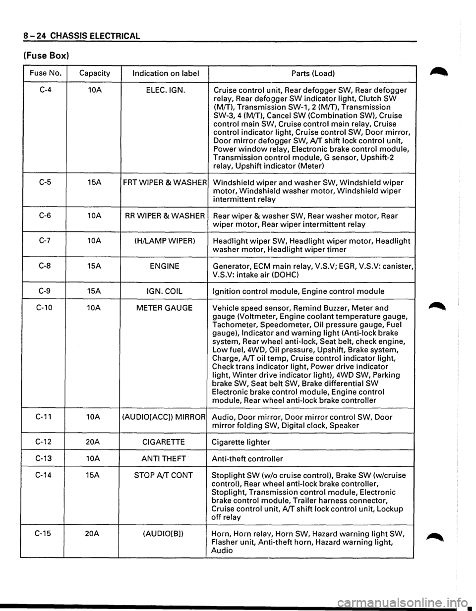
(Fuse Box)
Fuse No.
Capacity Indication on label Parts (Load)
C-4 10A
ELEC.IGN. Cruise control unit, Rear defogger SW, Rear defogger
relay, Rear
defo9ger SW indicator light, Clutch SW
(M{T), Transmission SW-1, 2 (M!T), Transmission
SW-3, 4 (M{T), Cancel
SW (Combination SW), Cruise
control main
SW, Cruise control main relay, Cruise
control indicator light, Cruise control
SW, Door mirror,
Door mirror defogger SW, AfT shift lock control unit,
Power window relay, Electronic brake control module,
Transmission control module, G sensor, Upshift-2
relay, Upshift indicator (Meter)
C-5 15A FRTWIPER &WASHER
Windshield wipt~r and washer SW, Windshield wiper
motor, Windshit~ld washer motor, Windshield wiper
intermittent relay
C-6 10A RR WIPER & WASHER
Rear wiper & washer SW, Rear washer motor, Rear
wiper motor, Rear wiper intermittent relay
C-7 10A (H/LAMP WIPER) Headlight wiper SW, Headlight wiper motor, Headlight
washer motor, Headlight
wiper timer
C-8 15A ENGINE Generator, ECM main relay, V.S.V; EGA, V.S.V: canister,
V.S.V: intake air
(DOHC)
C-9 15A IGN. COIL Ignition control module, Engine control module
C-10 10A METER GAUGE Vehicle speed stmsor, Remind Buzzer, Meter and
gauge
(Voltmeter, Engine coolant temperature gauge,
Tachometer, Speedometer,
Oil pressure gauge, Fuel
gauge),
Indicator and warning light (Anti-lock brake
system, Rear wheel anti-lock, Seat belt, check engine,
Low fuel, 4WD,
Oil pressure, Upshift, Brake system,
Charge,
AfT oil temp, Cruise control indicator light,
Check trans indicator light,
Power drive indicator
light,
Winter drive indicator light), 4WD SW, Parking
brake SW, Seat belt SW, Brake differential SW
Electronic brake control module, Engine control
module, Rear wheel anti-lock brake controller
C-11 10A (AUDIO[ACCJ) MIRROR Audio, Door mirror, Door mirror control SW, Door
mirror folding SW, Digital clock, Speaker
C-12 20A CIGARETTE Cigarette lighter
C-13 10A
ANTI THEFT Anti-theft controller
C-14 15A
STOP AfT CONT Stoplight SW (w/o cruise control), Brake SW (w/cruise
control), Rear wheel anti-lock brake controller,
Stoplight, Transmission control module, Electronic
brake control module, Trailer harness connector,
Cruise control unit,
AfT shift lock control unit, Lockup
off relay
C-15
20A (AUDIO[B]) Horn,
Horn relay, Horn SW, Hazard warning light SW,
Flasher unit, Anti-theft horn, Hazard warning light,
Audio
•
Page 1220 of 1928
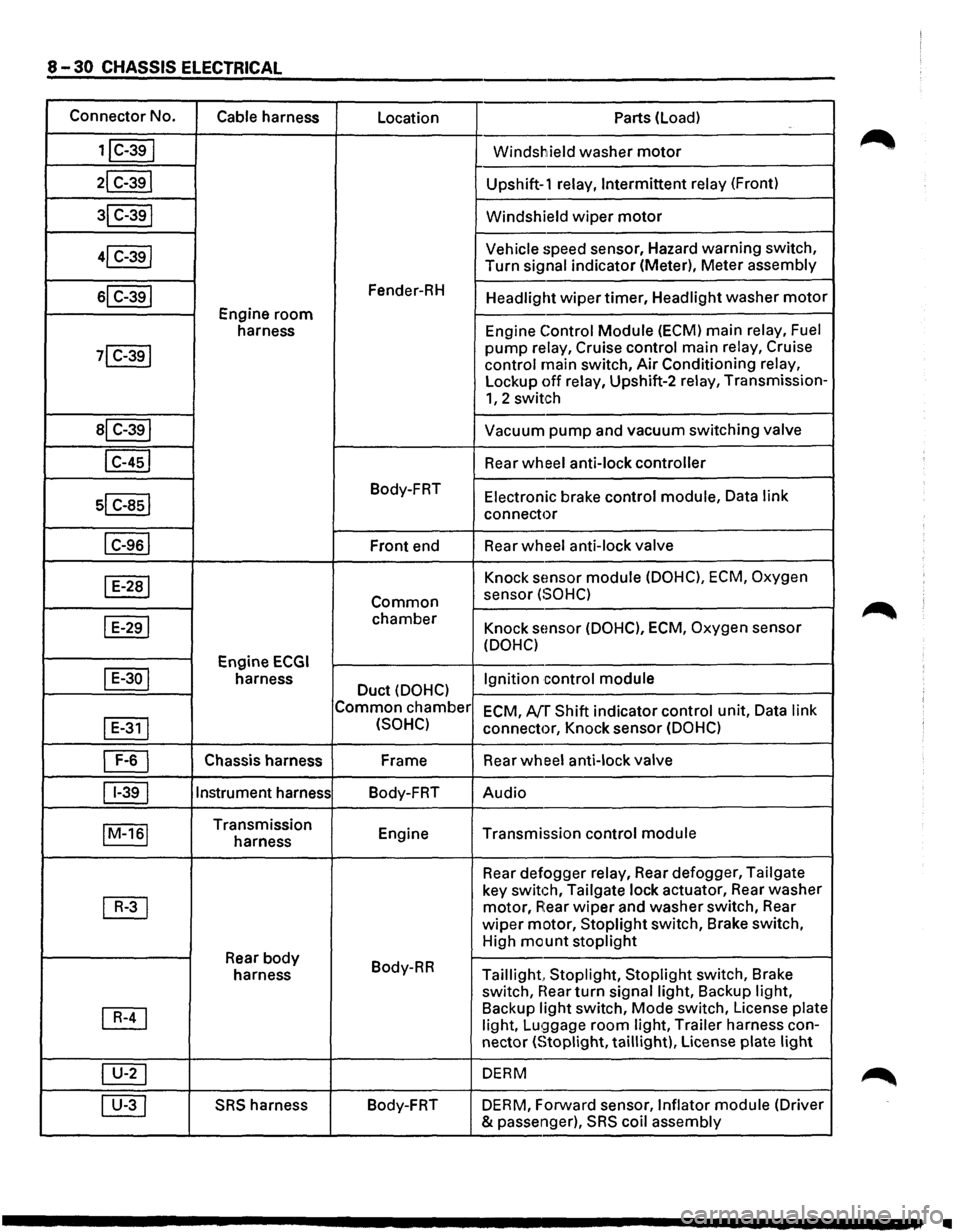
8-30 CHASSIS ELECTRICAL
Connector No.
Cable harness
Location Parts (load)
1jC-39I Windshield washer motor
21 C-391 Upshift-1 relay, Intermittent relay (Front)
31 C-391 Windshield wiper motor
41 C-39j Vehicle speed
sensor, Hazard warning switch,
Turn
signal indicator (Meter), Meter assembly
sl C-391 Fender-RH Headlight wiper timer, Headlight washer motor
Engine room
harness Engine Control Module (ECM)
main relay, Fuel
71 C-391 pump relay, Cruise control main relay, Cruise
control main switch, Air Conditioning relay,
Lockup off relay, Upshift-2 relay, Transmission-
1, 2 switch
al C-391 Vacuum pump and vacuum switching valve
I C-451 Rear wheel anti-lock controller
sl c-asl
Body-FRT Electronic brake control module, Data link
connector
I C-961 Front end Rear wheel
anti-lock valve
I E-281 Knock sEmsor module (DOHC), ECM, Oxygen
Common sensor (SOHC)
I E-291 chamber Knock sensor (DOHC), ECM, Oxygen sensor
(DOHC)
Engine
ECGI
I E-30 I harness Duct (DOHC) Ignition control
module
Common chamber
ECM, AfT Shift indicator control unit, Data link
I
E-311 (SOHC) connector, Knock sensor (DOHC)
~ Chassis harness Frame
Rear wheel anti-lock valve
11-391 Instrument
harness
Body-FRT Audio
IM-161 Transmission
Engine Transmission control module harness
Rear defogger
relay, Rear defogger, Tailgate
~
key switch, Tailgate lock actuator, Rear washer
motor, A:ear wiper and washer switch, Rear
wiper motor, Stoplight switch, Brake switch,
High
mount stoplight
Rear body Body-RR
harness Taillight, Stoplight, Stoplight switch, Brake
switch,
near turn signal light, Backup light,
~
Backup light switch, Mode switch, License plate
light, Lu!;)gage room light, Trailer harness con-
nector
(Stoplight, taillight), License plate light
~ DERM
00 SRS harness Body-FRT
DERM, Forward sensor, Inflator module (Driver
& passenger),
SRS coil assembly
•
Page 1267 of 1928
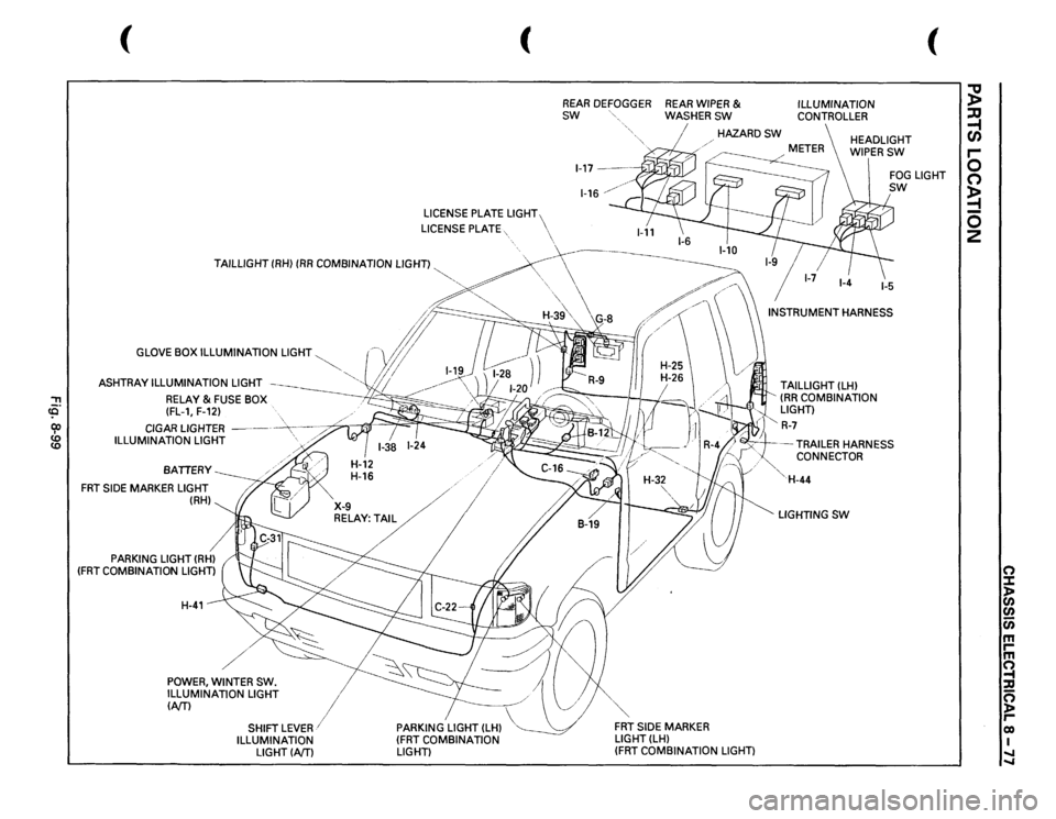
'"T1 (Q cp
GLOVE BOX ILLUMINATION
LIGHT
ASHTRAY ILLUMINATION
LIGHT
RELAY
& FUSE BOX
(FL-1, F-12)
CIGAR LIGHTER
-----
-~----~
ILLUMINATION
LIGHT
'>
./
BATIERY
FRT
SIDE
MARKER LIGHT
(RH)
PARKING
LIGHT (RHl
(FRT
COMBINATION
LIGHT) H-41
/
I
X-9
....
/
RELAY:T/
I
POWER,
WINTER
SW.
ILLUMINATION LIGHT
I
(NT)
1
PARKING
LIGHT (LH)
(FRT
COMBINATION
LIGHT)
SHIFT
LEVER/
ILLUMINATION
LIGHTINTl
(
REAR
DEFOGGER
REAR
WIPER
&
SW
WASHERSW
ILLUMINATION CONTROLLER
(
HAZARDSW
HEADLIGHT WIPERSW
H-32
",,
FRT
SIDE
MARKER
LIGHT(LH)
(FRT
COMBINATION
LIGHT) TAILLIGHT
(LH)
(RR
COMBINATION
LIGHT)
l"
R-7
FOG
LIGHT
sw
-TRAILER
HARNESS
CONNECTOR
'· 'H-44 LIGHTING
SW
;g ;:Q ~ r-0 0 ~ 0 2
0 :::t )> en en c;; m rm ~ :a 0 )> reo I .... ....