lights ISUZU TROOPER 1995 Owner's Guide
[x] Cancel search | Manufacturer: ISUZU, Model Year: 1995, Model line: TROOPER, Model: ISUZU TROOPER 1995Pages: 1928
Page 1277 of 1928
LIGHTING SWITCH
Refer to "HEADLIGHT AND FOG LIGHT" in this
~ section.
ILLUMINATION CONTROLLER
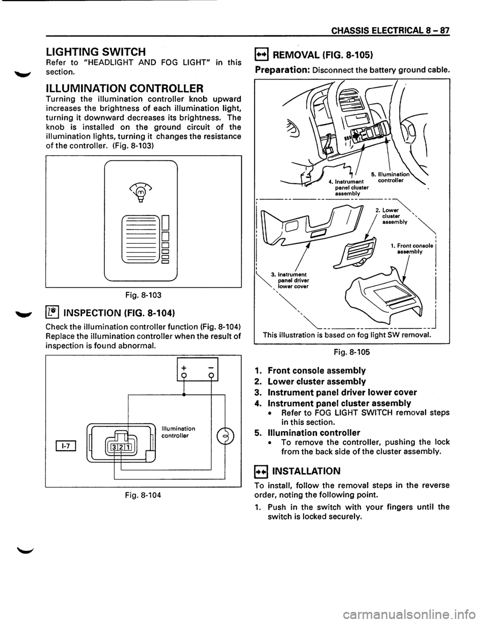
Turning the illumination controller knob upward
increases the brightness
of each illumination light,
turning it downward decreases its brightness. The
knob is
installed on the ground circuit of the
illumination lights, turning it changes the resistance
of the controller. (Fig. 8-103)
Fig. 8-103
....._., ~ INSPECTION (FIG. 8-104)
Check the illumination controller function (Fig. 8-104)
Replace the illumination controller when the result of
inspection is found abnormal.
Fig.
8-104
+
Illumination
controller
CHASSIS ELECTRICAL 8-87
B REMOVAL (FIG. 8-105)
Preparation: Disconnect the battery ground cable.
This illustration is based on fog light SW removal.
Fig. 8-105
1. Front console assembly
2. Lower cluster assembly
3. Instrument panel driver lower cover
4. Instrument panel cluster assembly
• Refer to FOG LIGHT SWITCH removal steps
in this section.
5.
Illumination controller
• To remove the controller, pushing the lock
from the back side of the cluster assembly.
B INSTALLATION
To install, follow the removal steps in the reverse
order, noting the
following point.
1. Push in the switch with your fingers until the
switch is locked securely.
Page 1282 of 1928
I
8 -92 CHASSIS ELECTRICAL I
STOPLIGHT AND REAR DEFOGGER I
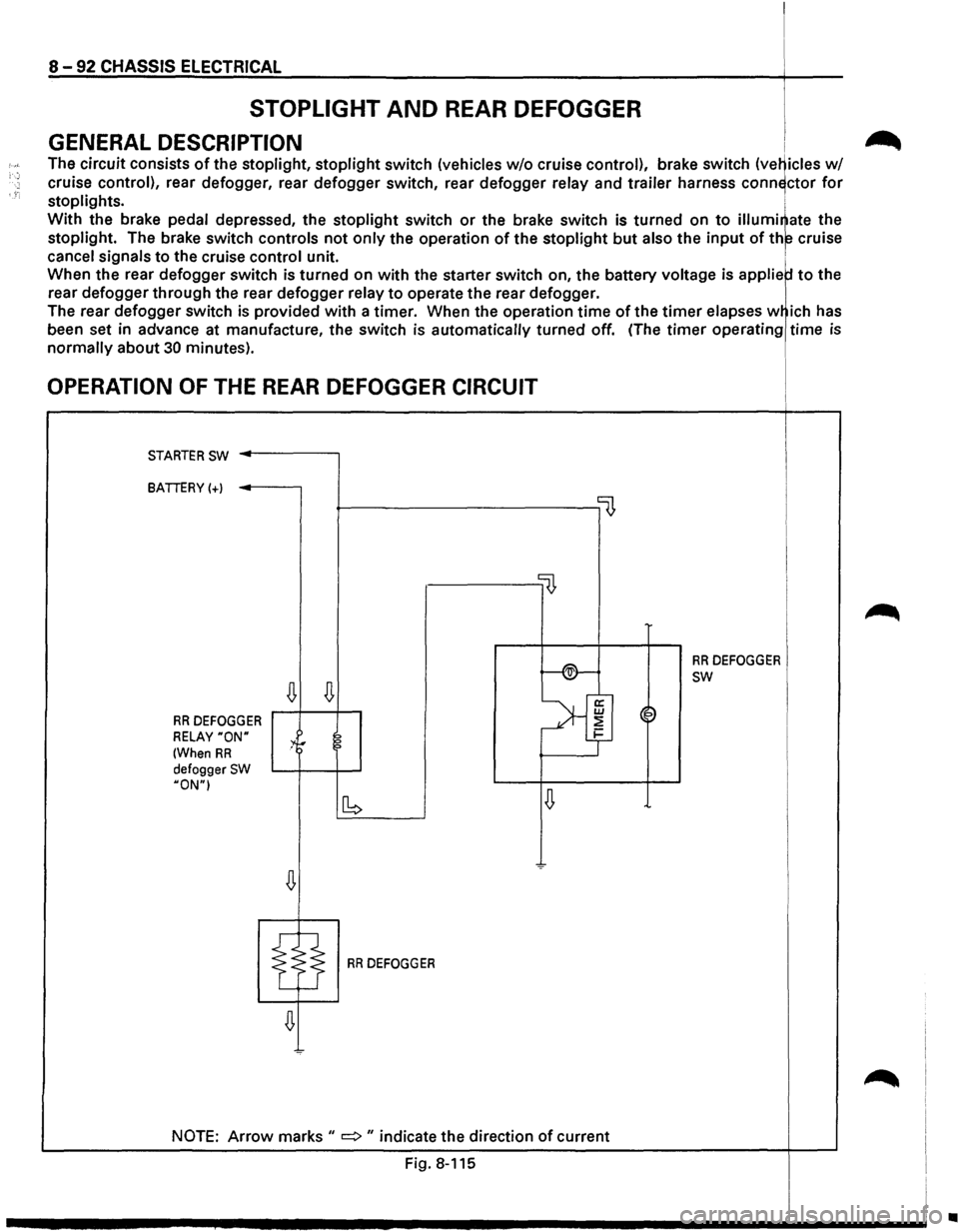
GENERAL DESCRIPTION i .-_
The circuit consists of the stoplight, stoplight switch (vehicles w/o cruise control), brake switch (ve~icles w/
cruise control), rear defogger, rear defogger switch, rear defogger relay and trailer harness conn~ctor for
stoplights. i
With the brake pedal depressed, the stoplight switch or the brake switch is turned on to illumi~ate the
stoplight. The brake switch controls not only the operation of the stoplight but also the input of th~ cruise
cancel signals to the cruise control unit. 1
When the rear defogger switch is turned on with the starter switch on, the battery voltage is applie to the
rear
defogger through the rear defogger relay to operate the rear defogger.
The rear
defogger switch is provided with a timer. When the operation time of the timer elapses w ich has
been set in advance at manufacture,
the switch is automatically turned off. (The timer operating time is
normally about 30 minutes).
OPERATION OF THE REAR DEFOGGER CIRCUIT
STARTER SW ..------,
BATTERY(+)
~----------------0
llJ,
f-®-
RR DEFOGGER
~
SW
~
>'f RR DEFOGGER ~~
RELAY "ON" :4r 2 1-
(When RR ?
defogger SW HON"I
~ [b
RR DEFOGGER
NOTE: Arrow marks II => II indicate the direction of current
Fig. 8-115
~
•
Page 1286 of 1928
8-96 CHASSIS ELECTRICAL
DIAGNOSIS
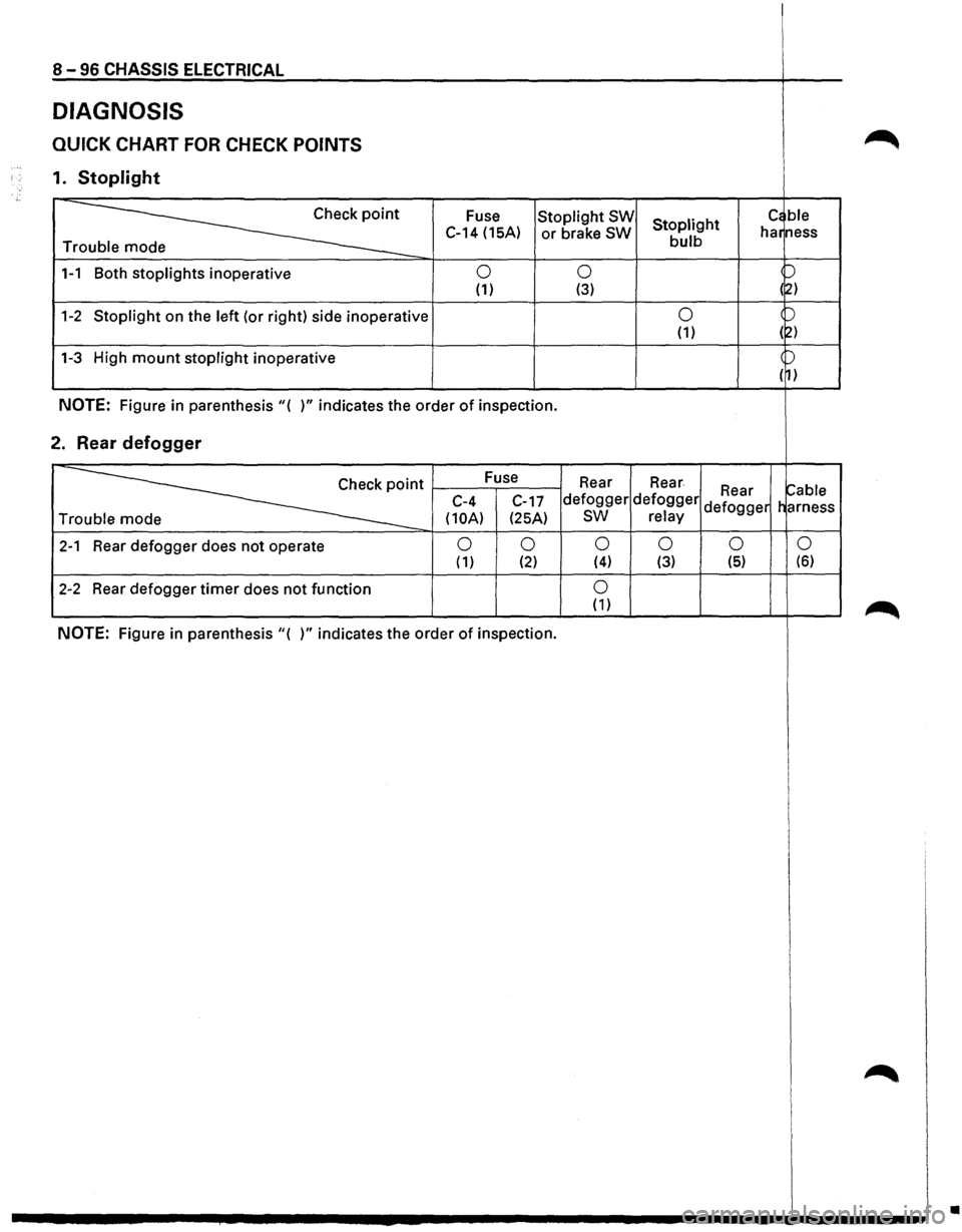
QUICK CHART FOR CHECK POINTS
1. Stoplight
~
Fuse Stoplight SW Stoplight c~ ble
C-14 (15A) or brake SW bulb har
ness
Tr
1-1 Both stoplights inoperative 0 0 p
(1) (3) (~)
1-2 Stoplight on the left (or right) side inoperative 0 )
(1) (2)
1-3 High mount stoplight inoperative )
( 1)
NOTE: Figure in parenthesis"( )" indicates the order of inspection.
2. Rear defogger
~·
Fuse
Rear Rear ~able C-4
C-17 defogger defogger Rear
Tr
(10A) (25A) sw relay defogger
harness
2-1 Rear defogger does not operate 0 0 0 0 0
0 ( 1) (2) (4) (3) (5) (6)
2-2 Rear
defogger timer does not function 0 (1)
NOTE: Figure in parenthesis"( )" indicates the order of inspection.
•
Page 1287 of 1928
CHASSIS ELECTRICAL 8 -97
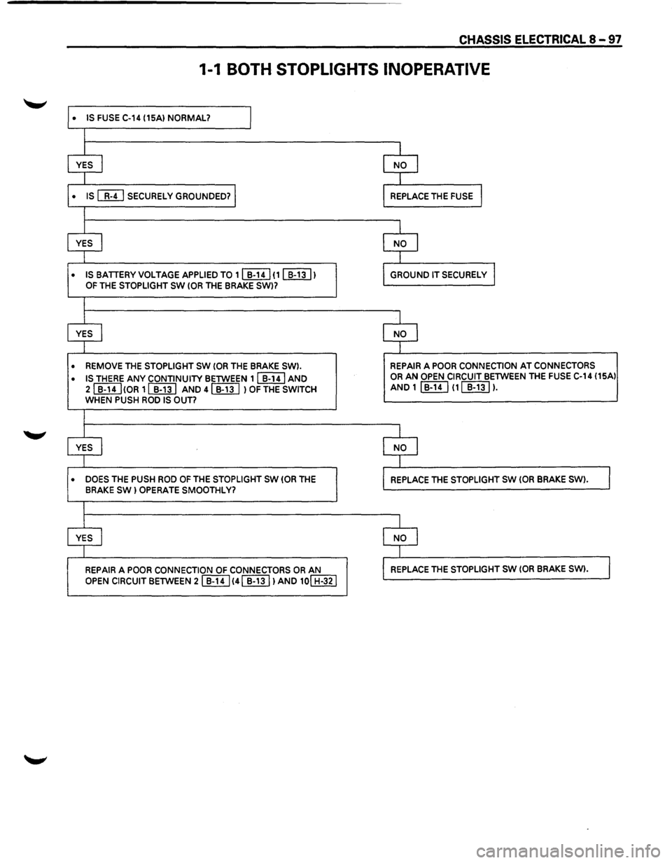
1-1 BOTH STOPLIGHTS INOPERATIVE
• IS FUSE C-14 (15A) NORMAL? I
l
l l
YES I NO l
I I
• IS [MJ SECURELY GROUNDED? I REPLACE THE FUSE l
I
I I
YES I NO I
I 1
• IS BATTERY VOLTAGE APPLIED TO 1 ~ (1 [[ill) GROUND IT SECURELY I OF THE STOPLIGHT SW (OR THE BRAKE SW)7
I
I I
YES I NO l
I I
• REMOVE THE STOPLIGHT SW (OR THE BRAKE SW). REPAIR A POOR CONNECTION AT CONNECTORS
• IS THERE ANY CONTINUITY BETWEEN 11 B-141 AND OR AN OPEN CIRCUIT BETWEEN THE FUSE C-14 (15Al
21 B-14I!OR 11 B-131 AND
4 ~ l OF THE SWITCH AND 1 I B-14 I (1 ~ ).
WHEN PUSH ROO IS OUT?
I
I I
YES I NO I
I T
• DOES THE PUSH ROD OF THE STOPLIGHT SW (OR THE REPLACE THE STOPLIGHT SW (OR BRAKE SW) . 1 BRAKE SW) OPERATE SMOOTHLY?
I
I I
YES I NO I
J -1
REPAIR A POOR CONNECTION OF CONNECTORS OR AN REPLACE THE STOPLIGHT SW (OR BRAKE SW). I OPEN CIRCUIT BETWEEN 21]}!] 141 B-131 lAND 10! H-321
Page 1296 of 1928
8 - 1 06 CHASSIS ELECTRICAL
TURN SIGNAL LIGHT, HAZARD WARNING LIGHT,
CORNERING LIGHT,
BACKUP LIGHT AND HORN
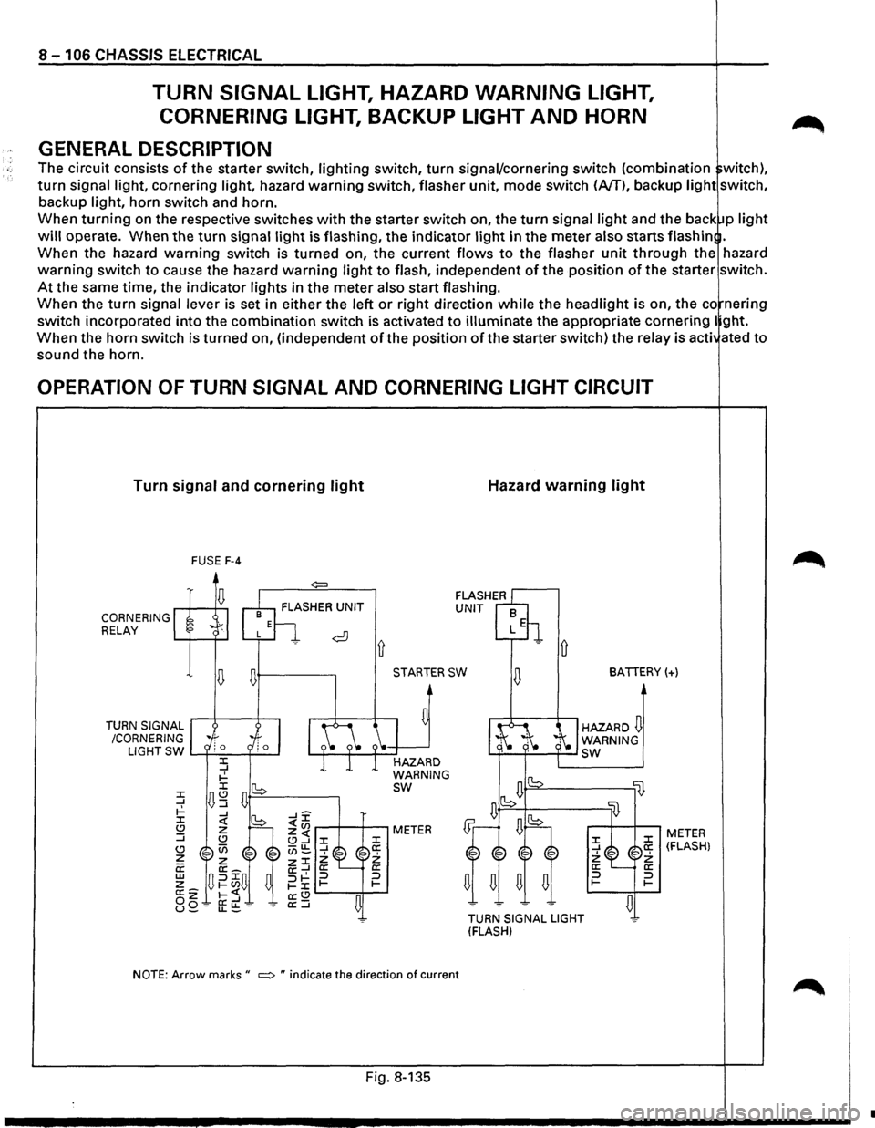
GENERAL DESCRIPTION
The circuit consists of the starter switch, lighting switch, turn signal/cornering switch (combination witch),
turn signal light, cornering light, hazard warning switch, flasher unit, mode switch (A/T), backup light switch,
backup light, horn switch and horn.
When
turning on the respective switches with the starter switch on, the turn signal light and the back p light
will operate. When the turn signal light is flashing, the indicator light in the meter also starts flash in .
When the hazard
warning switch is turned on, the current flows to the flasher unit through the hazard
warning switch to cause the hazard warning light to flash, independent of the position of the starter switch.
At the same time, the indicator lights in the meter also start flashing.
When the
turn signal lever is set in either the left or right direction while the headlight is on, the co nering
switch incorporated
into the combination switch is activated to illuminate the appropriate cornering I ght.
When the horn switch is turned on, (independent
of the position of the starter switch) the relay is acti ated to
sound the horn.
OPERATION OF TURN SIGNAL AND CORNERING LIGHT CIRCUIT
Turn signal and cornering light
CORNERING RELAY
TURN
SIGNAL
/CORNERING FUSE
F-4
~+---------.
Ll G
HT SW L......f-'-=-~--l
STARTER SW
HAZARD
WARNING
sw
NOTE: Arrow marks " ~ " indicate the direction of current
Fig. 8-135
Hazard warning light
D
BATTERY(+)
HAZARD~ WARNING L.f-~'-'----f--' sw
lB
TURN SIGNAL LIGHT
(FLASH)
:z: _J 2: a: :::J 1-
li}
:z: a: 2: a: :::J 1-
~
METER (FLASH)
•
Page 1301 of 1928
CHASSIS ELECTRICAL 8 -111
DIAGNOSIS
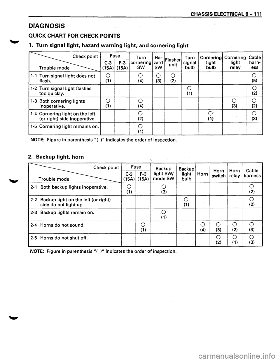
QUICK CHART FOR CHECK POINTS
1. Turn signal light, hazard warning light, and cornering light
~·
Fuse
Turn Ha-Turn Cornering Cornering Cable Flasher C-3 F-3 cornering
zard
unit signal light light harn-
e (15A)
(15A)
sw
sw bulb bulb relay ess
1-1 Turn signal light does not 0
0 0 0 0
flash. (1) (4) (3) (2) (5)
1-2 Turn
signal light flashes 0 0
too quickly. (1) (2)
1-3 Both
cornering lights 0
0 0
0
inoperative. (1)
(4) (3) (2)
1-4 Cornering light on the left 0 0 0
(or
right) side inoperative. (2) (1) (3)
1-5 Cornering light remains on. 0 (1)
NOTE: Figure in parenthesis"{ )"indicates the order of inspection.
2. Backup light, horn
~·
Fuse
Backup Backup
Horn Horn Cable C-3 F-3 light SW/ light Horn switch relay
harness
e {15A) {15A) modeSW bulb
2-1 Both
backup lights inoperative. 0 0 0 (1) {3) {2)
2-2 Backup light on
the left (or right) 0 0
side do not light up {1) (2)
2-3 Backup lights remain on. b {1)
2-4 Horns do not sound. 0 0
0
0 0 {1) (4) {5) {2) (3)
2-5 Horns do not shut off. 0 0 0 {2) (1) (3)
NOTE: Figure
in parenthesis "{ )" indicates the order of inspection.
Page 1304 of 1928
8 -114 CHASSIS ELECTRICAL
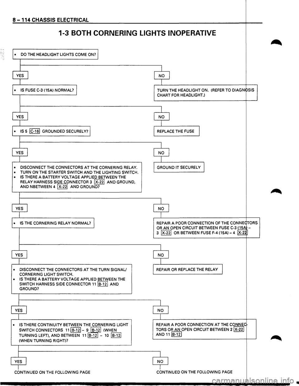
1-3 BOTH CORNERING LIGHTS INOPERATIVE
~ : ...
DO THE HEADLIGHT LIGHTS COME ON? I •
I
YES
I NO I
1
• IS FUSE C-3 {15A) NORMAL? I TURN THE HEADLIGHT ON. {REFER TO DIAGN
PSIS
CHART
FOR HEADLIGHT.)
I
YES
I NO I
I
• IS 5 IC-161 GROUNDED SECURELY? REPLACE THE FUSE I
I
YES
I NO I
I
• DISCONNECT THE CONNECTORS AT THE CORNERING RELAY . GROUND IT SECURELy I
• TURN ON THE STARTER SWITCH AND THE LIGHTING SWITCH .
• IS THERE A BATTERY VOLTAGE APPLIED BETWEEN THE
RELAY
HARNESS SIDE CONNECTOR 3 IX-221 AND GROUND, AND NBETWEEN 4 IX-221 AND GROUND?
~
I
YES
I NO I
I
• IS THE CORNERING RELAY NORMAL? I REPAIR A POOR CONNECTION OF THE CONNEC TORS
OR AN OPEN CIRCUIT BETWEEN FUSE C-3 ~ 3 IX-221 OR BETWEEN FUSE F-4 {15A)-4 X-2~
I
YES
I NO I
I
• DISCONNECT THE CONNECTORS AT THE TURN SIGNAL/ REPAIR OR REPLACE THE RELAY I CORNERING LIGHT SWITCH.
• IS THERE A BATTERY VOLTAGE APPLIED BETWEEN THE
SWITCH HARNESS SIDE CONNECTOR 11IB-12I AND GROUND?
I
YES
I NO I
I
• IS THERE CONTINUITY BETWEEN THE CORNERING LIGHT REPAIR A
POOR CONNECTION AT THE CONNI;,C
SWITCH CONNECTORS
11IB·121-i IB-yl {WHEN TORS OR AN OPEN CIRCUIT BETWEEN 2IX-22I
TURNING LEFT), AND BETWEEN 11 B-12 -10 IB-121 AND 11IB-12I
~ {WHEN TURNING RIGHT)?
I
YES
NO I
cbNTINUED ON THE FOLLOWING PAGE I CONTINUED ON THE FOLLOWING PAGE
..
Page 1306 of 1928
-
8-116 CHASSIS ELECTRICAL
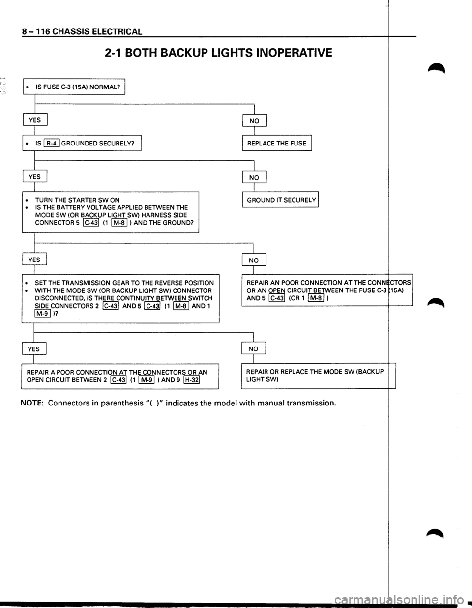
2-1 BOTH BACKUP LIGHTS INOPERATIVE
• IS FUSE C-3 (15A) NORMAL? I
I
I
YES I
I
• IS ~GROUNDED SECURELY? I
I
I
YES I
I
• TURN THE STARTER SW ON
• IS THE BATIERY VOLTAGE APPLIED BETWEEN THE
MODE
SW lOR BACKUP LIGHT SW) HARNESS SIDE coNNECTOR 5 I C-431 11 I M-al >AND THE GROUND?
I
I
YES .J
I
• SET THE TRANSMISSION GEAR TO THE REVERSE POSITION
• WITH
THE MODE SW !OR BACKUP LIGHT SW) CONNECTOR
DISCONNECTED, IS THERE CONTINUITY BETWEEN SWITCH
SIDE
coNNECTORS 2 lc-431 AND 5 I C-431 11 I M-al AND 1 IM-91 )?
I
J
YES I
I
REPAIR A POOR CONNECTION AT THE CONNECTORS OR AN
OPEN CIRCUIT BETWEEN 2 I C-431 ( 1 I M-91 ) AND 9 I H-321
I
NO j
I
REPLACE THE FUSE j
I
NO I
I
GROUND IT SECURELY I
I
NO I
I
REPAIR AN POOR CONNECTION AT THE CONNECTORS
OR AN OPEN CIRCUIT BETWEEN THE FUSE C-3 15A)
AND 5 lc-431 !OR 1 I M-al 1
I
NO I
I
REPAIR OR REPLACE THE MODE SW (BACKUP LIGHTSW)
NOTE: Connectors in parenthesis "( )" indicates the model with manual transmission.
..
Page 1307 of 1928
• •
CHASSIS ELECTRICAL 8 -117
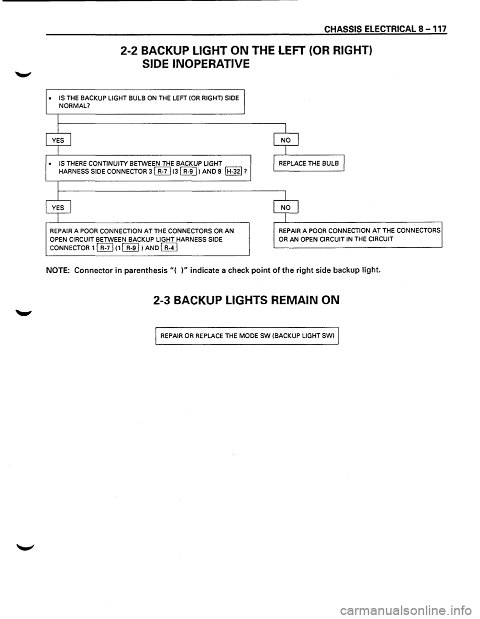
2-2 BACKUP LIGHT ON THE LEFT (OR RIGHT)
SIDE INOPERATIVE
IS THE BACKUP LIGHT BULB ON THE LEFT (OR RIGHT) SIDE NORMAL?
I
I I
YES I NO I
I I
IS THERE CONTINUITY BETWEEN THE BACKUP LIGHT REPLACE THE BULB J HARNESS SIDE CONNECTOR 3 §] (31 R-9 I) AND 9 IH-321?
I
I I
YES j NO I
I I
REPAIR A POOR CONNECTION AT THE CONNECTORS OR AN REPAIR A POOR CONNECTION AT THE CONNECTORS
OPEN CIRCUIT BETWEEN BACKUP LIGHT HARNESS SIDE OR AN OPEN CIRCUIT IN THE CIRCUIT
CONNECTOR 1 [friJ (1 ~)AND [R±J
NOTE: Connector in parenthesis "( )" indicate a check point of the right side backup light.
2-3 BACKUP LIGHTS REMAIN ON
REPAIR OR REPLACE THE MODE SW (BACKUP LIGHT SW)
Page 1318 of 1928
8-128 CHASSIS ELECTRICAL
DOME LIGHT, LUGGAGE ROOM LIGHT, COURTESY LIGHT,
MAP LIGHT, SEAT BELT SWITCH AND WARNING BUZZER
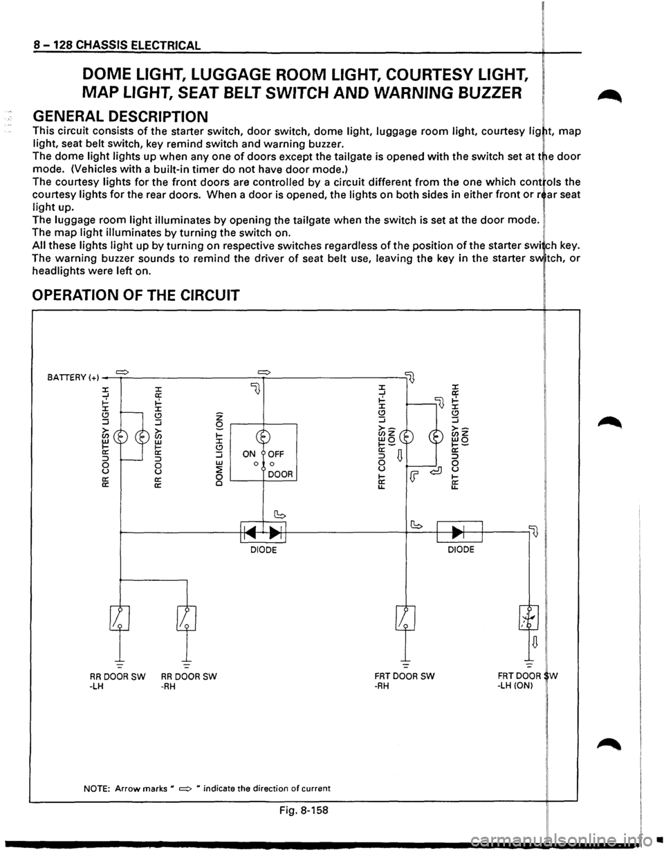
GENERAL DESCRIPTION
This circuit consists of the starter switch, door switch, dome light, luggage room light, courtesy lig t, map
light, seat belt switch, key remind switch and warning buzzer.
The dome
light lights up when any one of doors except the tailgate is opened with the switch set at t e door
mode. (Vehicles with a built-in timer do not have door mode.) !
The courtesy lights for the front doors are controlled by a circuit different from the one which cont ols the
courtesy
lights for the rear doors. When a door is opened, the lights on both sides in either front or r ar seat
light up.
The
luggage room light illuminates by opening the tailgate when the switch is set at the door mode.
The
map light illuminates by turning the switch on.
All these lights light up by turning on respective switches regardless of the position of the starter swi ch key.
The
warning buzzer sounds to remind the driver of seat belt use, leaving the key in the starter sv.. tch, or
headlights were left on.
OPERATION OF THE CIRCUIT
BATIERY (+) _....,.=>..:.__ _________ =>~---------lij
l} :X: :X: ...J a: ~ ~ :X: :X: Q .....__ (.!) ...J :J
~~ ®~ II: li: :::> r----:::> 0 0 u u a: a:
a: a:
z Q r---t----,
~ Go (.!) :J w ON OFF 0 0
~ DOOR 0 '-----+------'
~----------~~~~~~~~lr-l ____________ ,_b __ +-~~~-'--~'---,~ II...... 111"""11 Ill"""' J
-:..._ -=-
RRDOORSW RRDOORSW -LH -RH
DIODE DIODE
-=
FRTDOOR SW -RH
NOTE: Arrow marks u =:> H indicate the direction of current
Fig. 8-158
FRTDOOR W -LH (ON)
•