lights ISUZU TROOPER 1995 User Guide
[x] Cancel search | Manufacturer: ISUZU, Model Year: 1995, Model line: TROOPER, Model: ISUZU TROOPER 1995Pages: 1928
Page 734 of 1928
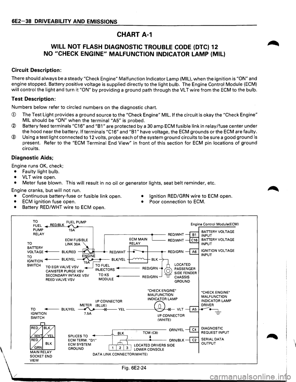
6E2-38 DRIVEABILITV AND EMISSIONS
CHART A-1
WILL NOT FLASH DIAGNOSTIC TROUBLE CODE (DTC) 12
NO "CHECK ENGINE" MALFUNCTION INDICATOR LAMP (MIL)
Circuit Description:
There should always be a steady "Check Engine" Malfunction Indicator Lamp (MIL), when the ignition is "ON" and
engine stopped. Battery positive
voltage is supplied directly to the light bulb. The Engine Control Module (ECM)
will control the light and turn it "ON" by providing a ground path through the VL T wire from the ECM to the bulb.
Test Description:
Numbers below refer to circled numbers on the diagnostic chart.
CD The Test Light provides a ground source to the "Check Engine" MIL. If the circuit is okay the "Check Engine"
MIL should
be "ON" when the terminai"A5" is probed.
® Battery feed terminals "C16" and "B1" are protected by a 30 amp ECM fusible link in relay/fuse center under
the hood near the battery.
If terminals "C16" and "B1" have voltage, the ECM grounds or the ECM are faulty.
® Using a test light connected to 12 volts, probe each of the system ground circuits to be sure a good ground is
present. Refer to the
"ECM Terminal End View" in front of this section for ECM pin locations of ground
circuits.
Diagnostic Aids;
Engine runs OK, check;
• Faulty light bulb.
•
VL T wire open.
• Meter fuse blown. This will result in no oil or generator lights, seat belt reminder, etc.
Engine cranks, but
will not run.
• Continuous battery-fuse or fusible link open. • Ignition RED/GRN wire to ECM open.
• ECM ignition fuse open. • Poor connection to ECM.
• Battery RED/WHT wire to ECM open.
TO FUEL .._..,==~ ,__,__-----, PUMP 15A
RELAY .--------~~-RED/WHT Engine
Control
Module(ECM)
BATIERY VOLTAGE
INPUT
ECM FUSIBLE RED/WHT TO LINK 30A '\.. BATIERY ~ VOLTAGE---BLK!RED ~---.-RED/WHT
TO IGNITION - BLK!YEL ~~~-BLK!YEL --'--'~"'---..__
SWITCH TO EGR VALVE VSV
CANISTER PURGE VSV
SECONDARY INTAKE VSV
REED VALVE VSV TO KS MODULE
LOCATED
PASSENGER
SIDE FENDER CHASSIS GROUND
"CHECK ENGINE"
MALFUNCTION
I/P CONNECTOR INDICATOR LAMP
METER (BLUE)
("";:; TO - BLK!YEL ~(---VEL~(;-VLT IGNITION 7.5A SWITCH
BLK ~ GRN MAIN RELAY
SOCKETEND SPLICES
TO ECM TERM. "D1" ECM SYSTEM GROUND
DATA
LINK CONNECTOR(WHITE)
1/P CONNECTOR
(WHITE)
BA TIERY VOLTAGE INPUT
IGNITION
VOLTAGE INPUT
"CHECK ENGINE"
MALFUNCTION
INDICATOR
LAMP DRIVER
~
DIAGNOSTIC REQUEST INPUT
' VIEW Fig. 6E2-24
./ .................................... __________________________ _
Page 786 of 1928
6E2-90 DRIVEABILITY AND EMISSIONS
INTERMITTENTS
Definition: Problem may or may not turn "ON" the
"Check Engine" malfunction indicator lamp or store
Diagnostic
Trouble Code (DTC).
DO NOT use the DTC charts in "Engine Components/
Wiring Diagrams/Diagnostic
Charts," Section "6E2-A"
for intermittent problem. The fault must be present to
locate the problem. If a fault is intermittent, use of DTC
charts may result in replacement of good parts.
•
• Most intermittent problems are caused by faulty
electrical
connections or wiring. Perform careful
visual/physical
check as described at start of
"Symptoms," Section "6E2-B." Check for:
Poor mating
of the connector halves. or
terminal not fully seated in the connector body
(backed out).
Improperly formed or damaged terminal. All
connector
terminals in the problem circuit
should be carefully reformed or replaced to
insure proper contact tension.
Poor
terminal to wire connection. This
requires removing the
terminal from the
connector body to check. Refer to
SECTION 8
"Wiring Harness Service,"
If a visual/physical check does not find the cause
of the problem, the car can be driven with a
voltmeter connected to a suspected circuit. A
"Scan tool" can also be used to help detect
intermittent conditions. An abnormal
voltage, or
"Scan" tool reading, when the problem occurs,
indicates the
problem may be in that circuit. If the wiring
and connectors check
OK, and a DTC was
stored
for a circuit having a sensor, except for
DTC(s) 44 and 45, substitute a known good sensor
and recheck.
• Loss of DTC memory. To check, disconnect
throttle position (TP) sensor and idle engine until
"Check
Engine" malfunction indicator lamp comes
"ON". DTC 21 should be stored, and kept in
memory when ignition is turned "OFF". If not, the
Engine
Control Module (ECM) is faulty.
•
An intermittent "Check Engine" malfunction
indicator
lamp with no stored DTC may be caused
by:
Ignition coil shorted to ground and arcing at
spark
plug wires or plugs.
"Check
Engine" malfunction indicator lamp
wire to ECM shorted to ground.
Diagnostic
"test" terminal wire to ECM,
shorted to ground.
ECM grounds, refer to ECM wiring diagrams.
• Check for an electrical system interference caused
by a defective
relay, ECM driven solenoid, or
switch. They can cause a sharp electrical surge.
Normally, the problem will occur when the faulty
component is operated.
• Check for improper installation of electrical
options such as lights, 2 way radios, etc.
• Ignition control wires should be routed away from
spark plug wires, electronic ignition (EI) wires, El
housing, coil and generator. Ground wire from
ECM to El should have a good connection.
• If problem has not been found, refer to "ECM
Connector Symptom" charts at the end of
"Symptoms," Section "6E2-B."
HARD START
Definition: Engine cranks OK, but does not start for a
long time. Does eventually run, or may
start
but immediately dies.
PRELIMINARY CHECKS
• Perform the careful visual/physical checks as
described at start of "Symptoms," Section "6E2-
B".
•
Make sure the driver is using the correct starting
procedure.
SENSORS
• CHECK: Engine coolant temperature sensor using
a
"Scan tool", compare engine coolant
temperature with ambient temperature
on
cold engine. -
If engine coolant temperature
readings
is 5 degrees greater than or less than
ambient air temperature on a
cold
engine, check resistance in engine
coolant temperature sensor circuit
or
sensor itself. Compare engine coolant
temperature sensor resistance value
to the "Diagnostic Aids" chart on
DTC
14 chart.
• CHECK: Manifold absolute pressure sensor.
Check for flooding and/or correct sensor
for vehicle.
• CHECK: TP sensor for binding or a high TP sensor
voltage with the throttle closed (should
read between 0.54 volt and 1.25 volts.)
Page 827 of 1928
DRIVEABILITY AND EMISSIONS 6E2-131
CHART C-2C
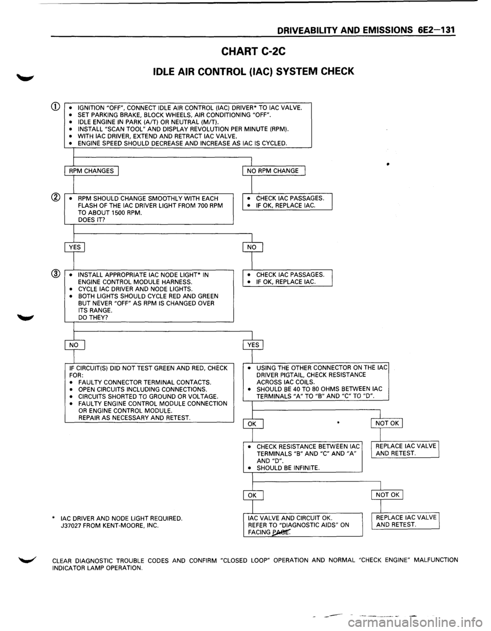
IDLE AIR CONTROL (lAC) SYSTEM CHECK
CD • IGNITION "OFF", CONNECT IDLE AIR CONTROL (lAC) DRIVER* TO lAC VALVE. • SET PARKING BRAKE, BLOCK WHEELS, AIR CONDITIONING "OFF".
• IDLE ENGINE IN PARK (A/T) OR NEUTRAL (MIT). • INSTALL "SCAN TOOL" AND DISPLAY REVOLUTION PER MINUTE (RPM). • WITH lAC DRIVER, EXTEND AND RETRACT lAC VALVE. • ENGINE SPEED SHOULD DECREASE AND INCREASE AS lAC IS CYCLED.
I
1 I • RPM CHANGES I NO RPM CHANGE I
I I • RPM SHOULD CHANGE SMOOTHLY
WITH EACH • CHECK lAC PASSAGES.
I FLASH OF THE lAC DRIVER LIGHT FROM 700 RPM • IF OK, REPLACE lAC.
TO ABOUT 1500 RPM. DOES IT?
I
~ cf
• INSTALL APPROPRIATE lAC NODE LIGHT* IN • CHECK lAC PASSAGES.
l ENGINE CONTROL MODULE HARNESS. • IF OK, REPLACE lAC. ®
• CYCLE lAC
DRIVER AND NODE LIGHTS.
• BOTH LIGHTS SHOULD CYCLE RED AND GREEN BUT NEVER "OFF" AS RPM IS CHANGED OVER
ITS RANGE. DO THEY?
I
cf ~ IF CIRCUIT(S) DID NOT TEST GREEN AND RED, CHECK •
USING THE OTHER CONNECTOR ON THE lAC
FOR: DRIVER
PIGTAIL, CHECK RESISTANCE
•
FAULTY CONNECTOR TERMINAL CONTACTS. ACROSS
lAC COILS.
• OPEN CIRCUITS INCLUDING CONNECTIONS. •
SHOULD BE 40 TO 80 OHMS BETWEEN lAC
• CIRCUITS SHORTED TO GROUND OR VOLTAGE. TERMINALS "A" TO "B" AND "C" TO "D".
• FAULTY ENGINE CONTROL MODULE CONNECTION I OR ENGINE CONTROL MODULE.
~
l REPAIR AS NECESSARY AND RETEST. l NOT OK I .
_l
• CHECK RESISTANCE BETWEEN lAC I REPLACE lAC VALVE I TERMINALS "B" AND "C" AND "A" AND RETEST. AND "D". • SHOULD BE INFINITE.
I
~
l
I NOT OK I
]
AC DRIVER AND NODE LIGHT REQUIRED. * I J lAC VALVE AND CIRCUIT OK. I REPLACE lAC VALVE J 37027 FROM KENT-MOORE, INC. REFER TO "DIAGNOSTIC AIDS" ON AND RETEST. FACING~
~ CLEAR DIAGNOSTIC TROUBLE CODES AND CONFIRM "CLOSED LOOP" OPERATION AND NORMAL "CHECK ENGINE" MALFUNCTION
INDICATOR LAMP OPERATION.
------
Page 883 of 1928

AUTOMATIC TRANSMISSION (4L30-E) 7 A-11
FUNCTIONS OF INPUT /OUTPUT COMPONENTS
Components Function
Speed sensor
Senses rotation
of output shaft and feeds the data to Transmission
(fixed
to transmission (T/M)) Control Module (TCM)
Throttle Senses the extent of throttle valve opening and the speed of the throttle
position sensor (TPS) valve lever motion to open the valve and feeds the data to TCM (fed to
(fixed to engine)
Engine Control Module (ECM) also)
I
Brake Switch (SW) Senses whether the driver has pressed the brake pedal or not and feeds
N (fixed
to brake pedal) the
information to TCM
p Kick-down SW (fixed to Senses whether the driver has pushed the accelerator pedal fully or not
u accelerator pedal) and feeds the information to TCM
T Mode
SW (fixed to T/M) Senses the select lever position and feeds the information to TCM
s Power drive SW Senses whether the driver has selected the power mode and feeds the
I (fixed to front console) information to TCM
G T/M
oil temp. sensor
Senses the T/M oil temperature and feeds the data to TCM
N Engine
coolant Senses the engine cooling water temperature and feeds the data to TCM
A temperature
SW (feeds the signal from ECM)
L
Engine speed
signal Feeds the signals monitoring engine speed to TCM from Ignition Control
Module
(fed to ECM also)
Air conditioning Senses whether the air conditioner has been switched on or not and
information feeds the information
to TCM
On-board diagnostic
input By monitoring the Ground (GND), the location of failure is shown on the
T/M
monitor lamp ("CHECK TRANS") by flashing the diagnostic trouble
code
Winter switch
Senses whether the driver has selected the winter mode, and feeds the
(fixed
to front console) information to TCM
Cruise
controller Downshift takes place when Overdrive OFF signal is received from auto
(Overdrive
OFF signal) cruise control unit
Shift
solenoid Selects shift point and gear position suited to the vehicle running con-s 1-2/3-4, 2-3
dition on the basis of TCM output 0 Band apply solenoid
Controls oil flow suited to the vehicle running condition on the basis of L
E TCM output
0 N
Torque
Converter Controls clutch engagement/disengagement suited to the vehicle
u 0 Clutch solenoid running condition on the basis of TCM output
T I Force motor Adjusts the oil pump delivery pressure to line pressure suited to the p D
(Pressure regulator vehicle running condition on the basis of TCM output u valve) T
Power drive mode lamp
Informs the driver whether the vehicle is in power mode or not
s Winter drive mode lamp Informs the driver whether the vehicle is in winter mode or not
I T/M monitor lamp Informs the driver of failure in the system. It also displays the self diagnosis
G
("CHECK TRANS") code.
N Data Link Connector
(DLC) When connected with TECH 1 or tester, can communicate the data for A
L function
check, etc. (fed to ECM also). When TECH 1 is not connected, can
communicate the
signal for torque management with ECM.
Self-diagnosis connector
When short-circuited with the bipolar connector, the T/M monitor lamp
displays
a failure by code.
ATF warning
lamp Lights when ATF oil temperature rises.
ABS signal When the select lever is at "Reverse" or "L" range, sends a signal to the
ABS controller as one of the ABS control conditions.
Page 1018 of 1928
7A-146 AUTOMATIC TRANSMISSION (4L30-E)
INTERMITTENT CONDITIONS
If the TECH1 displays a diagnostic trouble code as
intermittent, or if after a test drive a DTC does not
reappear though the detection conditions for this
DTC are present: the problem is most likely a faulty
electrical connection or loose wiring. Terminals
and
grounds should always be the prime suspect.
lntermittents rarely occur inside sophisticated
electronic components such
as the TCM.
Use the
DTC information to understand which wires
and sensors are involved.
When an
intermittent problem is encountered,
check suspect circuits for:
(1) Poor terminal to wire connection.
(2) Terminals not fully seated in the connector
body (backed out).
(3) Improperly formed or damaged terminals.
(4) Loose, dirty, or corroded ground connections:
HINT: Any time you have an intermittent in
more than one circuit, check whether the circuits
share a
common ground connection.
(5) Pinched or damaged wires.
(6) Electro-Magnetic Interference (EMI):
HINT:
Check that all wires are properly routed
away from spark plug wires, distributor wires,
coil, and generator. Also check
for improperly
installed electrical options, such as lights, 2-way
radios, etc. Use
the
F3: SNAPSHOT mode of the TECH 1 to help
isolate the cause
of an intermittent fault. The
snapshot
mode will record information before and
after the problem occurs. Set the snapshot
to
"trigger" on the suspect DTC or, if you notice the
reported
symptom during test drive, trigger the
snapshot
manually.
(1) NOTE: When TECH1 is plugged the shifts are
always
done at the maximum pressure. This
means
that if you do SNAPSHOT while driving
you will! notice firm shifts.
After the snapshot has been triggered, command
the TECH1 to play back the flow of data recorded
from each of the various sensors. Signs of an
intermittent fault in a sensor circuit are sudden
unexplainable jump in data values out of the
normal range.
CASE:
problem still not solved GOTO TCM MEM
CAL REPLACEMENT.
•
Page 1231 of 1928
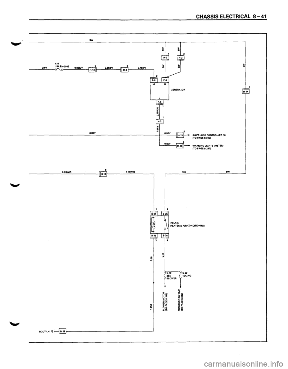
rw
0.85Y
----------------~o~.s~rw~~~-------------l ~13r---------~o-~s~rw~~~--------~
.,
., d
., le '"'
BOOY-LH II
GENERATOR
0.85Y
0.85Y
3W
RELAY;
CHASSIS ELECTRICAL 8-41
SHIFT LOCK CONTROLLER (5) (TO PAGE 8-2021
WARNING LIGHTS (METER) (TO PAGE 8-291 I
5W
HEATER & AIR CONOmONING
~
C-19 C-20 25A 10AAIC SLOWER
~N !~ b(ll ~ol ;~ cr:!l :::><0 ~t :f ~g (g
Page 1249 of 1928
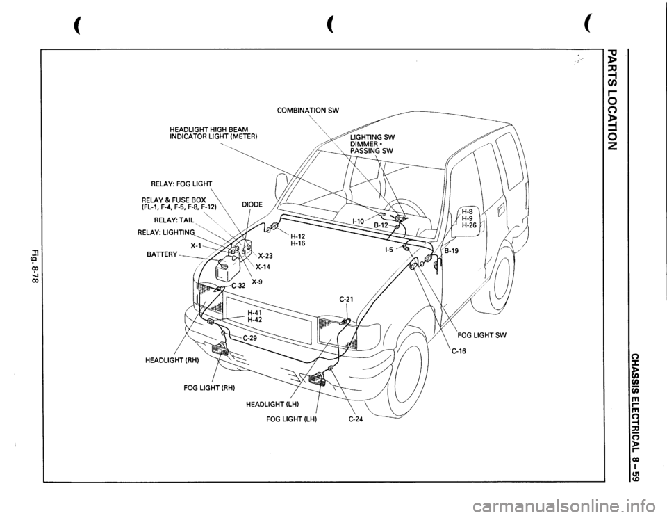
::!! CQ 00 I ....... 00
(
HEADLIGHT
HIGH
BEAM
INDICATOR
LIGHT
(METER)
RELAY:
FOG
LIGHT
RELAY
& FUSE
BOX
(FL-1,
F-4,
F-5, F-8,
F-12)
RELAY:
TAIL
"' "
.
RELAY:
LIGHTING
'"~
'
HEADLIGHT
(RH) FOG
LIGHT
(RH)
(
COMBINATION
SW
"',,,
HEADLIGHT
(LH)
!,--
FOG
LIGHTSW
C-16
(
;g ~ r-0 0 ~ 0 2
(') :I: )II (I)
(I) c;; m rm ~ ::a 0 )> r-eo I m
Page 1250 of 1928
![ISUZU TROOPER 1995 User Guide (")
co
ill
~ (!]
11t
-
I
z
88
::0
iii
en
,
(")
0
5:
~ [I].,.
30B
~~
m
+
c
n
~ciJ~I~~
=i
:I:
FRT
FOG
LIGHT -
LH
)>
r;:;-n
11:::-1
0.85
v
f-1
..
c
(J)
0.56
.r--](/img/61/57183/w960_57183-1249.png "ISUZU TROOPER 1995 User Guide (\")
co
ill
~ (!]
11t
-
I
z
88
::0
iii
en
,
(\")
0
5:
~ [I].,.
30B
~~
m
+
c
n
~ciJ~I~~
=i
:I:
FRT
FOG
LIGHT -
LH
)>
r;:;-n
11:::-1
0.85
v
f-1
..
c
(J)
0.56
.r--")
('")
co
ill
~ (!]
11t
-
I
z
88
::0
iii
en
,
('")
0
5:
~ [I].,.
30B
~~
m
+
c
n
~ciJ~I~~
=i
:I:
FRT
FOG
LIGHT -
LH
)>
r;:;-n
11:::-1
0.85
v
f'-1
..
c
(J)
0.56
.r---
!!!
(J)
,
-)>
Cii
0.56
,..,..,
~
,.....,
I
lo
.,,
G)
m
~
g~
.....
::0
r-
or-
"'
!:-<
.. _
m
., ..
;:
)>
FRT
FOG
LIGHT
SW
J:
:e
n
....
z
s
-1
ILLUMINA TlON
0.5
RIG
J~~~ll~
0.85
G/R
CONTROLLER(3)
o
• RELAY;TAIL(4)
5W
~
::0
(TO PAGE
8-791
(TO PAGE
8-78)
:;;
n
.,
0.5Y/G
0.5Y/G
do
)>
~ ;;;
r-
-
0.85R,IL
:;:
2
~
..
w
!>
OJ
-;::
ill
8~
HIGH
BEAM
INDICATOR
j1!
~~
(METER
I
z:: ~m ~~ "'"' ~:;;
~~
~I
I
~~w
l.
RELAY ;
LIGHTING
0.85Y
.. ;::
fG1
~
...
3R,IB
3W
!W
-
~-
00 I
~o-J...I
u:::J
u;
Lll;;;
I
11-1
1-11
~I
I
'!> -u::.J-
---
1.25W
..
-
-
IJ -<
HEAD
LIGHT
-RH
~
e
1.25
R1Y
~
~
w
-
I~
ANTI
THEfT
0.3V/R
!
O.!V/R
RELAY;
CORNERING(11
CONTROI.LER(181
(TO PAGE 8-1081
(TO PAGE 8-2721
.. w
Of;
I
., .. I
ill
O.SR,IB
I
s;: ~
0.56
~I
; I
I ! I
I
I
I~
~
;=
~
0.3G
ILLUMINATION
LIGHTS
(TO PAGE
8-781
)
)
)
•
Page 1252 of 1928
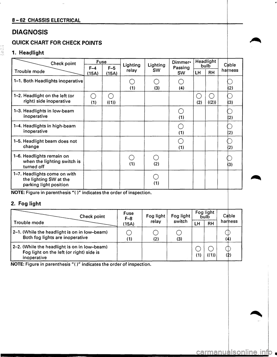
8-62 CHASSIS ELECTRICAL
DIAGNOSIS
QUICK CHART FOR CHECK POINTS ~ )-; '. ·'·• 1. Heaplight 1:·
~
Fuse Lighting Lighting Dimmer• Headlight c ~ble Passing bulb F-4
F-5 relay sw ha ness
T
(15A) (15A) sw LH RH
1-1. Both Headlights inoperative 0 0 0 b (1) (3) (4) 2)
1-2. Headlight on
the left (or 0 0 0
0 b right) side inoperative (1) ((1)) (2) ((2)) 3)
1-3. Headlights in low-beam 0 b inoperative (1) 2)
1-4. Headlights in high-beam 0 b inoperative
(1) 2)
1-5. Headlight beam does not 0 p
change (1) 2)
1-6. Headlights remain on 0 0 b when the lighting switch is
( 1) (2) 3) turned off
1-7. Headlights come on with 0 ~ the lighting SW at the
parking light position (1)
NOTE: Figure in parenthesis"( )" indicates the order of inspection.
2. Fog light
~
Fuse
Fog light Fog light Fog light Cc ble F-8 bulb
(15A) relay switch LH RH har ness Tr
2-1. (While the headlight is on in low-beam) 0 0 0 c ~ Both
fog lights are inoperative (1) (2) (3) ( )
2-2. (While the headlight is
on in low-beam) 0 0 CD Fog light on the left (or right) side is
( 1) ( ( 1)) ( ) inoperative
NOTE: Figure
in parenthesis"()" indicates the order of inspection.
~ -'
..
Page 1253 of 1928
![ISUZU TROOPER 1995 User Guide CHASSIS ELECTRICAL 8-63
1-1. BOTH HEADLIGHTS INOPERATIVE
• IS THE LIGHTING RELAY NORMAL? I
I
I I
YES I NO I
I
I
• IS [[I[] GROUNDED SECURELY? I REPLACE THE LIGHTING RELAY I
I
I
I
YES](/img/61/57183/w960_57183-1252.png "ISUZU TROOPER 1995 User Guide CHASSIS ELECTRICAL 8-63
1-1. BOTH HEADLIGHTS INOPERATIVE
• IS THE LIGHTING RELAY NORMAL? I
I
I I
YES I NO I
I
I
• IS [[I[] GROUNDED SECURELY? I REPLACE THE LIGHTING RELAY I
I
I
I
YES")
CHASSIS ELECTRICAL 8-63
1-1. BOTH HEADLIGHTS INOPERATIVE
• IS THE LIGHTING RELAY NORMAL? I
I
I I
YES I NO I
I
I
• IS [[I[] GROUNDED SECURELY? I REPLACE THE LIGHTING RELAY I
I
I
I
YES I NO I
I I
• IS THE DIODE NORMAL? J GROUND IT SECURELY I
I
I I
YES I NO I
I
I
• DISCONNECT THE LIGHTING SW CONNECTOR REPLACE THE DIODE J • IS THE BATTERY VOLTAGE APPLIED BETWEEN THE HARNESS
SIDE CONNECTOR 1 [[I[j AND GROUND?
I
I I
YES I NO I
I I
• REMOVE THE LIGHTING SW REPAIR A POOR CONNECTION AT THE CONNECTORS
• IS THERE CONTINUITY BETWEEN 1 [[I[] AND 7 ~WHEN OR AN OPEN CIRCUIT BETWEEN THE FUSUBLE LINK SETTING THE LIGHTING SWAT THE HEADLIGHT POSITION? FL-1 (80A) AND 1 ~
I
I I
I YES I NO I
1 I
REPAIR A POOR CONNECTION AT THE CONNECTORS OR AN REPAIR OR REPLACE THE LIGHTING SW I OPEN CIRCUIT BETWEEN THE HARNESS SIDE CONNECTOR 1WI] AND~ (GROUND) OF THE LIGHTING SW