radio ISUZU TROOPER 1995 Workshop Manual
[x] Cancel search | Manufacturer: ISUZU, Model Year: 1995, Model line: TROOPER, Model: ISUZU TROOPER 1995Pages: 1928
Page 3 of 1928
•:1
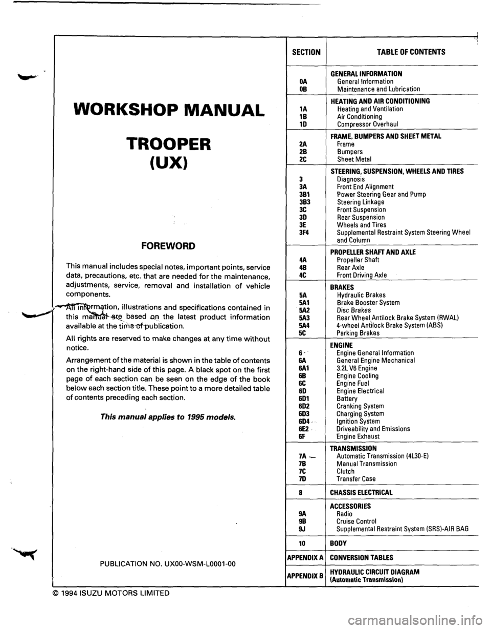
SECTION TABLE OF CONTENTS
. GENERAL INFORMATION OA General Information OB Maintenance and Lubrication
WORKSHOP MANUAL
HEATING AND AIR CONDITIONING 1A Heating and Ventilation
1B Air Conditioning 1D Compressor Overhaul
TROOPER
FRAME, BUMPERS AND SHEET METAL
2A Frame 2B Bumpers
(UX) 2C Sheet Metal
STEERING, SUSPENSION, WHEELS AND TIRES
3 Diagnosis 3A Front End Alignment 3B1 Power Steering Gear and Pump 3B3 Steering Linkage 3C Front Suspension 3D Rear Suspension 3E Wheels and Tires 3F4 Supplemental Restraint System Steering Wheel
FOREWORD and Column
PROPELLER SHAFT AND AXLE 4A Propeller Shaft This manual includes special notes, important points, service 4B Rear Axle
data, precautions, etc. that are needed for the maintenance, 4C Front Driving Axle
adjustments, service, removal and installation of vehicle BRAKES components. 5A Hydraulic Brakes
·~ m rmation, illustrations and specifications contained in 5A1 Brake Booster System
.. _,. 5A2 Disc Brakes ~ this ma. ~-based D.fl the latest product information 5A3 Rear Wheei_Antilock Brake System (RWAL)
available at the tirrHHrl·publication. 5A4 4-wheel Antilock Brake System (ABS)
5C Parking Brakes All rights are reserved to make changes at any time without ENGINE notice. 6· Engine General Information Arrangement of the material is shown in the table of contents &A General Engine Mechanical
on the right-hand side of this page. A black spot on the first 6A1 3.2L VB Engine
page of each section can be seen on the edge of the book &B Engine Cooling
6C Engine Fuel below each section title. These point to a more detailed table &D Engine Electrical of contents preceding each section. 6D1 Battery 6D2 Cranking System
This manual applies to 1995 models. 6D3 Charging System 6D4-Ignition System 6E2. Driveability and Emissions 6F Engine Exhaust
TRANSMISSION 7A-Automatic Transmission (4L30·E) 7B Manual Transmission 7C Clutch 7D Transfer Case
8 CHASSIS ELECTRICAL
ACCESSORIES 9A Radio 9B Cruise Control 9J Supplemental Restraint System (SRS)-AIR BAG
10 BODY
APPENDIX A CONVERSION TABLES PUBLICATION NO. UXOO-WSM-L0001-00
APPENDIXB HYDRAULIC CIRCUIT DIAGRAM (Automatic Transmission)
© 1994 ISUZU MOTORS LIMITED
Page 15 of 1928
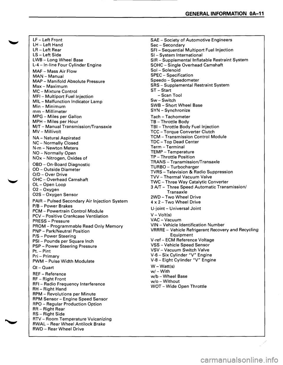
LF -Left Front
LH -Left Hand
LR-Left Rear
LS-Left Side
LWB-Long Wheel Base
L-4-In-line Four Cylinder Engine
MAF-Mass Air Flow
MAN-Manual
MAP-Manifold Absolute Pressure
Max-Maximum
MC-Mixture Control
MFI-Multipart Fuel Injection
MIL-Malfunction Indicator Lamp
Min-Minimum
mm-Millimeter
MPG-Miles per Gallon
MPH-Miles per Hour
M!f-Manual Transmission!fransaxle
MV-Millivolt
NA-Natural Aspirated
NC-Normally Closed
N·m-Newton Meters
NO-Normally Open
NOx-Nitrogen, Oxides of
OBD-On-Board Diagnostic
OD-Outside Diameter
0/D-Over Drive
OHC-Overhead Camshaft
OL-Open Loop
02-Oxygen
02S -Oxygen Sensor
PAIR-Pulsed Secondary Air Injection System
P/B-Power Brakes
PCM-Powertrain Control Module
PCV-Positive Crankcase Ventilation
PRESS-Pressure
PROM-Programmable Read Only Memory
PNP-Park/Neutral Position
P/S-Power Steering
PSI-Pounds per Square Inch
PSP-Power Steering Pressure
Pt.-Pint
Pri -Primary
PWM-Pulse Width Modulate
Ot-Quart
REF-Reference
RF -Right Front
RFI-Radio Frequency Interference
RH-Right Hand
RPM-Revolutions per Minute
RPM Sensor-Engine Speed Sensor
RPO-Regular Production Option
RR-Right Rear
RS-Right Side
RTV-Room Temperature Vulcanizing
RWAL-Rear Wheel Anti lock Brake
RWD-Rear Wheel Drive
GENERAL INFORMATION OA-11
SAE -Society of Automotive Engineers
Sec-Secondary
SFI-Sequential Multipart Fuel Injection
Sl-System International
SIR-Supplemental Inflatable Restraint System
SOHC-Single Overhead Camshaft
Sol -Solenoid
SPEC -Specification
Speedo -Speedometer
SRS-Supplemental Restraint System
ST-Start
-Scan Tool
Sw-Switch
SWB-Short Wheel Base
SYN-Synchronize
Tach-Tachometer
TB
-Throttle Body
TBI-Throttle Body Fuel Injection
TCC-Torque Converter Clutch
TCM-Transmission Control Module
TDC-Top Dead Center
Term-Terminal
TEMP-Temperature
TP-Throttle Position
TRANS-Transmission!fransaxle
TURBO-Turbocharger
TVRS-Television & Radio Suppression
TVV-Thermal Vacuum Valve
TWC-Three Way Catalytic Converter
3
AfT-Three Speed Automatic Transmission/
Transaxle
2WD-Two Wheel Drive
4 x
2-Two Wheel Drive
U-joint-Universal Joint
V-Volt(s)
VAC-Vacuum
VIN-Vehicle Identification Number
VRRRE -Vehicle Refrigerant Recovery and Recycling
Equipment
V-ref-ECM Reference Voltage
VSS-Vehicle Speed Sensor
VSV-Vacuum Switch Valve
V-6-Six Cylinder "V" Engine
V-8-Eight Cylinder "V" Engine
W-Watt(s)
w/-With
w/b -Wheel Base
w/o -Without
WOT-Wide Open Throttle
Page 786 of 1928
6E2-90 DRIVEABILITY AND EMISSIONS
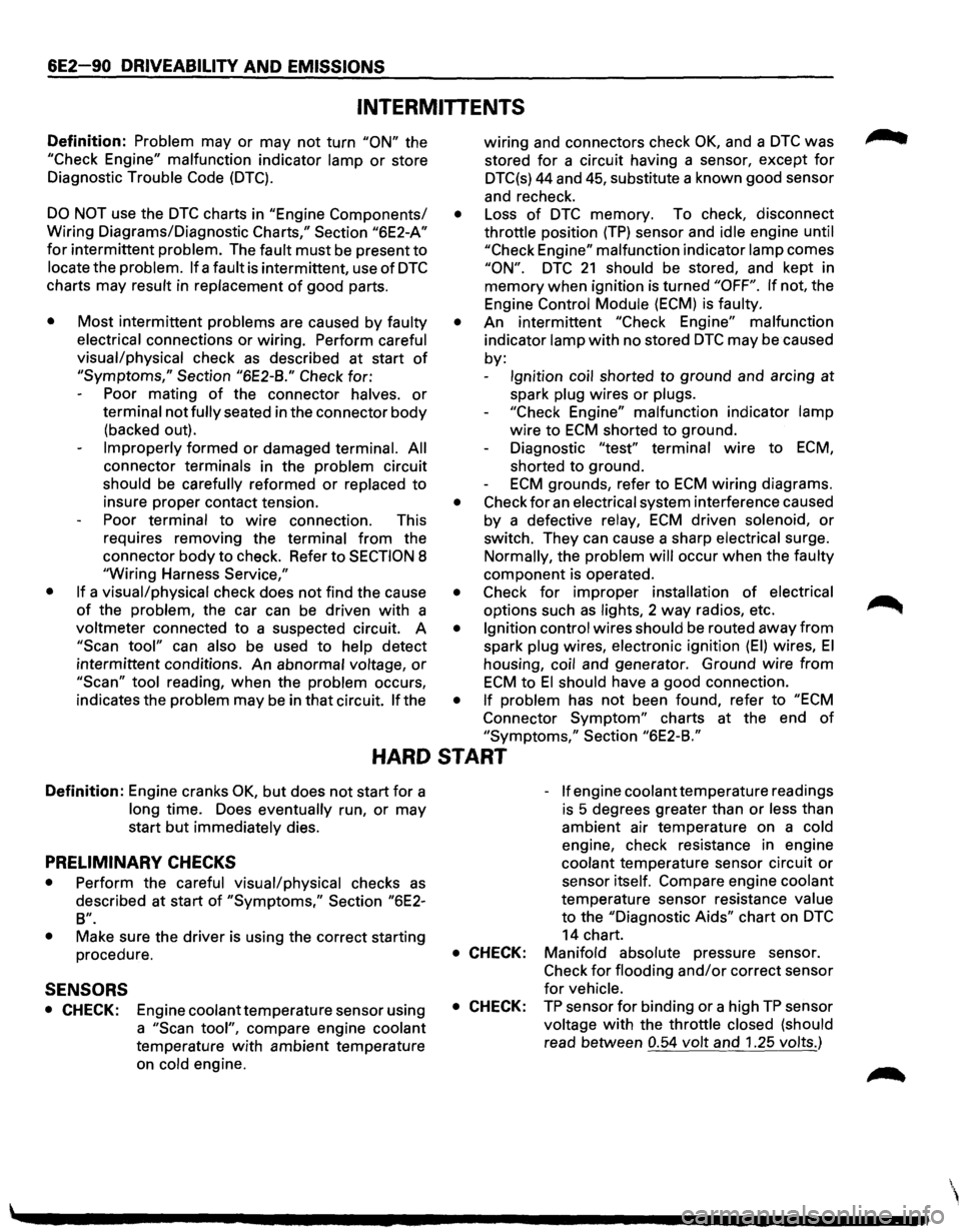
INTERMITTENTS
Definition: Problem may or may not turn "ON" the
"Check Engine" malfunction indicator lamp or store
Diagnostic
Trouble Code (DTC).
DO NOT use the DTC charts in "Engine Components/
Wiring Diagrams/Diagnostic
Charts," Section "6E2-A"
for intermittent problem. The fault must be present to
locate the problem. If a fault is intermittent, use of DTC
charts may result in replacement of good parts.
•
• Most intermittent problems are caused by faulty
electrical
connections or wiring. Perform careful
visual/physical
check as described at start of
"Symptoms," Section "6E2-B." Check for:
Poor mating
of the connector halves. or
terminal not fully seated in the connector body
(backed out).
Improperly formed or damaged terminal. All
connector
terminals in the problem circuit
should be carefully reformed or replaced to
insure proper contact tension.
Poor
terminal to wire connection. This
requires removing the
terminal from the
connector body to check. Refer to
SECTION 8
"Wiring Harness Service,"
If a visual/physical check does not find the cause
of the problem, the car can be driven with a
voltmeter connected to a suspected circuit. A
"Scan tool" can also be used to help detect
intermittent conditions. An abnormal
voltage, or
"Scan" tool reading, when the problem occurs,
indicates the
problem may be in that circuit. If the wiring
and connectors check
OK, and a DTC was
stored
for a circuit having a sensor, except for
DTC(s) 44 and 45, substitute a known good sensor
and recheck.
• Loss of DTC memory. To check, disconnect
throttle position (TP) sensor and idle engine until
"Check
Engine" malfunction indicator lamp comes
"ON". DTC 21 should be stored, and kept in
memory when ignition is turned "OFF". If not, the
Engine
Control Module (ECM) is faulty.
•
An intermittent "Check Engine" malfunction
indicator
lamp with no stored DTC may be caused
by:
Ignition coil shorted to ground and arcing at
spark
plug wires or plugs.
"Check
Engine" malfunction indicator lamp
wire to ECM shorted to ground.
Diagnostic
"test" terminal wire to ECM,
shorted to ground.
ECM grounds, refer to ECM wiring diagrams.
• Check for an electrical system interference caused
by a defective
relay, ECM driven solenoid, or
switch. They can cause a sharp electrical surge.
Normally, the problem will occur when the faulty
component is operated.
• Check for improper installation of electrical
options such as lights, 2 way radios, etc.
• Ignition control wires should be routed away from
spark plug wires, electronic ignition (EI) wires, El
housing, coil and generator. Ground wire from
ECM to El should have a good connection.
• If problem has not been found, refer to "ECM
Connector Symptom" charts at the end of
"Symptoms," Section "6E2-B."
HARD START
Definition: Engine cranks OK, but does not start for a
long time. Does eventually run, or may
start
but immediately dies.
PRELIMINARY CHECKS
• Perform the careful visual/physical checks as
described at start of "Symptoms," Section "6E2-
B".
•
Make sure the driver is using the correct starting
procedure.
SENSORS
• CHECK: Engine coolant temperature sensor using
a
"Scan tool", compare engine coolant
temperature with ambient temperature
on
cold engine. -
If engine coolant temperature
readings
is 5 degrees greater than or less than
ambient air temperature on a
cold
engine, check resistance in engine
coolant temperature sensor circuit
or
sensor itself. Compare engine coolant
temperature sensor resistance value
to the "Diagnostic Aids" chart on
DTC
14 chart.
• CHECK: Manifold absolute pressure sensor.
Check for flooding and/or correct sensor
for vehicle.
• CHECK: TP sensor for binding or a high TP sensor
voltage with the throttle closed (should
read between 0.54 volt and 1.25 volts.)
Page 1018 of 1928
7A-146 AUTOMATIC TRANSMISSION (4L30-E)
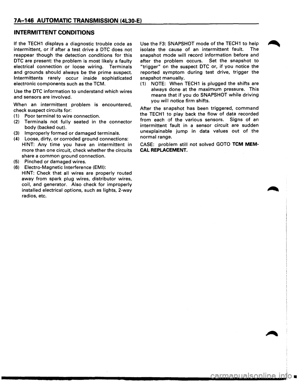
INTERMITTENT CONDITIONS
If the TECH1 displays a diagnostic trouble code as
intermittent, or if after a test drive a DTC does not
reappear though the detection conditions for this
DTC are present: the problem is most likely a faulty
electrical connection or loose wiring. Terminals
and
grounds should always be the prime suspect.
lntermittents rarely occur inside sophisticated
electronic components such
as the TCM.
Use the
DTC information to understand which wires
and sensors are involved.
When an
intermittent problem is encountered,
check suspect circuits for:
(1) Poor terminal to wire connection.
(2) Terminals not fully seated in the connector
body (backed out).
(3) Improperly formed or damaged terminals.
(4) Loose, dirty, or corroded ground connections:
HINT: Any time you have an intermittent in
more than one circuit, check whether the circuits
share a
common ground connection.
(5) Pinched or damaged wires.
(6) Electro-Magnetic Interference (EMI):
HINT:
Check that all wires are properly routed
away from spark plug wires, distributor wires,
coil, and generator. Also check
for improperly
installed electrical options, such as lights, 2-way
radios, etc. Use
the
F3: SNAPSHOT mode of the TECH 1 to help
isolate the cause
of an intermittent fault. The
snapshot
mode will record information before and
after the problem occurs. Set the snapshot
to
"trigger" on the suspect DTC or, if you notice the
reported
symptom during test drive, trigger the
snapshot
manually.
(1) NOTE: When TECH1 is plugged the shifts are
always
done at the maximum pressure. This
means
that if you do SNAPSHOT while driving
you will! notice firm shifts.
After the snapshot has been triggered, command
the TECH1 to play back the flow of data recorded
from each of the various sensors. Signs of an
intermittent fault in a sensor circuit are sudden
unexplainable jump in data values out of the
normal range.
CASE:
problem still not solved GOTO TCM MEM
CAL REPLACEMENT.
•
Page 1436 of 1928
8-246 CHASSIS ELECTRICAL
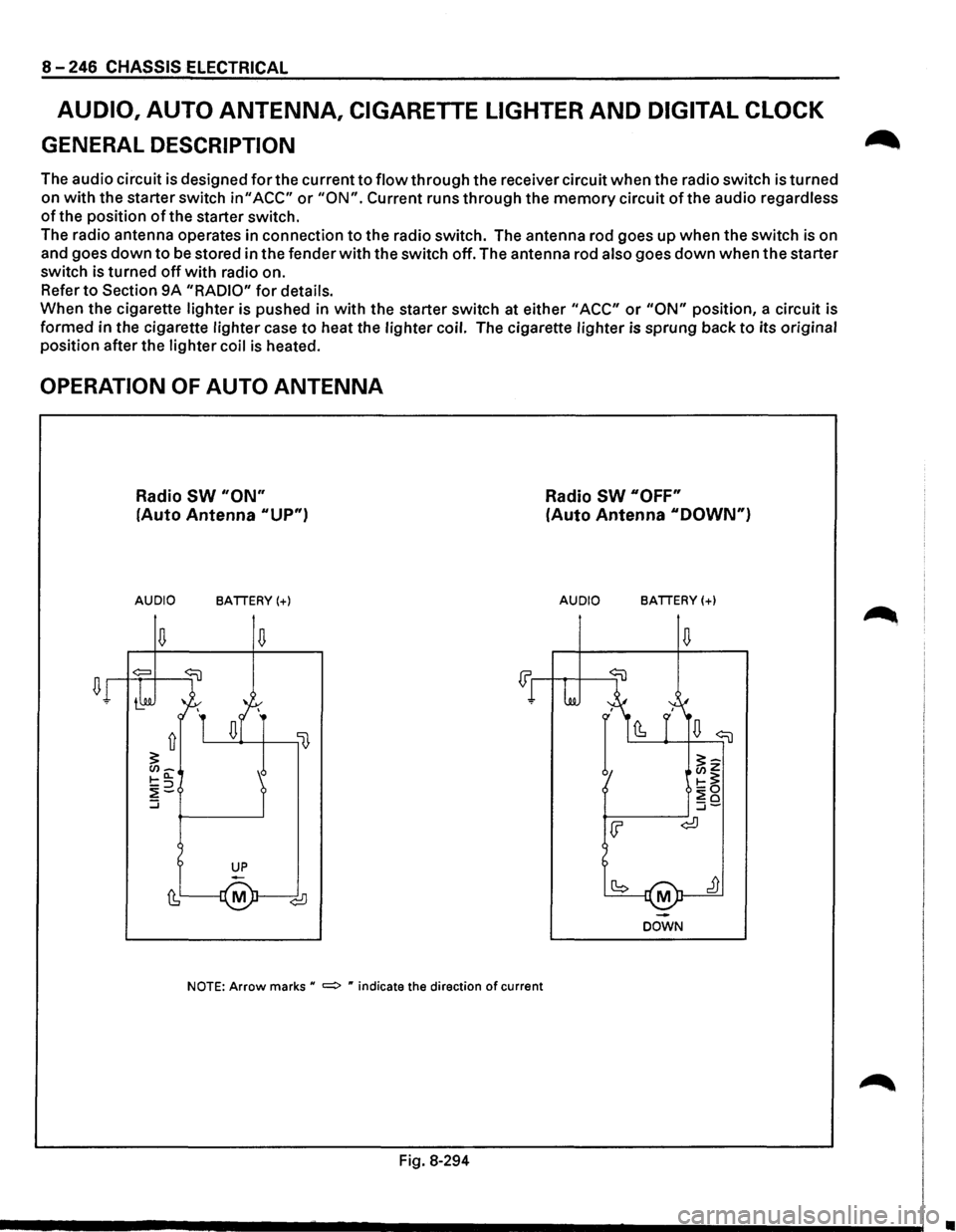
AUDIO, AUTO ANTENNA, CIGARETTE LIGHTER AND DIGITAL CLOCK
GENERAL DESCRIPTION
The audio circuit is designed for the current to flow through the receiver circuit when the radio switch is turned
on
with the starter switch in" ACC" or "ON". Current runs through the memory circuit of the audio regardless
of the position of the starter switch.
The radio antenna operates in connection
to the radio switch. The antenna rod goes up when the switch is on
and goes
down to be stored in the fender with the switch off. The antenna rod also goes down when the starter
switch is turned
off with radio on.
Refer
to Section 9A "RADIO" for details.
When the cigarette lighter is pushed in
with the starter switch at either "ACC" or "ON" position, a circuit is
formed in the cigarette lighter case
to heat the lighter coil. The cigarette lighter is sprung back to its original
position after the lighter coil
is heated.
OPERATION OF AUTO ANTENNA
Radio SW "ON"
(Auto Antenna "UP")
AUDIO BATTERY(+)
NOTE: Arrow marks u =:> " indicate the direction of current
Fig. 8-294
Radio SW "OFF"
(Auto Antenna "DOWN")
AUDIO BATTERY(+)
M
DOWN
•
Page 1441 of 1928
AUDIO
AUTO ANTENNA
Refer to Section 9A "RADIO" for details.
CIGARETTE LIGHTER
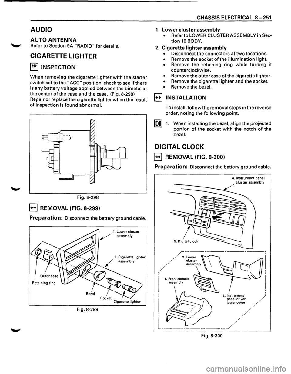
~ INSPECTION
When removing the cigarette lighter with the starter
switch set
to the "ACC" position, check to see if there
is any battery voltage applied between the bimetal at
the center
of the case and the case. (Fig. 8-298)
Repair
or replace the cigarette lighter when the result
of inspection is found abnormal.
Fig. 8-298
B REMOVAL (FIG. 8-299)
Preparation: Disconnect the battery ground cable.
Retaining ring
Fig. 8-299
CHASSIS ELECTRICAL 8-251
1. lower cluster assembly
• Refer to LOWER CLUSTER ASSEMBLY in Sec
tion 10 BODY.
2. Cigarette lighter assembly
• Disconnect the connectors at two locations.
• Remove the socket of the illumination light.
•
Remove the retaining ring while turning it
counterclockwise.
• Remove the outer case of the cigarette lighter.
• Remove the cigarette lighter and the socket.
• Remove the bezel.
I••! INSTALLATION
To install, follow the removal steps in the reverse
order, noting the
following point.
1. When installing the bezel, align the projected
portion
of the socket with the notch of the
bezel.
DIGITAL CLOCK
B REMOVAL (FIG. 8-300)
Preparation: Disconnect the battery ground cable.
Fig.
8-300
4. Instrument panel cluster assembly
Page 1577 of 1928
RADIO 9A-1
ACCESSORIES
Radio .................................................. .
Parts Location ..............................•...........
Circuit Diagram ......•.................................
Antenna ....•......................................•........
Auto Antenna ......................................... .
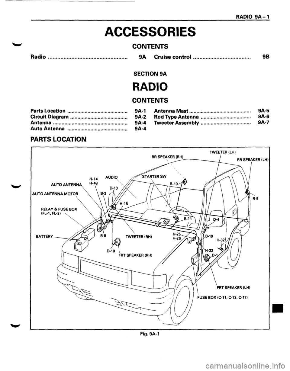
PARTS LOCATION
AUDIO
AUTO ANTENNA
AUTO ANTENNA MOTOR
CONTENTS
9A Cruise control ................................... ..
SECTION 9A
RADIO
CONTENTS
9A-1
9A-2
9A-4
9A-4 Antenna
Mast ........ ~ ................................. .
Rod Type Antenna .................................. .
Tweeter
Assembly .................................. .
lWEETER (LH)
98
9A-5
9A-6
9A·7
RR SPEAKER !RH) ----~ RR SPEAKER (lHl
BATTERY lWEETER (RH)
FRT SPEAKER (LHl
FUSE BOX (C-11, C-12, C-17)
Fig. 9A-1
•
Page 1578 of 1928
9A-2 RADIO
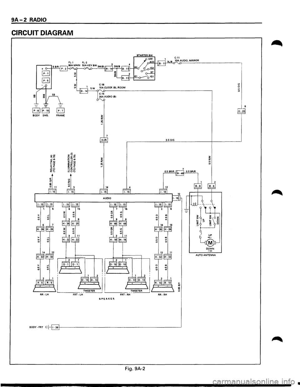
CIRCUIT DIAGRAM
~~P~1o[ B H · 26 BODY ENG. FRAME
H-25 0.5 0/G
~~ ~~~ ~ ~ :!ob ~==~«> <(w
SPEAKER
BODY-FAT II l-39r------------------------------------------------------------"
Fig. 9A-2
..
Page 1579 of 1928
![ISUZU TROOPER 1995 Workshop Manual CONNECTOR LIST
~
~
~ ~
Fig. 9A-3
1]1] lo-1ol
[E] IR-101
IH-32IIGRADESIIH-48I
RADIO 9A-3](/img/61/57183/w960_57183-1578.png "ISUZU TROOPER 1995 Workshop Manual CONNECTOR LIST
~
~
~ ~
Fig. 9A-3
1]1] lo-1ol
[E] IR-101
IH-32IIGRADESIIH-48I
RADIO 9A-3")
CONNECTOR LIST
~
~
~ ~
Fig. 9A-3
1]1] lo-1ol
[E] IR-101
IH-32IIGRADESIIH-48I
RADIO 9A-3
Page 1580 of 1928
9A-4 RADIO
ANTENNA
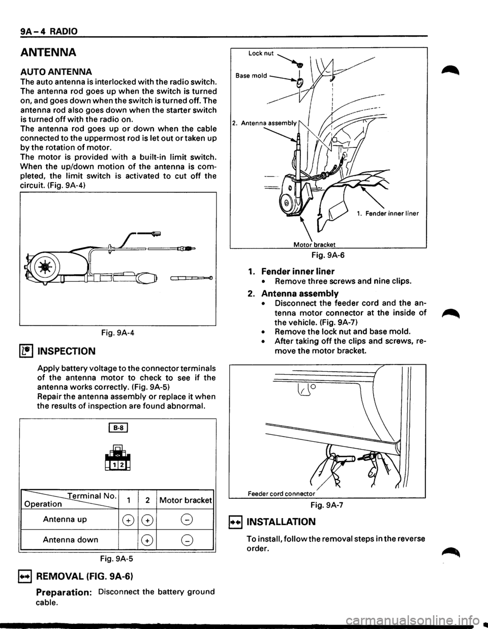
AUTO ANTENNA
The auto antenna is interlocked with the radio switch.
The antenna rod goes up when the switch is turned
on, and goes
down when the switch is turned off. The
antenna rod
also goes down when the starter switch
is turned
off with the radio on.
The antenna rod goes up
or down when the cable
connected to the uppermost rod is let out or taken up
by the rotation of motor.
The
motor is provided with a built-in limit switch.
When the up/down
motion of the antenna is com
pleted, the
limit switch is activated to cut off the
circuit. (Fig. 9A-4)
0
Fig. 9A-4
(1!] INSPECTION
Apply battery voltage to the connector terminals
of the antenna motor to check to see if the
antenna works correctly. (Fig. 9A-5)
Repair the antenna assembly
or replace it when
the results
of inspection are found abnormal.
[EJ
~
~0. Op 1 2 Motor bracket
Antenna up
G
Antenna down
Fig. 9A-5
B REMOVAL (FIG. 9A-6)
G G
G G
Preparation: Disconnect the battery ground
cable.
Locknut~
B"e mold --b I
___,
------------
1. Fender inner liner
Fig. 9A-6
1. Fender inner liner
• Remove three screws and nine clips.
2. Antenna assembly
• Disconnect the feeder cord and the an
tenna
motor connector at the inside of
the vehicle. (Fig. 9A-7)
• Remove the lock nut and base mold.
• After taking off the clips and screws, re
move the motor bracket.
lJO
Feeder cord connector
Fig. 9A-7
E) INSTALLATION
To install, follow the removal steps in the reverse
order.