ignition ISUZU TROOPER 1995 Workshop Manual
[x] Cancel search | Manufacturer: ISUZU, Model Year: 1995, Model line: TROOPER, Model: ISUZU TROOPER 1995Pages: 1928
Page 3 of 1928
•:1
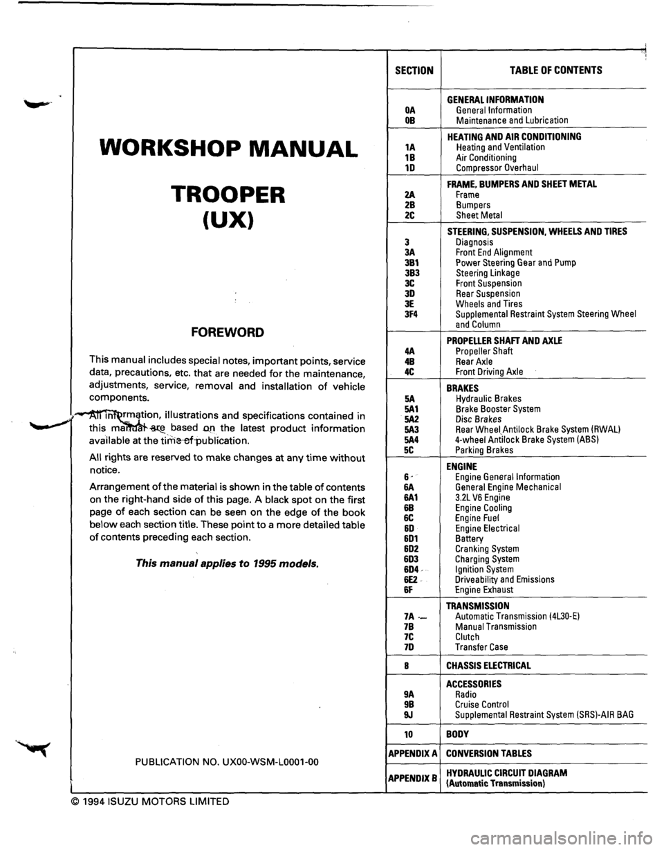
SECTION TABLE OF CONTENTS
. GENERAL INFORMATION OA General Information OB Maintenance and Lubrication
WORKSHOP MANUAL
HEATING AND AIR CONDITIONING 1A Heating and Ventilation
1B Air Conditioning 1D Compressor Overhaul
TROOPER
FRAME, BUMPERS AND SHEET METAL
2A Frame 2B Bumpers
(UX) 2C Sheet Metal
STEERING, SUSPENSION, WHEELS AND TIRES
3 Diagnosis 3A Front End Alignment 3B1 Power Steering Gear and Pump 3B3 Steering Linkage 3C Front Suspension 3D Rear Suspension 3E Wheels and Tires 3F4 Supplemental Restraint System Steering Wheel
FOREWORD and Column
PROPELLER SHAFT AND AXLE 4A Propeller Shaft This manual includes special notes, important points, service 4B Rear Axle
data, precautions, etc. that are needed for the maintenance, 4C Front Driving Axle
adjustments, service, removal and installation of vehicle BRAKES components. 5A Hydraulic Brakes
·~ m rmation, illustrations and specifications contained in 5A1 Brake Booster System
.. _,. 5A2 Disc Brakes ~ this ma. ~-based D.fl the latest product information 5A3 Rear Wheei_Antilock Brake System (RWAL)
available at the tirrHHrl·publication. 5A4 4-wheel Antilock Brake System (ABS)
5C Parking Brakes All rights are reserved to make changes at any time without ENGINE notice. 6· Engine General Information Arrangement of the material is shown in the table of contents &A General Engine Mechanical
on the right-hand side of this page. A black spot on the first 6A1 3.2L VB Engine
page of each section can be seen on the edge of the book &B Engine Cooling
6C Engine Fuel below each section title. These point to a more detailed table &D Engine Electrical of contents preceding each section. 6D1 Battery 6D2 Cranking System
This manual applies to 1995 models. 6D3 Charging System 6D4-Ignition System 6E2. Driveability and Emissions 6F Engine Exhaust
TRANSMISSION 7A-Automatic Transmission (4L30·E) 7B Manual Transmission 7C Clutch 7D Transfer Case
8 CHASSIS ELECTRICAL
ACCESSORIES 9A Radio 9B Cruise Control 9J Supplemental Restraint System (SRS)-AIR BAG
10 BODY
APPENDIX A CONVERSION TABLES PUBLICATION NO. UXOO-WSM-L0001-00
APPENDIXB HYDRAULIC CIRCUIT DIAGRAM (Automatic Transmission)
© 1994 ISUZU MOTORS LIMITED
Page 14 of 1928
OA-10 GENERAL INFORMATION
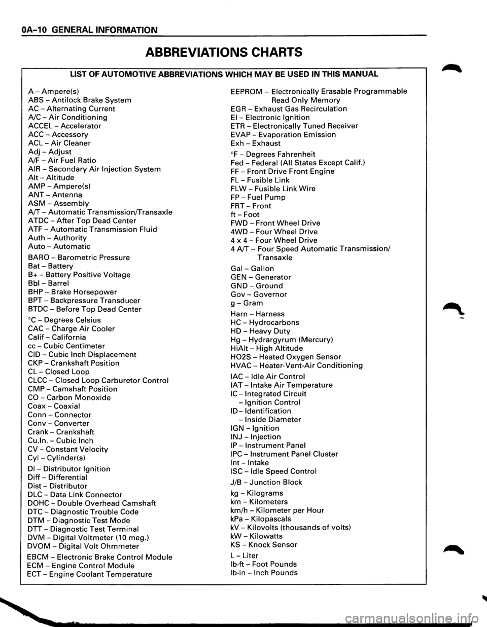
ABBREVIATIONS CHARTS
LIST OF AUTOMOTIVE ABBREVIATIONS WHICH MAY BE USED IN THIS MANUAL
A-Ampere(s)
ABS-Anti lock Brake System
AC-Alternating Current
A/C-Air Conditioning
ACCEL-Accelerator
ACC-Accessory
ACL-Air Cleaner
Adj-Adjust
A/F-Air Fuel Ratio
AIR-Secondary Air Injection System
Alt-Altitude
AMP-Ampere(s)
ANT-Antenna
ASM-Assembly
A/T-Automatic Transmission/Transaxle
ATDC-After Top Dead Center
ATF-Automatic Transmission Fluid
Auth -Authority
Auto -Automatic
BARO-Barometric Pressure
Bat -Battery
B+-Battery Positive Voltage
Bbl-Barrel
BHP-Brake Horsepower
BPT-Backpressure Transducer
BTDC-Before Top Dead Center
oc-Degrees Celsius
CAC-Charge Air Cooler
Calif-California
cc-Cubic Centimeter
CID-Cubic Inch Displacement
CKP-Crankshaft Position
CL-Closed Loop
CLCC-Closed Loop Carburetor Control
CMP-Camshaft Position
CO-Carbon Monoxide
Coax-Coaxial
Conn-Connector
Conv -Converter
Crank-Crankshaft
Cu.ln.-Cubic Inch
CV-Constant Velocity
Cyl-Cylinder(s)
Dl -Distributor Ignition
Diff-Differential
Dist-Distributor
DLC-Data Link Connector
DOHC-Double Overhead Camshaft
DTC-Diagnostic Trouble Code
DTM-Diagnostic Test Mode
DTT-Diagnostic Test Terminal
DVM-Digital Voltmeter (10 meg.)
DVOM-Digital Volt Ohmmeter
EBCM-Electronic Brake Control Module
ECM-Engine Control Module
ECT-Engine Coolant Temperature
EEPROM -Electronically Erasable Programmable
Read Only Memory
EGR-Exhaust Gas Recirculation
El-Electronic Ignition
ETR-Electronically Tuned Receiver
EVAP-Evaporation Emission
Exh-Exhaust
°F-Degrees Fahrenheit
Fed -
Federal (All States Except Calif.)
FF-Front Drive Front Engine
FL-Fusible Link
FLW-Fusible Link Wire
FP-Fuel Pump
FRT-Front
ft-Foot
FWD-Front Wheel Drive
4WD-Four Wheel Drive
4 x
4-Four Wheel Drive
4 A/T-Four Speed Automatic Transmission/
Transaxle
Gal-Gallon
GEN-Generator
GND-Ground
Gov-Governor
g-Gram
Harn -Harness
HC-Hydrocarbons
HD-Heavy Duty
Hg-Hydrargyrum (Mercury)
HiAit-High Altitude
H02S - Heated Oxygen Sensor
HVAC-Heater-Vent-Air Conditioning
lAC-Idle Air Control
IAT -Intake Air Temperature
IC-Integrated Circuit
-
Ignition Control
ID-Identification
-Inside Diameter
IGN-Ignition
INJ-Injection
IP-Instrument Panel
IPC-Instrument Panel Cluster
lnt-Intake
ISC-Idle Speed Control
J/B-Junction Block
kg -Kilograms
km-Kilometers
km/h -Kilometer per Hour
kPa-Kilopascals
kV-Kilovolts (thousands of volts)
kW-Kilowatts
KS -Knock Sensor
L-Liter
lb·ft-Foot Pounds
lb·in-Inch Pounds
Page 38 of 1928
1A-8 HEATING AND VENTILATION
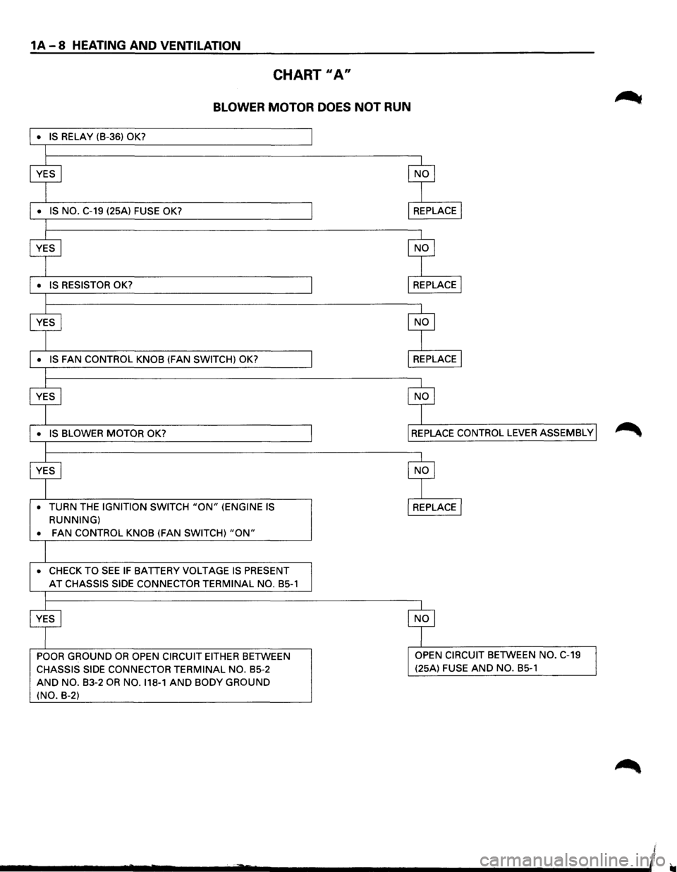
CHART II A"
BLOWER MOTOR DOES NOT RUN
• TURN THE IGNITION SWITCH "ON" (ENGINE IS
RUNNING)
•
FAN CONTROL KNOB (FAN SWITCH) "ON"
• CHECK TO SEE IF BATTERY VOLTAGE IS PRESENT
AT CHASSIS SIDE CONNECTOR TERMINAL NO. B5-1
POOR GROUND OR OPEN CIRCUIT EITHER BETWEEN
CHASSIS SIDE CONNECTOR TERMINAL NO. B5-2
AND NO. B3-2 OR NO. 118-1 AND BODY GROUND
(NO. B-2) (25A)
FUSE AND NO. B5-1
Page 69 of 1928
AIR CONDITIONING 1 B -15
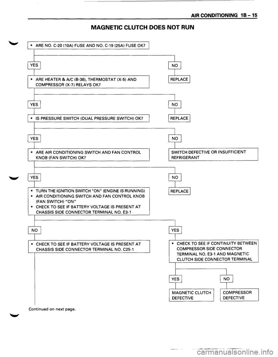
MAGNETIC CLUTCH DOES NOT RUN
• ARE NO. C-20 (10A) FUSE AND NO. C-19 (25A) FUSE OK?
•
ARE HEATER & A!C (B-36), THERMOSTAT (X-5) AND
COMPRESSOR (X-7) RELAYS OK?
•
ARE AIR CONDITIONING SWITCH AND FAN CONTROL
KNOB
(FAN SWITCH) OK?
•
TURN THE IGNITION SWITCH "ON" (ENGINE IS RUNNING)
• AIR CONDITIONING SWITCH
AND FAN CONTROL KNOB
(FAN SWITCH) "ON"
• CHECK TO SEE IF BATTERY VOLTAGE IS PRESENT AT
CHASSIS SIDE CONNECTOR TERMINAL NO. E3-1
• CHECK TO SEE IF BATTERY VOLTAGE IS PRESENT AT
CHASSIS SIDE CONNECTOR TERMINAL NO. C25-1
Continued on next page.
SWITCH DEFECTIVE OR INSUFFICIENT
REFRIGERANT
• CHECK TO
SEE IF CONTINUITY BETWEEN
COMPRESSOR SIDE CONNECTOR
TERMINAL NO.
E3-1 AND MAGNETIC
CLUTCH SIDE CONNECTOR TERMINAL
Page 127 of 1928
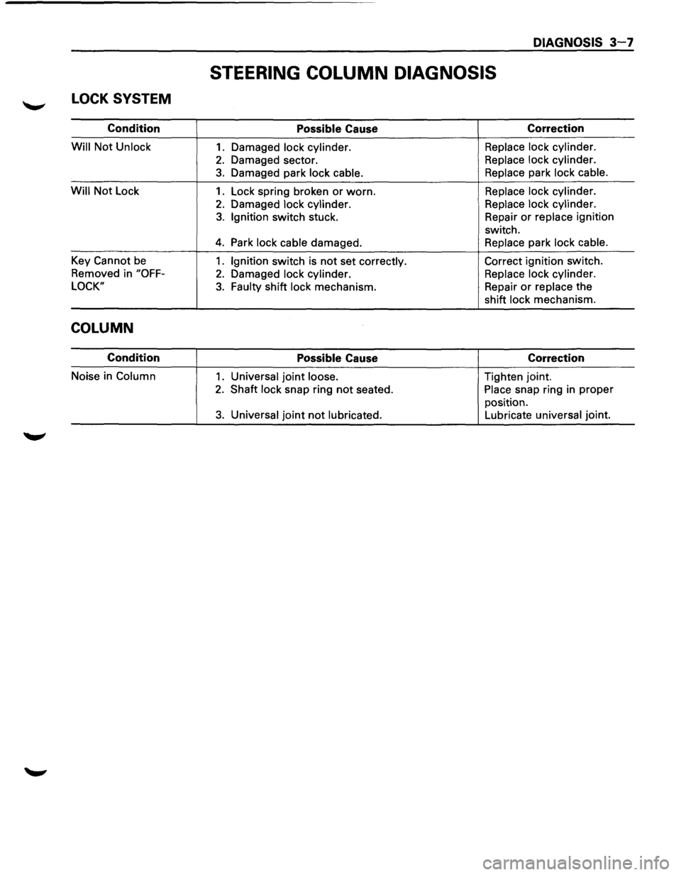
LOCK SYSTEM
Condition
Will Not Unlock
Will Not Lock
Key
Cannot be
Removed in "OFF-
LOCK"
COLUMN
Condition
Noise in Column
DIAGNOSIS 3-7
STEERING COLUMN DIAGNOSIS
Possible Cause
1. Damaged lock cylinder.
2. Damaged sector.
3. Damaged park lock cable.
1. Lock spring broken or worn.
2. Damaged lock cylinder.
3. Ignition switch stuck.
4. Park lock cable damaged.
1. Ignition switch is not set correctly.
2. Damaged lock cylinder.
3. Faulty shift lock mechanism.
Possible Cause
1. Universal joint loose.
2. Shaft lock snap ring not seated.
3. Universal joint not lubricated.
Correction
Replace lock cylinder.
Replace lock cylinder.
Replace park lock cable.
Replace lock cylinder.
Replace lock cylinder.
Repair
or replace ignition
switch.
Replace park lock cable.
Correct ignition switch.
Replace lock cylinder.
Repair
or replace the
shift lock mechanism.
Correction
Tighten joint.
Place snap ring in proper
position.
Lubricate universal joint.
Page 211 of 1928
SUPPLEMENTAL RESTRAINT SYSTEM (SRSl STEERING WHEEL & COLUMN 3F4-1
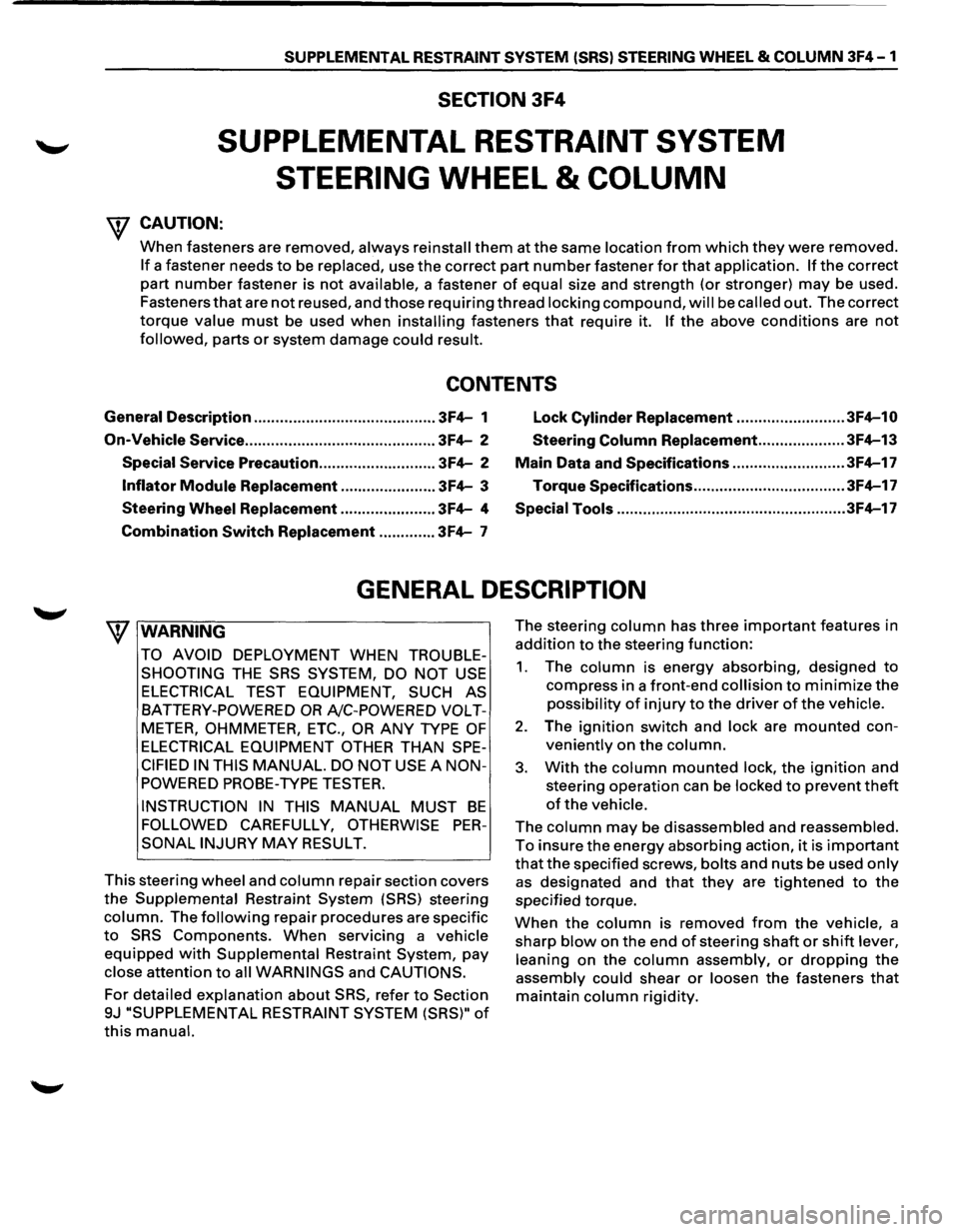
SECTION 3F4
SUPPLEMENTAL RESTRAINT SYSTEM
STEERING
WHEEL & COLUMN
W CAUTION:
When fasteners are removed, always reinstall them at the same location from which they were removed.
If a fastener needs to be replaced, use the correct part number fastener for that application. If the correct
part
number fastener is not available, a fastener of equal size and strength (or stronger) may be used.
Fasteners
that are not reused, and those requiring thread locking compound, will be called out. The correct
torque value must be used when installing fasteners that require it. If the above conditions are not
followed, parts or system damage could result.
CONTENTS
General Description .......................................... 3F4-1
Lock Cylinder Replacement ......................... 3F4-10
On-Vehicle Service
............................................ 3F4-2 Steering Column Replacement .................... 3F4-13
Special Service Precaution ........................... 3F4-2 Main Data and Specifications .......................... 3F4-17
Inflator Module Replacement ...................... 3F4-3 Torque
Specifications ................................... 3F4-17
Steering Wheel Replacement ...................... 3F4-4 Special Tools ..................................................... 3F4-17
Combination
Switch Replacement ............. 3F4-7
GENERAL DESCRIPTION
W WARNING
TO AVOID DEPLOYMENT WHEN TROUBLE
SHOOTING
THE SRS SYSTEM, DO NOT USE
ELECTRICAL TEST EQUIPMENT, SUCH AS
BATTERY-POWERED OR A/C-POWERED VOLT
METER, OHMMETER, ETC., OR ANY TYPE OF
ELECTRICAL EQUIPMENT OTHER THAN SPE
CIFIED IN THIS MANUAL. DO NOT USE A NON
POWERED
PROBE-TYPE TESTER.
INSTRUCTION IN THIS MANUAL MUST BE
FOLLOWED CAREFULLY, OTHERWISE PER
SONAL INJURY MAY RESULT.
This steering
wheel and column repair section covers
the Supplemental Restraint System (SRS) steering
column. The following repair procedures are specific
to SRS Components. When servicing a vehicle
equipped with Supplemental Restraint System, pay
close attention to all WARNINGS and CAUTIONS.
For detailed explanation about SRS, refer to Section
9J "SUPPLEMENTAL
RESTRAINT SYSTEM (SRS)" of
this manual.
The steering column has three important features in
addition to the steering function:
1. The column is energy absorbing, designed to
compress in a front-end collision to minimize the
possibility of injury to the driver of the vehicle.
2. The ignition switch and lock are mounted con
veniently on the column.
3. With the column mounted lock, the ignition and
steering operation can be
locked to prevent theft
of the vehicle.
The column may be disassembled and reassembled.
To insure the energy absorbing action, it is important
that the specified screws, bolts and nuts be used only
as designated and that they are tightened to the
specified torque.
When the column is removed from the vehicle, a
sharp
blow on the end of steering shaft or shift lever,
leaning
on the column assembly, or dropping the
assembly could shear or loosen the fasteners that
maintain column rigidity.
Page 213 of 1928
SUPPLEMENTAL RESTRAINT SYSTEM (SRS) STEERING WHEEL & COLUMN 3F4-3
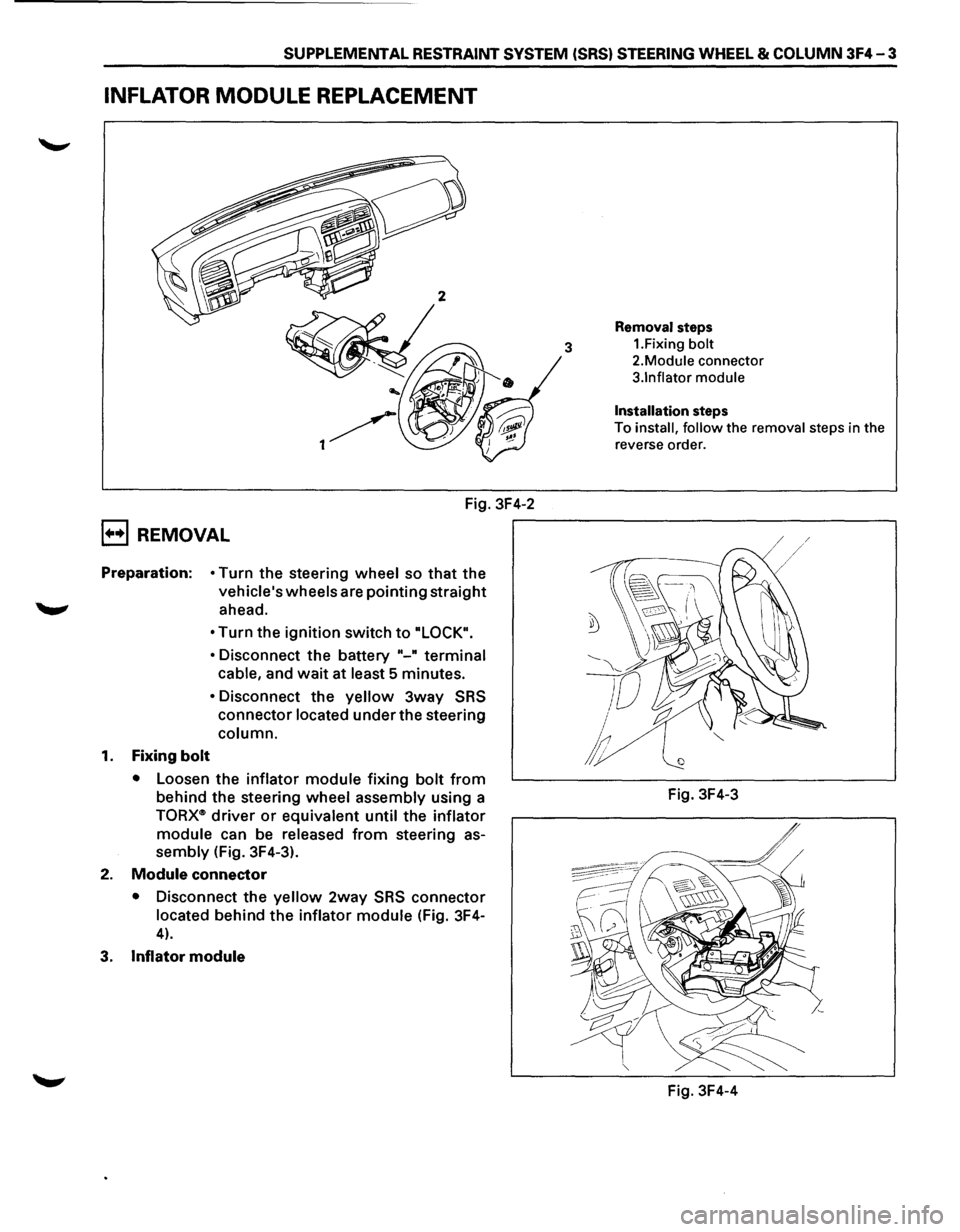
INFLATOR MODULE REPLACEMENT
Fig. 3F4-2
B REMOVAL
Preparation: • Turn the steering wheel so that the
vehicle's wheels are pointing straight
._,. ahead.
1. Fixing bolt
• Turn the ignition switch to "LOCK".
•
Disconnect the battery "-" terminal
cable,
and wait at least 5 minutes.
• Disconnect the yellow 3way SRS
connector located under the steering
column.
•
Loosen the inflator module fixing bolt from
behind the steering wheel assembly using a
TORX<~> driver or equivalent until the inflator
module
can be released from steering as
sembly (Fig. 3F4-3).
2. Module connector
• Disconnect the yellow 2way SRS connector
located behind the inflator module (Fig. 3F4-
4).
3. Inflator module
Removal steps
3 1.Fixing bolt
2.Module connector
3.1nflator module
Installation steps
To install, follow the removal steps in the
reverse order.
Fig. 3F4-3
Fig. 3F4-4
Page 214 of 1928
![ISUZU TROOPER 1995 Workshop Manual 3F4-4 SUPPLEMENTAL RESTRAINT SYSTEM (SRS) STEERING WHEEL & COLUMN
(b!] INSPECTION AND REPAIR
\f WARNING
THE INFLATOR MODULE SHOULD ALWAYS BE
CARRIED WITH THE URETHANE COVER AWAY
FROM YOUR BODY](/img/61/57183/w960_57183-213.png "ISUZU TROOPER 1995 Workshop Manual 3F4-4 SUPPLEMENTAL RESTRAINT SYSTEM (SRS) STEERING WHEEL & COLUMN
(b!] INSPECTION AND REPAIR
\f WARNING
THE INFLATOR MODULE SHOULD ALWAYS BE
CARRIED WITH THE URETHANE COVER AWAY
FROM YOUR BODY")
3F4-4 SUPPLEMENTAL RESTRAINT SYSTEM (SRS) STEERING WHEEL & COLUMN
(b!] INSPECTION AND REPAIR
\f' WARNING
THE INFLATOR MODULE SHOULD ALWAYS BE
CARRIED WITH THE URETHANE COVER AWAY
FROM YOUR BODY AND SHOULD ALWAYS BE
LAID ON A FLAT SURFACE WITH THE URE
THANE SIDE UP. THIS IS NECESSARY BE
CAUSE A FREE SPACE IS PROVIDED TO ALLOW
THE AIR CUSHION TO EXPAND IN THE UN
LIKELYEVENT OF ACCIDENTAL DEPLOYMENT.
OTHERWISE, PERSONAL INJURY
MAY RESULT
(FIG. 3F4-5).
Fig. 3F4-5
The
Inflator module consists of a cover, air bag,
inflator, and retainer.
Inspect the Inflator module
mainly for the following:
1) Check for holes, cracks, severe blemishes and
deformation on the cover.
2) Check that the retainer is not deformed.
3) Check for defects such as damage and breakage in
the lead
wire ofthe squib.
If an abnormality is found as the result of the in
spection, replace the
Inflator module with a new one.
l·u·IINSTALLATION
3. Inflator module
2. Module connector
• Support the module and carefully connectthe
module connector.
NOTE:
Pass the lead wire through the tabs on the plastic
cover (wire protector)
of inflator to prevent lead
wire
from being pinched.
1. Fixing bolt
• Secure the module with one bolt to relieve
weight on the connector wire.
• Tighten bolts to specified sequence as figure
(Fig. 3F4-6).
Torque
N·m(lb·in.) 8 (69)
• Connect the yellow 3way SRS connector
located under the steering column.
• Connect the battery .. _. terminal cable.
• Set ignition to "ON" while watching warning light.
Light should flash 7 times and then go off.
If lamp
does
not operate correctly, refer to Section 9J.
Fig. 3F4-6
STEERING WHEEL REPLACEMENT
\f' CAUTION:
Once the steering column is removed from the
vehicle, the
column is extremely susceptible to
damage. Dropping the column assembly on its
end
could collapse the steering shaft or loosen
the
slide block which maintains column rigidity.
Leaning on the column assembly could cause the
jacket
to bend or deform. Any of the above
damage could
impair the column's collapsible
design. If it is necessary to remove the steering
wheel, use
only the specified steering wheel
puller.
Under no conditions should the end of the
shaft be hammered upon,
as hammering could
loosen
slide block which maintains column
rigidity.
•
Page 215 of 1928
SUPPLEMENTAL RESTRAINT SYSTEM (SRS) STEERING WHEEL & COLUMN 3F4-5
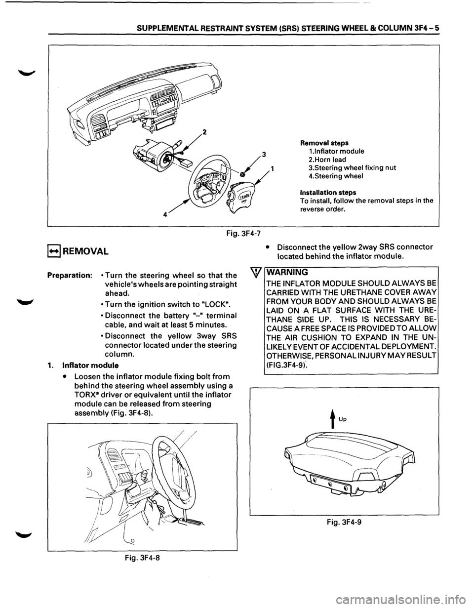
Removal steps
1.1nflator module
2.Horn lead
1 3.Steering wheel fixing nut
4.Steering wheel
Installation steps
To
install, follow the removal steps in the
reverse order.
Fig. 3F4-7
E) REMOVAL
Preparation: • Turn the steering wheel so that the
vehicle's wheels are
pointing straight
ahead.
• Turn the ignition switch to "LOCK".
•
Disconnect the battery "-• terminal
cable, and
wait at least 5 minutes.
• Disconnect the yellow 3way SRS
connector located under the steering
column.
1. Inflator module
• Loosen the inflator module fixing bolt from
behind the steering wheel assembly using a
TORXe driver or equivalent until the inflator
module can be released from steering
assembly (Fig. 3F4-8).
Fig. 3F4-8
• Disconnect the yellow 2way SRS connector
located behind
the inflator module.
W WARNING
THE INFLATOR MODULE SHOULD ALWAYS BE
CARRIED WITH THE URETHANE COVER AWAY
FROM YOUR BODY AND SHOULD ALWAYS BE
LAID ON A FLAT SURFACE WITH THE URE
THANE SIDE UP. THIS IS NECESSARY BE
CAUSE A FREE SPACE IS PROVIDED TO ALLOW
THE AIR CUSHION TO EXPAND IN THE UN
LIKELY EVENT
OF ACCIDENTAL DEPLOYMENT.
OTHERWISE, PERSONAL INJURY MAY RESULT
(FIG.3F4-9l".
Fig. 3F4-9
Page 216 of 1928
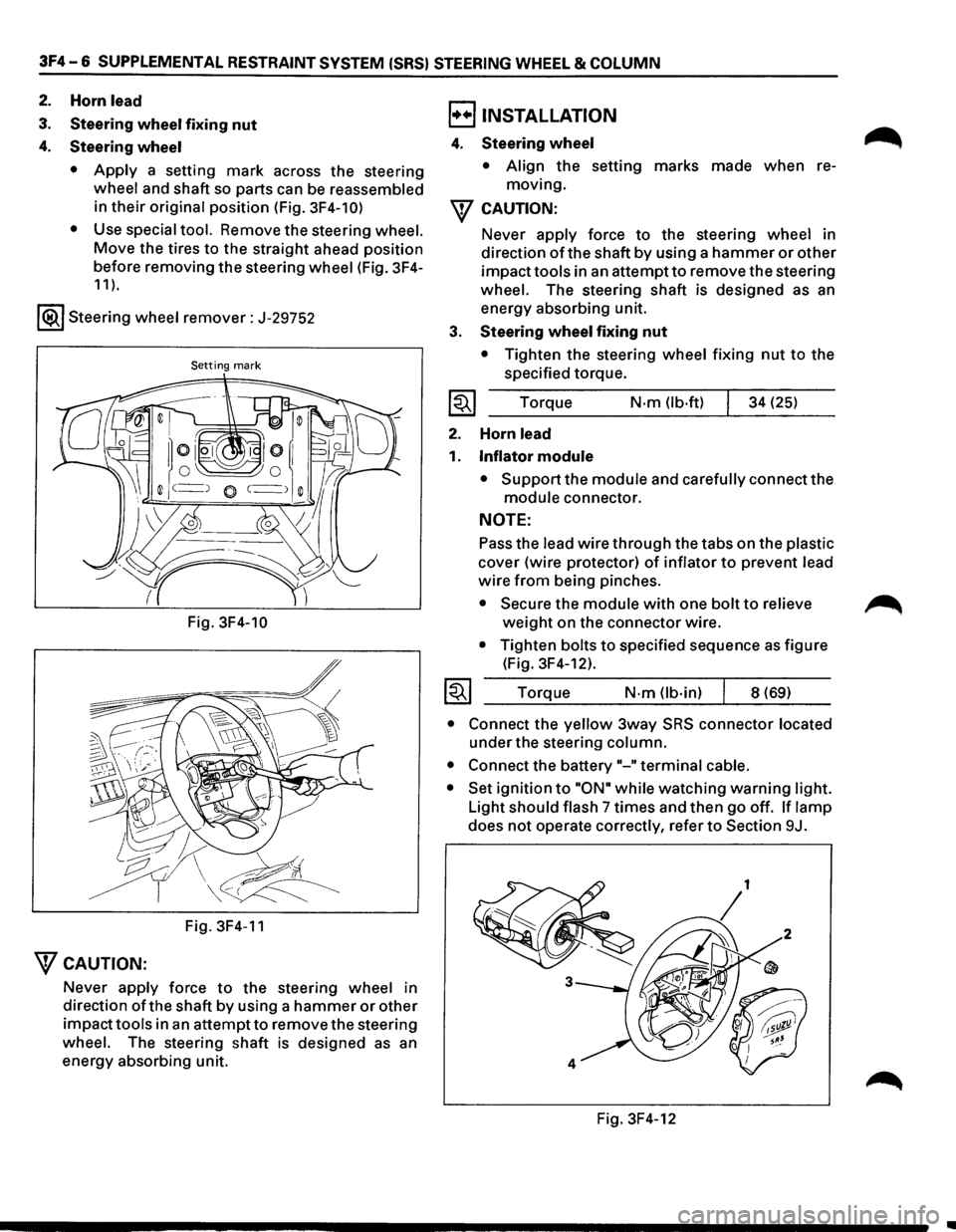
3F4-6 SUPPLEMENTAL RESTRAINT SYSTEM ISRSI STEERING WHEEL & COLUMN
2. Horn lead
3. Steering wheel fixing nut
4. Steering wheel
• Apply a setting mark across the steering
wheel and shaft so parts can be reassembled
in
their original position (Fig. 3F4-10)
•
Use special tool. Remove the steering wheel.
Move the tires to the straight ahead position
before removing
the steering wheel (Fig. 3F4-
11 ).
1®.1 Steering wheel remover: J-29752
Setting mark
Fig. 3F4-10
Fig. 3F4-11
"fCAUTION:
Never apply force to the steering wheel in
direction
ofthe shaft by using a hammer or other
impacttools in an attemptto remove the steering
wheel. The steering shaft is designed as an
energy absorbing unit.
B INSTALLATION
4. Steering wheel
• Align the setting marks made when re
moving.
"f CAUTION:
3.
~
2.
1.
~
Never apply force to the steering wheel in
direction
of the shaft by using a hammer or other
impacttools in an attemptto remove the steering
wheel. The steering shaft is designed as an
energy absorbing unit.
Steering wheel fixing nut
• Tighten the steering wheel fixing nut to the
specified torque.
Torque
N-m (lb·ft) 34 (25)
Horn
lead
Inflator module
• Support the module and carefully connect the
module connector.
NOTE:
Pass the lead wire through the tabs on the plastic
cover (wire protector) of inflator to prevent lead
wire from being pinches.
• Secure the module with one bolt to relieve
weight on the connector wire.
• Tighten bolts to specified sequence as figure
(Fig. 3F4-12).
Torque
N·m (lb-in) 8 (69)
• Connect the yellow 3way SRS connector located
under the steering column.
• Connect the battery"-" terminal cable.
• Set ignition to "ON• while watching warning light.
Light
should flash 7 times and then go off. If lamp
does not operate correctly, refer to Section 9J.
Fig. 3F4-12
~
•