air conditioning ISUZU TROOPER 1995 Owners Manual
[x] Cancel search | Manufacturer: ISUZU, Model Year: 1995, Model line: TROOPER, Model: ISUZU TROOPER 1995Pages: 1928
Page 858 of 1928
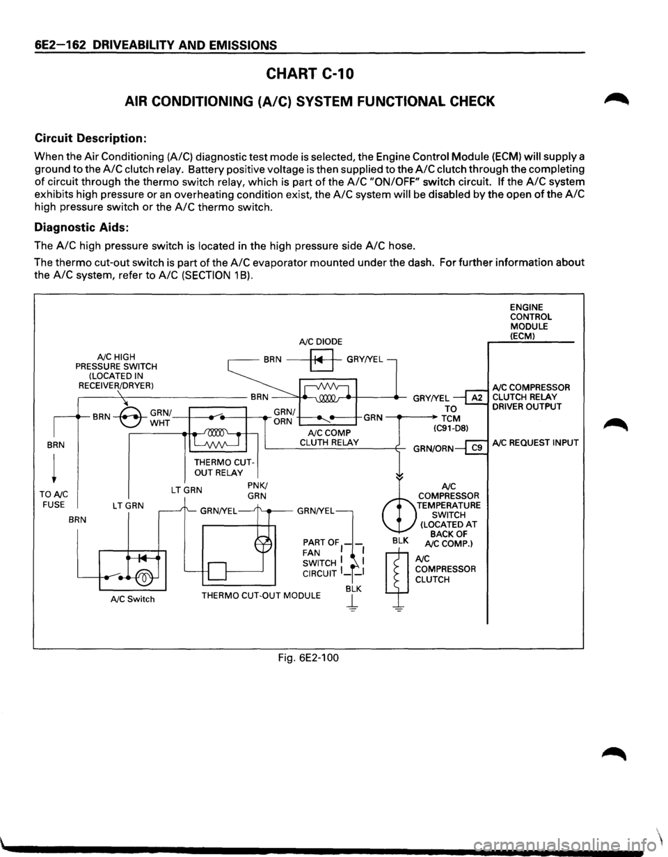
6E2-162 DRIVEABILITY AND EMISSIONS
CHART C-10
AIR CONDITIONING (A/C) SYSTEM FUNCTIONAL CHECK
Circuit Description:
When the Air Conditioning (A/C) diagnostic test mode is selected, the Engine Control Module (ECM) will supply a
ground to the
A/C clutch relay. Battery positive voltage is then supplied to the A/C clutch through the completing
of circuit through the thermo switch relay, which is part of the A/C "ON/OFF" switch circuit. If the A/C system
exhibits high pressure or
an overheating condition exist, the A/C system will be disabled by the open of the A/C
high pressure switch or the A/C thermo switch.
Diagnostic Aids:
The A/C high pressure switch is located in the high pressure side A/C hose.
The
thermo cut-out switch is part of the A/C evaporator mounted under the dash. For further information about
the
A/C system, refer to A/C (SECTION 1 8).
BRN
TONC FUSE
NC HIGH
PRESSURE SWITCH
(LOCATED IN
RECEIVER/DRYER)
LTGRN
BRN
NC Switch
NC DIODE
BRN a GRY!YEL
THERMO CUTOUT RELAY
LTGRN PNK/ GRN
NCCOMP CLUTH RELAY
PARTOF1-FAN I SWITCH I I CIRCUIT I __ I
BLK THERMO CUT-OUT MODULE j_
Fig. 6E2-100
ENGINE
CONTROL
MODULE (ECM)
NC COMPRESSOR CLUTCH RELAY DRIVER OUTPUT
NC REQUEST INPUT
Page 859 of 1928
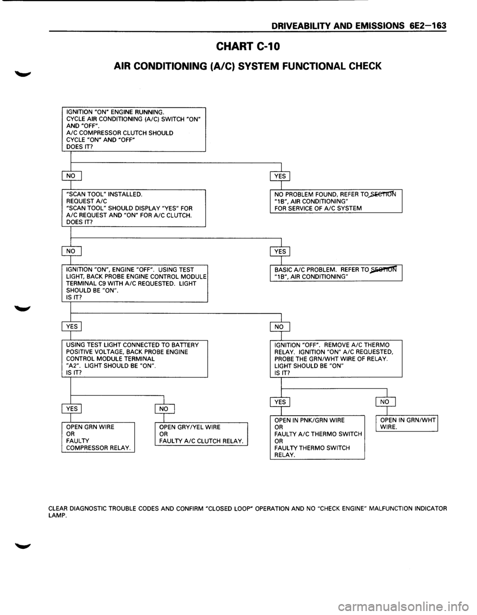
DRIVEABILITV AND EMISSIONS 6E2-163
CHART C-10
AIR CONDITIONING (A/C) SYSTEM FUNCTIONAL CHECK
IGNITION "ON" ENGINE RUNNING.
CYCLE AIR CONDITIONING (A/C) SWITCH "ON" AND "OFF". A/C COMPRESSOR CLUTCH SHOULD
CYCLE "ON" AND "OFF"
DOES IT?
$
$
"SCAN TOOL" INSTALLED.
NO PROBLEM FOUND, REFER TO)>e€TIO'N REQUEST A/C "1B", AIR CONDITIONING"
"SCAN TOOL" SHOULD DISPLAY "YES" FOR FOR SERVICE OF A/C SYSTEM A/C REQUEST AND "ON" FOR A/C CLUTCH.
DOES IT?
$
$
IGNITION "ON", ENGINE "OFF". USING TEST BASIC A/C PROBLEM. REFER TO~ LIGHT, BACK PROBE ENGINE CONTROL MODULE "1B", AIR CONDITIONING"
TERMINAL C9 WITH A/C REQUESTED. LIGHT
SHOULD BE "ON". IS IT?
$ $
USING TEST LIGHT CONNECTED TO BATTERY IGNITION "OFF". REMOVE A/C THERMO
POSITIVE VOLTAGE, BACK PROBE ENGINE RELAY. IGNITION "ON" A/C REQUESTED, CONTROL MODULE TERMINAL PROBE THE GRN/WHT WIRE OF RELAY. "A2". LIGHT SHOULD BE "ON". LIGHT SHOULD BE "ON" IS IT?
IS IT?
I
$ $
~ $ OPEN IN PNK/GRN WIRE I OPEN IN GRN/WHTJ OPEN GRN WIRE
OPEN GRY/YEL WIRE OR WIRE. OR OR FAULTY A/C THERMO SWITCH FAULTY FAULTY A/C CLUTCH RELAY. OR COMPRESSOR RELAY. FAULTY THERMO SWITCH RELAY.
CLEAR DIAGNOSTIC TROUBLE CODES AND CONFIRM "CLOSED LOOP" OPERATION AND NO "CHECK ENGINE" MALFUNCTION INDICATOR LAMP.
Page 876 of 1928
•
"'Tl c3' -..J )> I "'
~ )
DASH
BOARD
DISPLA
V
*
*
*
*
ATF
WARNING
LAMP
CHECK
TRANS
LAMP
POWER DRIVE MODE LAMP WINTER DRIVE MODE LAMP
~----------------
SHIFT INDICATOR
LAMP
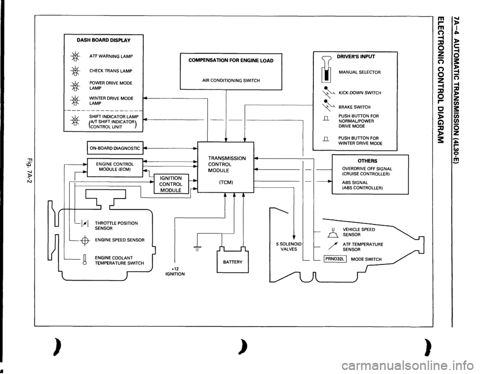
COMPENSATION
FOR
ENGINE
LOAD
AIR CONDITIONING SWITCH
TI
DRIVER'S
INPUT
liJ
MANUAL
SELECTOR
~
KICK-DOWN SWITCH
" ~
BRAKE
SWITCH
*
(AfT
SHIFT INDICATOR)
CONTROL
UNIT
---
' ---
I-------------,
il
PUSH BUTTON
FOR
NORMALJPOWER
DRIVE MODE
ON-BOARD DIAGNOSTIC
j4
.. ,
..
l__l--1 L_-$-L_g
ENGINE CONTROL
MODULE
(ECM)
_ IGNITION
CONTROL
I
MODULE
i
THROTTLE POSITION
SENSOR
ENGINE SPEED SENSOR
l
I
I -
ENGINE COOLANT TEMPERATU~,_.TCH
)
I +12 IGNITION
• •
TRANSMISSION
CONTROL MODULE
(TCM)
j
L I
BATTERY
)
--
~
'
5SOLENOID VALVES
il
-·----·
___.
u
PUSH BUTTON
FOR
WINTER DRIVE MODE
OTHERS
OVERDRIVE
OFF
SIGNAL
(CRUISE CONTROLLER)
ABS
SIGNAL
(ABS CONTROLLER)
f.-
n_
VEHICLE SPEED
SENSOR
f-
/
ATF TEMPERATURE SENSOR
L__ L__
[PRNDJ2L
I MODE SWITCH
-
m
.....
r-
)>
m
I
(")
..;=...
-t
)>
;::g 0
c:
2
-1
-
0
(")
s:
(")
~
0
-
2
n
-t
-1
;::g
:a
0
)> z
r-
en
c
s:
:;
(i)
C)
en
~
0 z
3:
-..;=... r-w 0 I !!!
)
Page 878 of 1928
7A-6 AUTOMATIC TRANSMISSION (4L30-E)
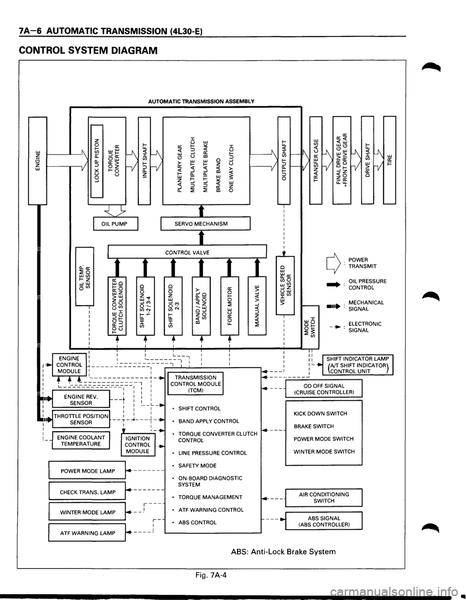
CONTROL SYSTEM DIAGRAM
L1J ~ (!) z L1J
I
I
lr
t:··
~ .. I I
I
I
AUTOMATIC TRANSMISSION ASSEMBLY
O.:a: :Eo LLJ(J) t-z --' L1J oVl
ENGINE COOLANT TEMPERATURE
ffio ~---a:O wz >LLJ z--' oo uCJ> w::C :::>u at-a:=> ~d
0 0 z ... w, --'"' o-.. (J)N t-.!-u.. J: CJ)
IGNITION
CONTROL .
MODULE
~==PO=W==ER==M=O=D=E=L=A=M=P~r.-------
r-------CHECK TRANS. LAMP
~=W=IN=T=E=R=M=O=D=E=LA=M=P~~--J---
::c u L1J a: 1-:.:: ::c <( :::> <( u L1J --' a: 1-(!) u al :::> >-L1J L1J 0 --' 1-~ z u a: :5 <( ~ ~ --' al Cl.
Cl. L1J i=
i= L1J ~ z :.:: --' --' <( L1J :5 :::> :::> a: z Cl. ::!: ::!: al 0
0 a: L1J 0 >-0 > --'o --' z (l._ 1-<( L1J Cl.Q 0 > __,...,
SHIFT
CONTROL
BAND APPLY CONTROL
TORQUE CONVERTER CLUTCH CONTROL
LINE PRESSURE CONTROL
SAFETY MODE
ON-BOARD DIAGNOSTIC
SYSTEM
TORQUE MANAGEMENT
ATF WARNING CONTROL
r-ABS CONTROL
L--A-T_F_w_A_R_N_I_N_G_L_A_M_P_...Jr---_l 1---------------'
0 L1J "'a: Bio wVl __,z uw J:Vl L1J >
POWER c): TRANSMIT
.... : OIL PRESSURE
CONTROL
MECHANICAL
...• : SIGNAL
LLJJ: ou ELECTRONIC ot:: -•: ::!:~ SIGNAL
KICK DOWN SWITCH
BRAKE SWITCH
POWER MODE SWITCH
WINTER MODE SWITCH
AIR CONDITIONING
SWITCH
ABS
SIGNAL (ASS CONTROLLER)
ABS: Anti-Lock Brake System
Fig. 7A-4
..
Page 883 of 1928

AUTOMATIC TRANSMISSION (4L30-E) 7 A-11
FUNCTIONS OF INPUT /OUTPUT COMPONENTS
Components Function
Speed sensor
Senses rotation
of output shaft and feeds the data to Transmission
(fixed
to transmission (T/M)) Control Module (TCM)
Throttle Senses the extent of throttle valve opening and the speed of the throttle
position sensor (TPS) valve lever motion to open the valve and feeds the data to TCM (fed to
(fixed to engine)
Engine Control Module (ECM) also)
I
Brake Switch (SW) Senses whether the driver has pressed the brake pedal or not and feeds
N (fixed
to brake pedal) the
information to TCM
p Kick-down SW (fixed to Senses whether the driver has pushed the accelerator pedal fully or not
u accelerator pedal) and feeds the information to TCM
T Mode
SW (fixed to T/M) Senses the select lever position and feeds the information to TCM
s Power drive SW Senses whether the driver has selected the power mode and feeds the
I (fixed to front console) information to TCM
G T/M
oil temp. sensor
Senses the T/M oil temperature and feeds the data to TCM
N Engine
coolant Senses the engine cooling water temperature and feeds the data to TCM
A temperature
SW (feeds the signal from ECM)
L
Engine speed
signal Feeds the signals monitoring engine speed to TCM from Ignition Control
Module
(fed to ECM also)
Air conditioning Senses whether the air conditioner has been switched on or not and
information feeds the information
to TCM
On-board diagnostic
input By monitoring the Ground (GND), the location of failure is shown on the
T/M
monitor lamp ("CHECK TRANS") by flashing the diagnostic trouble
code
Winter switch
Senses whether the driver has selected the winter mode, and feeds the
(fixed
to front console) information to TCM
Cruise
controller Downshift takes place when Overdrive OFF signal is received from auto
(Overdrive
OFF signal) cruise control unit
Shift
solenoid Selects shift point and gear position suited to the vehicle running con-s 1-2/3-4, 2-3
dition on the basis of TCM output 0 Band apply solenoid
Controls oil flow suited to the vehicle running condition on the basis of L
E TCM output
0 N
Torque
Converter Controls clutch engagement/disengagement suited to the vehicle
u 0 Clutch solenoid running condition on the basis of TCM output
T I Force motor Adjusts the oil pump delivery pressure to line pressure suited to the p D
(Pressure regulator vehicle running condition on the basis of TCM output u valve) T
Power drive mode lamp
Informs the driver whether the vehicle is in power mode or not
s Winter drive mode lamp Informs the driver whether the vehicle is in winter mode or not
I T/M monitor lamp Informs the driver of failure in the system. It also displays the self diagnosis
G
("CHECK TRANS") code.
N Data Link Connector
(DLC) When connected with TECH 1 or tester, can communicate the data for A
L function
check, etc. (fed to ECM also). When TECH 1 is not connected, can
communicate the
signal for torque management with ECM.
Self-diagnosis connector
When short-circuited with the bipolar connector, the T/M monitor lamp
displays
a failure by code.
ATF warning
lamp Lights when ATF oil temperature rises.
ABS signal When the select lever is at "Reverse" or "L" range, sends a signal to the
ABS controller as one of the ABS control conditions.
Page 940 of 1928
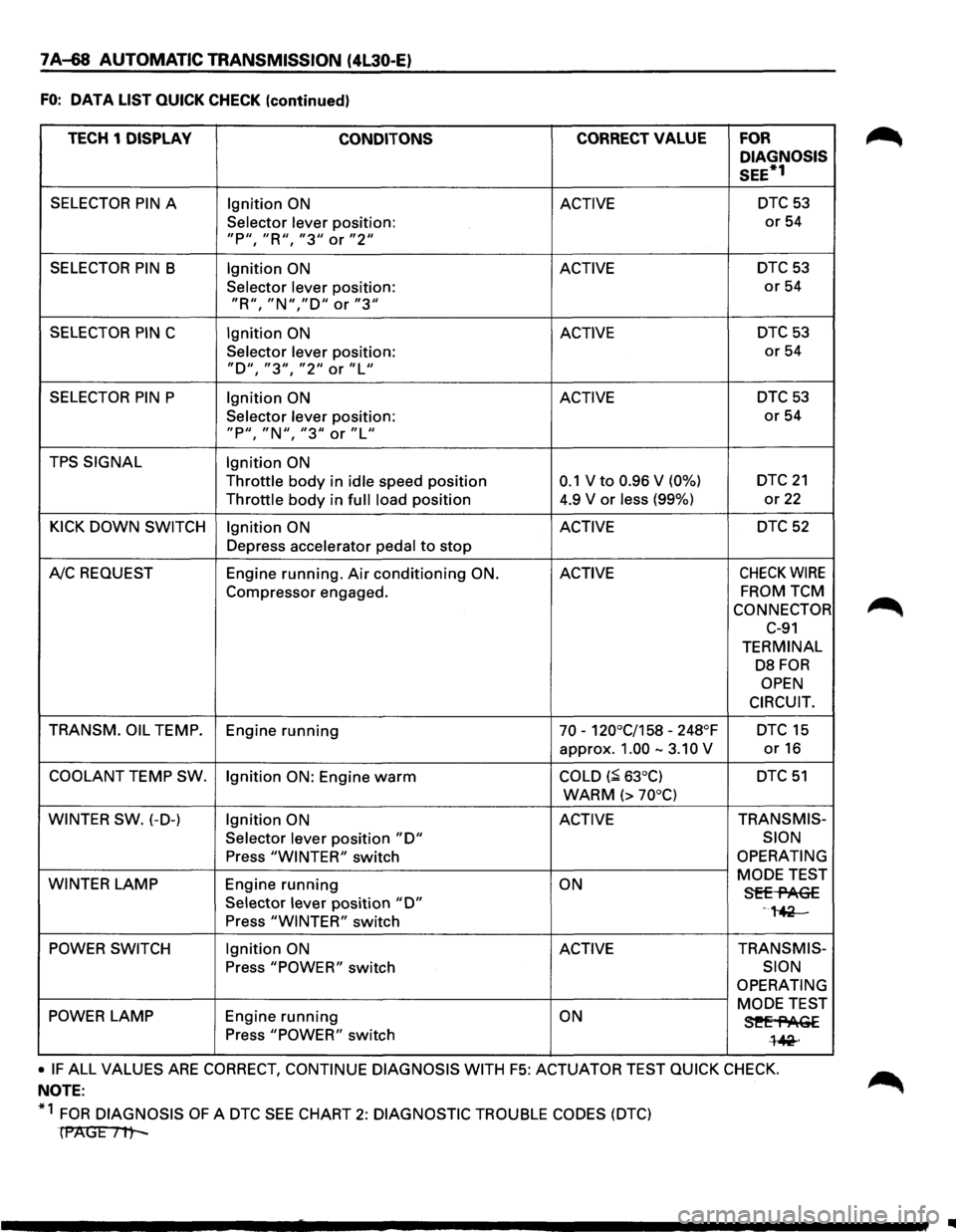
7A-68 AUTOMATIC TRANSMISSION (4l30-E)
FO: DATA LIST QUICK CHECK (continued)
TECH 1 DISPLAY
CONDITONS CORRECT VALUE FOR
DIAGNOSIS
SEE*1
SELECTOR PIN A Ignition ON ACTIVE DTC 53
Selector lever position: or 54
"P11, "R'', "311 or "211
SELECTOR PIN B Ignition ON ACTIVE DTC53
Selector lever position: or 54
"R11
, "N","D'' or "3''
SELECTOR PIN C Ignition ON ACTIVE DTC 53
Selector lever position: or 54
"D'', "311
, "211 or "L''
SELECTOR PIN P Ignition ON ACTIVE DTC 53
Selector lever position: or 54
"P11
, "N11, "311 or "Lu
TPS SIGNAL Ignition ON
Throttle body in idle speed position 0.1 V to 0.96 V (0%) DTC 21
Throttle body in full load position 4.9
V or less (99%) or 22
KICK DOWN SWITCH Ignition ON ACTIVE DTC 52
Depress accelerator pedal to stop
A!C REQUEST Engine running. Air conditioning ON. ACTIVE CHECK WIRE
Compressor
engaged. FROM TCM
CONNECTOR
C-91
TERMINAL
DB FOR
OPEN
CIRCUIT.
TRANSM. OIL
TEMP.
Engine running 70 -120°C/158 -248°F DTC 15
approx. 1.00 -3.10 V or16
COOLANT TEMP SW.
Ignition ON: Engine warm COLD (~ 63°C) DTC 51
WARM (> 70°C)
WINTER SW.
(-D-) Ignition ON ACTIVE TRANS
MIS-
Selector
lever position "D" SION
Press "WINTER" switch OPERATING
WINTER
LAMP Engine running ON MODE
TEST Sff-flAG£ Selector lever position "D" -,~ Press "WINTER" switch
POWER SWITCH Ignition ON ACTIVE TRANSMIS-
Press "POWER" switch SION
OPERATING
POWER LAMP Engine running ON MODE TEST
3!'Ef'AGE Press "POWER" switch l~·
• IF ALL VALUES ARE CORRECT, CONTINUE DIAGNOSIS WITH F5: ACTUATOR TEST QUICK CHECK.
NOTE:
*1
FOR DIAGNOSIS OF A DTC SEE CHART 2: DIAGNOSTIC TROUBLE CODES (DTC)
(PAGE Itt-
IIIII
Page 1191 of 1928

CHASSIS ELECTRICAL 8-1
·SECTION 8
CHASSIS ELECTRICAL
'\f CAUTION: .
When fasteners are removed, always reinstall them at the same location from which they were removed.
If a fastener needs to be replaced, use the correct part number fastener for that application. If the correct
part number fastener is not
available, a fastener of equal size and strength (or stronger) may be used.
Fasteners that are not reused, and those requiring thread
locking compound, will be called out. The correct
torque
values must be used when installing fasteners that require it. If the above conditions are not
followed, parts or system damage could result.
CONTENTS
General Information .................................... 8-2
Notes for Working on Electrical
Items .................................................... 8-2
Symbols and Abbreviations ................. 8-8
Symbols ............................................ 8-8
Abbreviations ................................... 8-9
Parts for Electrical Circuit ..................... 8-10
Wiring ............................................... 8-10
Fuse .................................................. 8-11
Fusible Link ....................................... 8-12
Circuit Breaker ................................... 8-12
Relay ................................................. 8-12
Relay Specifications and
Configurations ................................ 8-13
Diode ................................................. 8-14
Connector ......................................... 8-15
Reading the Circuit Diagram ................ 8-17
Main Data and Specifications .................... 8-19
Bulb Specifications ................................ 8-19
Fuse,
Fusible Link and
Circuit Breaker Location ..................... 8-21
Fuse
Block Circuit .................................. 8-22
Reference Table of Fuse, Fusible
Link and Circuit Breaker ..................... 8-23
Relay Location ....................................... 8-27
Diode Location .......................................
8-28
Grounding Point .................................... 8-29
Reference Table ................................ 8-29
Location ............................................ 8-31
Cable Harness Routing .......................... 8-34
System Repair .............................................. 8-38
Start and Charging ................................ 8-38
Engine Control Module
(ECM) ................................................... 8-47
Headlight and Fog Light ........................ 8-58
Front Side Marker Light, Parking Light,
Taillight, License Plate Light and
Illumination Light .............................. 8-76
Stoplight and Rear Defogger .............. 8-92
Turn Signal Light, Hazard
Warning
Light, Cornering Light,
Backup
Light and Horn ..................... 8-106
Dome Light, Luggage room Light,
Courtesy Light, Map Light,
Seat Belt Switch and
Warning Buzzer ................................. 8-128
Power Door Lock ................................. 8-142
Power
Window .................................... 8-156
Cruise
Control ...................................... 8-172
Anti-Lock Brake
System (ABS) ........... 8-178
Rear
Wheel Anti-Lock Brake
System (RWAL) ................................. 8-185
Transmission
Control Module
(TCM) ................................................. 8-192
A/T Shift Lock ...................................... 8-200
Windshield
Wiper/Washer and
Rear
Wiper/Washer .......................... 8-205
Headlight wiper /washer ..................... 8-232
Audio, Auto Antenna,
Cigarette
Lighter and digital clock ... 8-246
Power Door Mirror ............................... 8-254
Anti-theft System ................................ 8-270
Meter and Warning/Indicator Light ... 8-288
A/T Shift Indicator ............................... 8-336
Heater and
Air Conditioning ............... 8-340
Sun
Roof ............................................... 8-346
Power Seat ........................................... 8-360
Seat
Heater .......................................... 8-37 4
Supplemental Restraint
System (SRS) -AIR BAG ................... 8-382
Page 1209 of 1928
CHASSIS ELECTRICAL 8-19
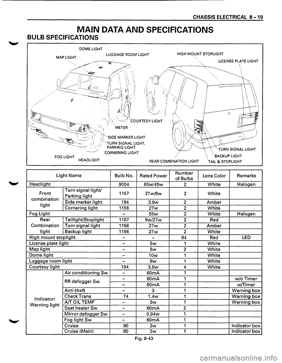
MAIN DATA AND SPECIFICATIONS
BULB SPECIFICATIONS
DOME LIGHT
MAP LIGHT LUGGAGE ROOM LIGHT HIGH MOUNT STOPLIGHT
FOG LIGHT HEADLIGHT
Light Name
Bulb No.
Headlight
9004
Front Turn
signal light/ 1157 Parking light combination Side marker light 194 light Cornering light 1156
Fog Light
-
Rear Taillight/Stoplight 1157
Combination Turn signal
light 1156
light Backup light 1156
High
mount stoplight -
License plate light -
Map light -
Dome light -
Luggage room light -
Courtesy light 194
Air conditioning Sw -
-
RR defogger Sw -
Anti-theft -
Indicator/ Check
Trans 74
Warning light A/TOIL TEMP -
Seat heater Sw -
Mirror defogger Sw -
Fog light Sw -
Cruise 80
Cruise (Main) 80
""·
,/
REAR COMBINATION LIGHT
Rated Power Number
of Bulbs
65w/45w 2
27w/8w 2
3.8w 2
27w 2
55w 2
8w/27w 2
27w 2
27w 2
-84
5w 1
5w 2
10w 1
8w 1
3.8w 4
60mA 1
60mA 1
SOmA 1
3 1
1.4w 1
3w 1
60mA 2
0.94w 1
60mA 1
2w 1
2w 1
Fig. 8-43
\BACKUP LIGHT
TAIL & STOPLIGHT
Lens Color Remarks
White Halogen
White
Amber
White
White Halogen
Red
Amber
White
Red LED
White
White
White
White
White
w/oTimer
w/Timer
Warning box
Warning box
Warning box
Indicator box
Indicator box
Page 1212 of 1928
8-22 CHASSIS ELECTRICAL
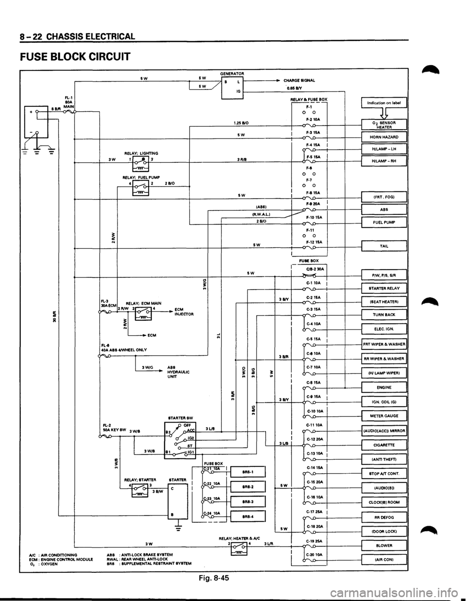
FUSE BLOCK CIRCUIT
GENERATOR -------------------~s~w~------------~~s~w~--~~~~ r- / B L 1------CHARGE SIGNAL &W _/
FL-1 80A .-----, B 11.'1 MAIN
+ Lt--
l£h
~----/ IG~----------~O~.$~B/V~-----------,
3W REL~HT1NG 1J ---'"~L 3
RELA~PUMP 4 1...---. 12 2 B/0
1.25 B/0
SW
3RJ8
5W
~~~·~ F-1 0 0 F-2 10A
I F-315A
F-8
0 0 F-7 0 0 F-81SA
F-920A
9;nlaool
I
Oz SENSOR HEATER
HORN HAZARD
H/LAMP-LH
H/LAMP-RH
(FRT. FOG)
lABS) -I ABS
I ,--------__:<;;:R·.:.:W.::..Acc·L;;:-1 ____ ----Jv F-10 1SA 2 810
I
~ECM RELAY; ECM MAIN ¢~,...,..J>--+2'-'RIW~_::2~1-o.....-<:>-f-·4.:._ __ _. ~J~CTOR
L...-_.ECM
FL-t 40A ABS 4/WHEEL ONLY
"
.... ...
SW
5W
3 8IY
F-11 0 0 F-1215A
~------' FUSE BOX
CIB-2 30A ~.,.;
C-110A :
C-215A
C-31SA
C-410A
I
J
FUEL PUMP
TAIL
P/W, PIS. SIR
STARTER RELAY
(SEAT HEATER)
TURN BACK
ELEC.IGN.
e-s
15A 1 ""'-.0---t-----+----il FRT WIPER & WASHER
"""' -
I 3W/G
C-810A '---f-+----+.:3.:BIR::::..+---¢""''-£>---i-----f-----jl RR WIPER & WASHER
ABS HYORAULIC UNIT
STARTERSW
FL-2 _JJ OFF
~ ...
..:..AKEYSW 3 W/B ay ' o.N". 3UB
~~--~--~,~------~-0 ~~IG~2Y-----------~ o-: ST 3W/B 81 -.,IG1
FUSE BOX
I
I g1~ 1 J'-:::s:R:s-:1 =I RELAY; STARTER
STARTER I r-
L~---'~-j.t
I I 3UB
sw
C-710A
~';::--~--~-'---~~~HI~LA~M~P~W~IP~E~R~l~~ C-81SA ""'-'>--1---...__---i ENGINE
C-111SA I J~======~l IGN. COIL (G)
C-10 10A
C-1110A
k'-1:>----t----t
~==~I
METER GAUGE
""''-£>---f----------1 (AUDIO[ACC)) MIRROR
C-12 20A
::...1310A I
C-141SA -r"\'-1)----f----t
C-15 20A L,-.
CIGARETTE
(ANTITHEFT)
STOP A/T CONT.
(AUDIO[ B))
C-1810A """"-'-.0---f----------t_j CLOCK[B) ROOM
L---+------------------------iB lt~;_ ~=~~~:~:~::~~~: C-17 2SA I
G1820A
RR DEFOG
= sw (DOOR LOCK) RELAY; HEATER &A/C .:._ __________________ .:.:3~W'-'---------------------~2to~.....-4 3UR C-19 2SA ...... BLOWER
A/C : AIR CONDITIONING ECM : ENGINE CONTIIOL MODULE 0, :OXYGEN ABS
:ANTI-LOCK
BRAKE BYBTEM
RWAL: REAR WHEEL ANTI-LOCK BRB : SUPPLEMENTAL RESTRAINT SYSTEM
C-20 10A (AIR CON)
Fig. 8-45
•
Page 1217 of 1928
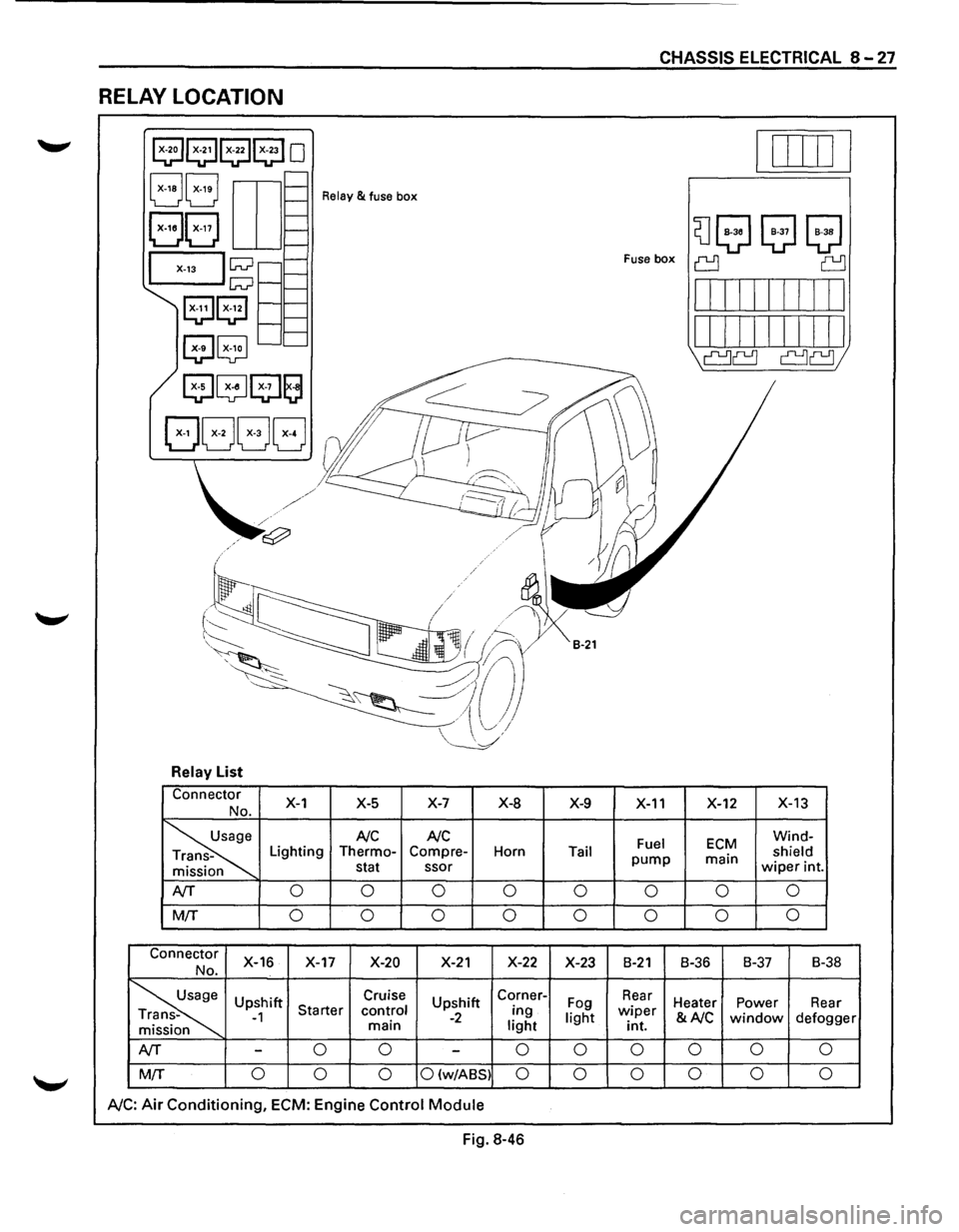
RELAY LOCATION
Relay & fuse box
Relay List
Connector X-1 X-5 X-7
X-8
No.
~
NC NC Lighting Thermo-Com pre-
Horn -stat ssor
n
NT 0 0 0 0
M(f 0 0 0
0
Connector
X-16 X-17 X-20 X-21 X-22
No.
~
Upshift Cruise Upshift Corner-
-1 Starter control -2 ing -main light n
NT -0 0 -0
M!f 0 0 0 0(w/A8S) 0
AJC: Air Conditioning, ECM: Engine Control Module
Fig. 8-46
B-21
X-9
Tail
0
0
X-23
Fog
light
0
0
CHASSIS ELECTRICAL 8-27
Fuse box
X-11
Fuel pump
0
0
8-21
II]]]J I
~8~8
c:J c:J
11111111111
111111
IIIII
BB a B
X-12 X-13
ECM Wind-
main shield wiper int.
0
0
0 0
8-36
8-37
8-38
Rear Heater Power Rear
wiper int. &NC window defogger
0
0 0
0
0 0 0
0