air conditioning ISUZU TROOPER 1995 Workshop Manual
[x] Cancel search | Manufacturer: ISUZU, Model Year: 1995, Model line: TROOPER, Model: ISUZU TROOPER 1995Pages: 1928
Page 1218 of 1928
8-28 CHASSIS ELECTRICAL
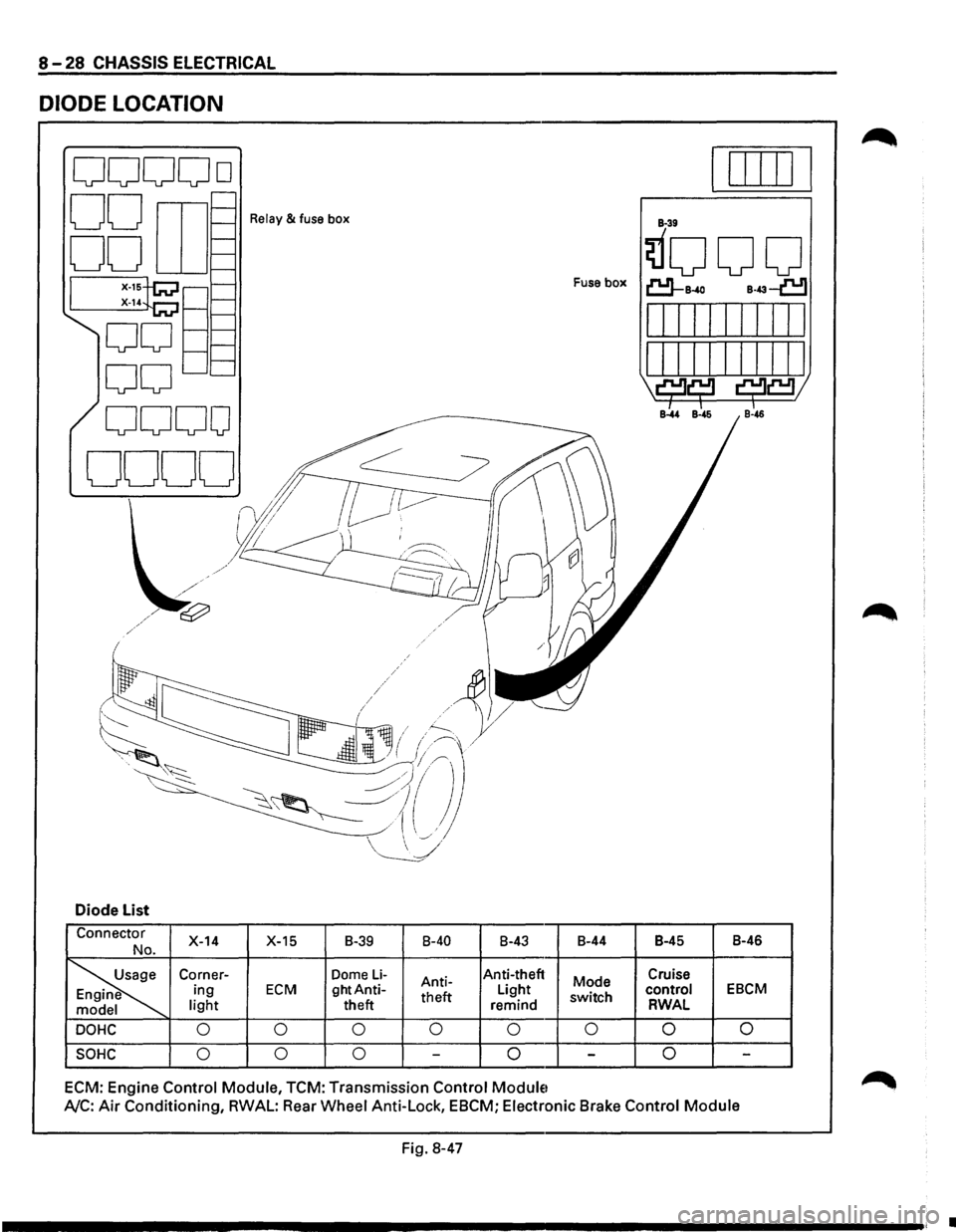
DIODE LOCATION
Relay & fuse box
Fuse box
Diode List
Connector X-14
X-15 B-39 8-40 8-43 8-44
B-45 8-46 No.
~
Corner-Dome Li-Anti-Anti-theft
Mode Cruise ing ECM ghtAnti-
theft Light
switch control EBCM
light
theft remind RWAL
DOHC 0
0 0 0
0 0 0 0
SOHC 0
0 0 -0 -0 -
ECM:
Engine Control Module, TCM: Transmission Control Module1
A/C: Air Conditioning, RWAL: Rear Wheel Anti-Lock, EBCM; Electronic Brake Control Module
Fig. 8-47
•
Page 1220 of 1928
8-30 CHASSIS ELECTRICAL
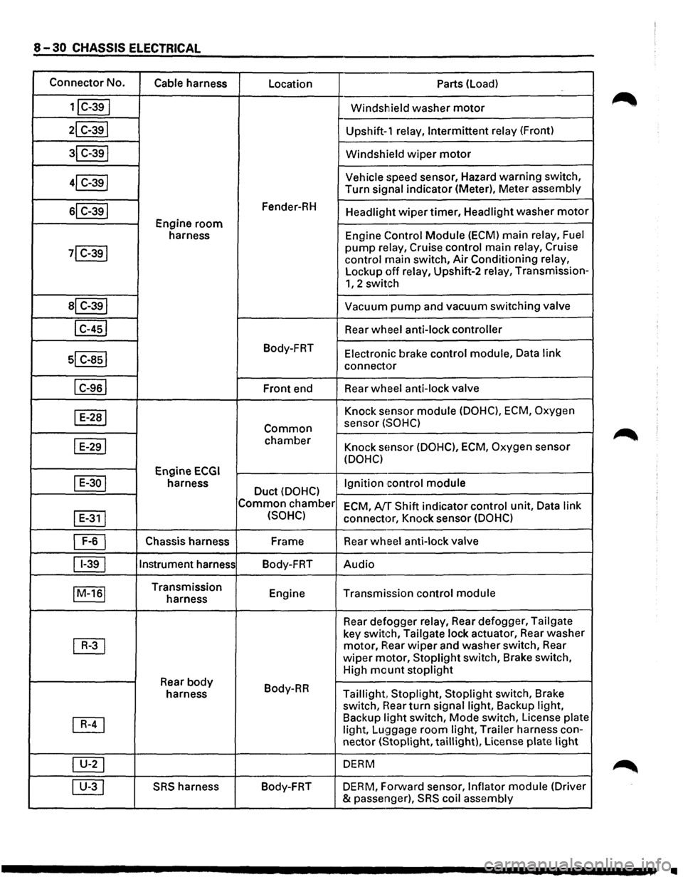
Connector No.
Cable harness
Location Parts (load)
1jC-39I Windshield washer motor
21 C-391 Upshift-1 relay, Intermittent relay (Front)
31 C-391 Windshield wiper motor
41 C-39j Vehicle speed
sensor, Hazard warning switch,
Turn
signal indicator (Meter), Meter assembly
sl C-391 Fender-RH Headlight wiper timer, Headlight washer motor
Engine room
harness Engine Control Module (ECM)
main relay, Fuel
71 C-391 pump relay, Cruise control main relay, Cruise
control main switch, Air Conditioning relay,
Lockup off relay, Upshift-2 relay, Transmission-
1, 2 switch
al C-391 Vacuum pump and vacuum switching valve
I C-451 Rear wheel anti-lock controller
sl c-asl
Body-FRT Electronic brake control module, Data link
connector
I C-961 Front end Rear wheel
anti-lock valve
I E-281 Knock sEmsor module (DOHC), ECM, Oxygen
Common sensor (SOHC)
I E-291 chamber Knock sensor (DOHC), ECM, Oxygen sensor
(DOHC)
Engine
ECGI
I E-30 I harness Duct (DOHC) Ignition control
module
Common chamber
ECM, AfT Shift indicator control unit, Data link
I
E-311 (SOHC) connector, Knock sensor (DOHC)
~ Chassis harness Frame
Rear wheel anti-lock valve
11-391 Instrument
harness
Body-FRT Audio
IM-161 Transmission
Engine Transmission control module harness
Rear defogger
relay, Rear defogger, Tailgate
~
key switch, Tailgate lock actuator, Rear washer
motor, A:ear wiper and washer switch, Rear
wiper motor, Stoplight switch, Brake switch,
High
mount stoplight
Rear body Body-RR
harness Taillight, Stoplight, Stoplight switch, Brake
switch,
near turn signal light, Backup light,
~
Backup light switch, Mode switch, License plate
light, Lu!;)gage room light, Trailer harness con-
nector
(Stoplight, taillight), License plate light
~ DERM
00 SRS harness Body-FRT
DERM, Forward sensor, Inflator module (Driver
& passenger),
SRS coil assembly
•
Page 1235 of 1928
OFF
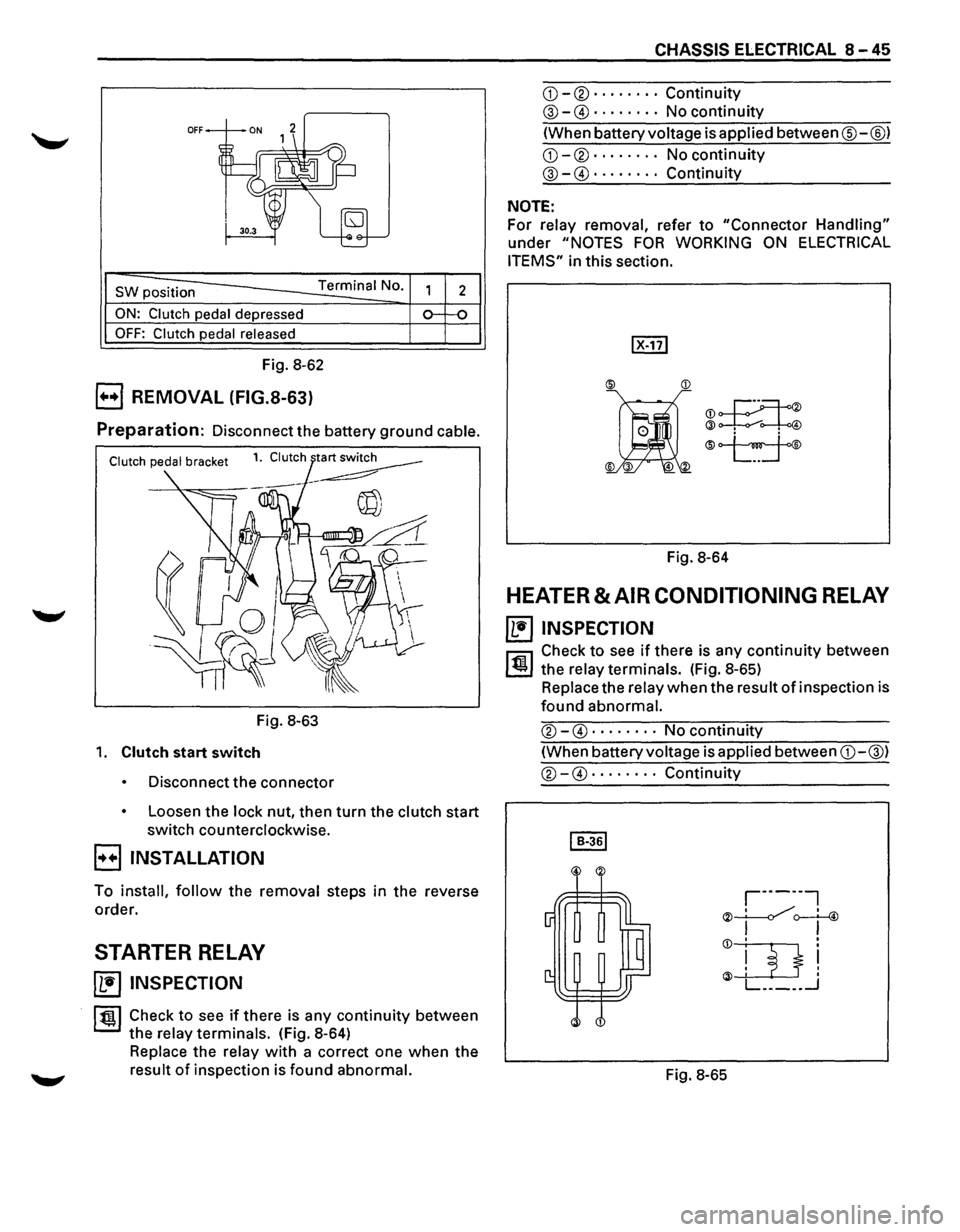
SW position Terminal No.
ON: Clutch pedal depressed
OFF: Clutch pedal released
Fig. 8-62
B REMOVAL (FIG.S-63)
2
Preparation: Disconnect the battery ground cable.
Fig. 8-63
1. Clutch start switch
Disconnect the connector
Loosen the lock nut, then turn the clutch start
switch counterclockwise.
B INSTALLATION
To install, follow the removal steps in the reverse
order.
STARTER RELAY
~ INSPECTION
ltgl Check to see if there is any continuity between
the relay terminals. (Fig. 8-64)
Replace the relay with a correct one when the
result of inspection is found abnormal.
CHASSIS ELECTRICAL 8-45
CD-®······ · · Continuity
@-G)· . · · · · .. No continuity
(When battery voltage is applied between®-@)
CD-®· · · · · · · · No continuity
@-G)· · · · · · · · Continuity
NOTE:
For relay removal, refer to "Connector Handling"
under "NOTES FOR WORKING ON ELECTRICAL
ITEMS"
in this section.
®JI
@~
®
Fig. 8-64
HEATER & AIR CONDITIONING RELAY
~ INSPECTION
l'fll Check to see if there is any continuity between
~ the relay terminals. (Fig. 8-65)
Replace the relay when the result of inspection is
found abnormal.
®-G) ..... · .. No continuity
(When battery voltage is applied between CD-@)
®-G) .... · · .. Continuity
Fig. 8-65
Page 1237 of 1928
CHASSIS ELECTRICAL 8-47
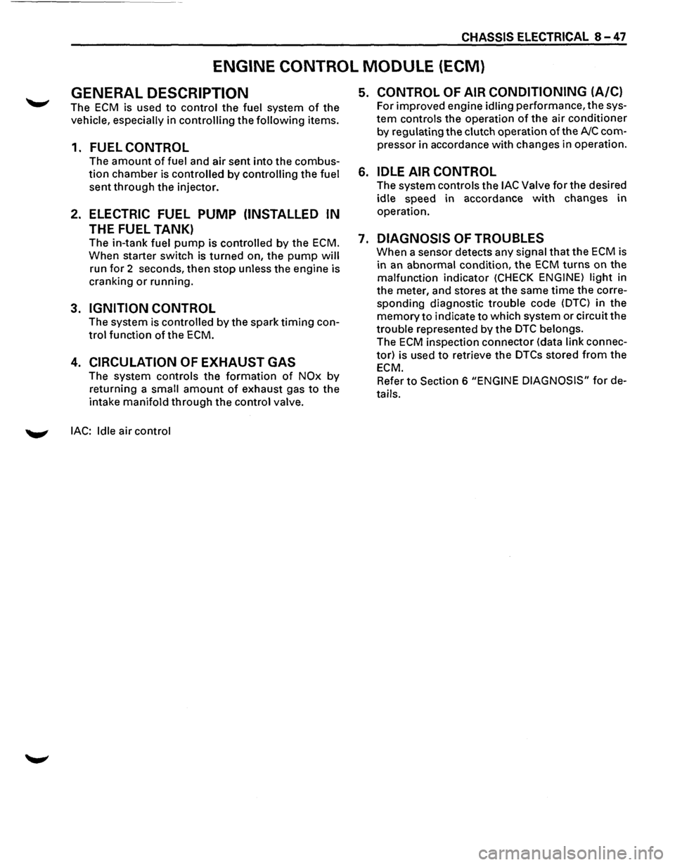
ENGINE CONTROL MODULE (ECM)
GENERAL DESCRIPTION
The ECM is used to control the fuel system of the
vehicle, especially in controlling the following items.
1. FUEL CONTROL
The amount of fuel and air sent into the combus
tion chamber is controlled by controlling the fuel
sent through the injector.
2. ELECTRIC FUEL PUMP (INSTALLED IN
THE FUEL TANK)
The in-tank fuel pump is controlled by the ECM.
When starter switch is turned on, the pump will
run for 2 seconds, then stop unless the engine is
cranking
or running.
3. IGNITION CONTROL
The system is controlled by the spark timing con
trol function of the ECM.
4. CIRCULATION OF EXHAUST GAS
The system controls the formation of NOx by
returning a small amount of exhaust gas to the
intake manifold
through the control valve.
'-" lAC: Idle air control
5. CONTROL OF AIR CONDITIONING (A/C)
For improved engine idling performance, the sys
tem controls the operation of the air conditioner
by regulating the
clutch operation ofthe A/C com
pressor in accordance
with changes in operation.
6. IDLE AIR CONTROL
The system controls the lAC Valve for the desired
idle speed in accordance
with changes in
operation.
7. DIAGNOSIS OF TROUBLES
When a sensor detects any signal that the ECM is
in
an abnormal condition, the ECM turns on the
malfunction
indicator (CHECK ENGINE) light in
the meter, and stores at the same
time the corre
sponding diagnostic
trouble code (DTC) in the
memory to indicate to which system or circuit the
trouble represented by the
DTC belongs.
The ECM inspection connector (data link connec
tor) is used
to retrieve the DTCs stored from the
ECM.
Refer to Section 6 "ENGINE DIAGNOSIS" for de
tails.
Page 1241 of 1928
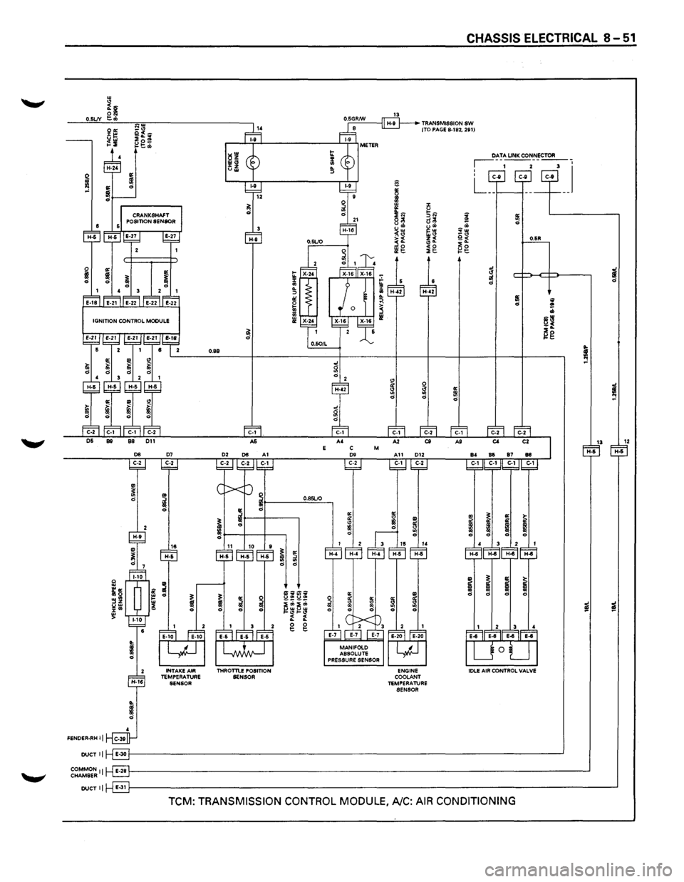
w " ~~ O.SLJY ~ ..
2"' a~ u$ ~f~ ~~ ~g~
FENDER-RH II
DUCT II
~~~~~II
DUCT II
INTAKE AIR TEMPERATURE SENSOR
~~ 0~
a; d
0.89
C-1 A&
THROTTLE POSITION
SENSOR
... 5! ., .. ::> 0: ~
m
0.85LIO
~ a d d
li~Ui"o:i UOlUCJI> i;i;i:b ~wuw "'"" ~ ~ g g
"' il " Ill
13
§
; w 0 0: .. 5N ~;:; 8<:1 d~ u"' ~~ ~~ ~~ z< ., .. ~g ~g
~ § :;1 ~ d
0: " Ill d
ENGINE COOLANT
TEMPERATURE
SENSOR
CHASSIS ELECTRICAL 8-51
~ ~ ~w _.,
i£ ~g
~ i ;zf d
d
IIi ~ d .. :b
~~ ~g
~
"' ~ 5I d "'
13 12 H-6 H-6
.. ~ "' ~ il il
!
! ! ~
~ ~ I ~ CD ! ! ~
i
i
TCM: TRANSMISSION CONTROL MODULE, A/C: AIR CONDITIONING
Page 1243 of 1928
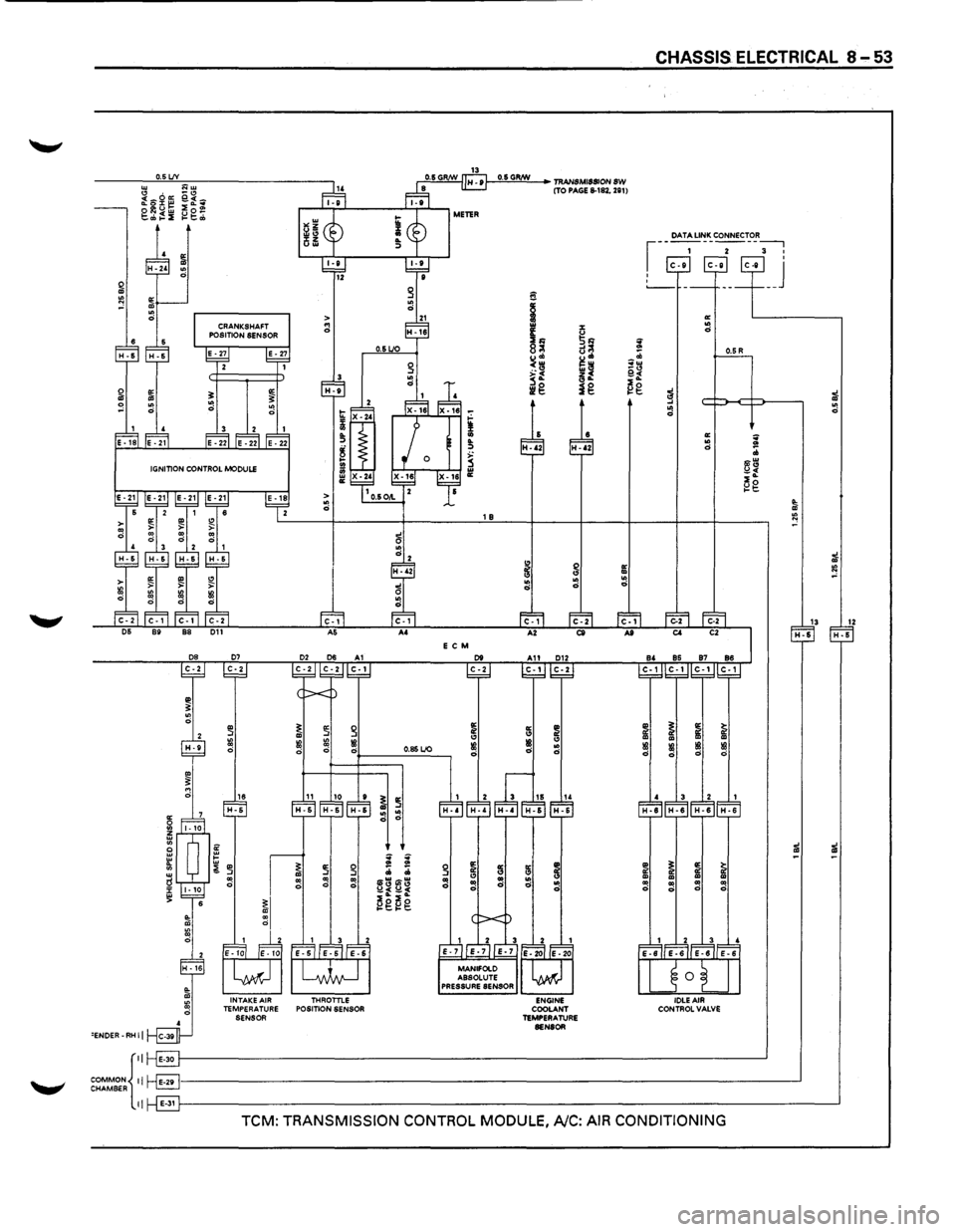
0.5 LJV
E C M
.. ~ ~ g ~ ::r <3 ::! ~ ~ IB Ill d 0 d 0.85 LJO d
16 10 ~ ~ H-6 ~ ~
: : 3 ~ ~ ;;; ;;; .. 3~ ~~ ~ " 0 ~ I -f -:
~I
~g~g
INTAKE AIR THROTTLE TEMPERATURE POSITION SENSOR
SENSOR
'ENDER-RH II
f-'0""·5,;G,RIN!!!!.__,~ TRANSMISSION SW (TO PAGE 8-182. 281)
a
~ .. % IE u 21<1 3~ i 8<=~
~= u .. ;;;
~~ '"'" ~~
_.., j§L e.~ 2o ll!g ig l:!t::
a: ~ i <3 <3 IB .. IB d
d
d
a: a: ~ ~ <3 " .. .. .. d d ~ ~
CHASSIS ELECTRICAL 8 ... 53
~ ... .. d
~ ..
~
~ .. ~
i IB d
~ .. ~
a: .. d
13 1Z H-5 H-5
i IB d
iil iil
~ .. .. 0
COMMON{::~------------------------------------------------------------------------------------------~ CHAMBER r·-l::.:!!J
II E-311-'----------------------------------------------------------------------------------------------~
TCM: TRANSMISSION CONTROL MODULE, A/C: AIR CONDITIONING
Page 1529 of 1928
'"T1 cO' co w
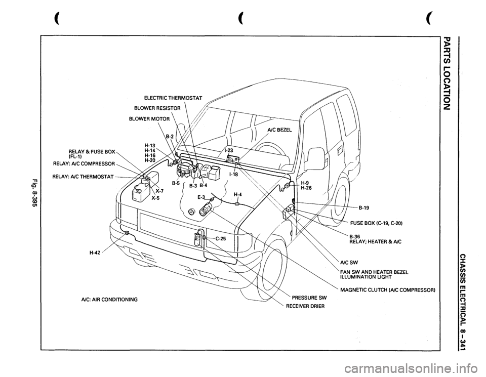
RELAY
& FUSE
BOX
(FL-11
RELAY:
NC
COMPRESSOR
BLOWER
MOTOR
RELAY:
NCTHERMOSTAT
,,-;~
H-42'
NC:
AIR
CONDITIONING
(
PRESSURE
SW
RECEIVER
DRIER
B-19
FUSE
BOX
(C-19,
C-201
B-36 RELAY;
HEATER
& NC
NCSW FAN
SW
AND
HEATER
BEZEL
ILLUMINATION
LIGHT
(
MAGNETIC
CLUTCH
INC
COMPRESSOR)
;g ::0 ~ r-0 0 ~ 0 2
n :::J: )> en en Cii m rm ~ ::u n )> r-eo I w ~ ...a
Page 1530 of 1928
![ISUZU TROOPER 1995 Workshop Manual 8 -342 CHASSIS ELECTRICAL
CIRCUIT DIAGRAM
~ IOOV
M:LAV; 8TARTERI1) ITO PAOEI· .. I
E!]~ ENG. ftAME
. :l
. 5
IOOV-11< II
2L
I LOWER MOTOR
fiiELAY; HEATEfii6AIC
C·1t 21A BLOWER
A/C: AI](/img/61/57183/w960_57183-1529.png "ISUZU TROOPER 1995 Workshop Manual 8 -342 CHASSIS ELECTRICAL
CIRCUIT DIAGRAM
~ IOOV
M:LAV; 8TARTERI1) ITO PAOEI· .. I
E!]~ ENG. ftAME
. :l
. 5
IOOV-11< II
2L
I LOWER MOTOR
fiiELAY; HEATEfii6AIC
C·1t 21A BLOWER
A/C: AI")
8 -342 CHASSIS ELECTRICAL
CIRCUIT DIAGRAM
~ IOOV
M:LAV; 8TARTERI1) ITO PAOEI· .. I
E!]~ ENG. ft'AME
. :l
. 5
IOOV-11< II
2L
I LOWER MOTOR
'
fiiELAY; HEATEfii6AIC
C·1t 21A BLOWER
A/C: AIR CONDITIONING
O.IIR O.IIR
IOOV~ 11~----------------------------------------------------------__J
Fig. 8-396
22
H·11
..
Page 1532 of 1928
8-340 CHASSIS ELECTRICAL
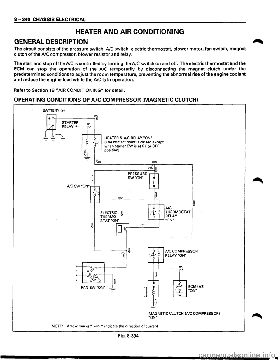
HEATER AND AIR CONDITIONING
GENERAL DESCRIPTION
The circuit consists of the pressure switch, NC switch, electric thermostat, blower motor, fan switch, magnet
clutch of the NC compressor, blower resistor and relay.
The start and stop of the NC is controlled by turning the NC switch on and off. The electric thermostat and the
ECM can stop the operation of the NC temporarily by disconnecting the magnet clutch under the
predetermined conditions
to adjust the room temperature, preventing the abnormal rise of the engine coolant
and reduce the engine load while the NC is in operation.
Refer
to Section 18 "AIR CONDITIONING" for detail.
OPERATING CONDITIONS OF A/C COMPRESSOR (MAGNETIC CLUTCH)
BATIERY(+)
--
~
A/C SW "ON"
~
HEATER & A/C RELAY "ON"
(The contact point is closed except
when starter SW is at ST or OFF position)
(S =:>
¢:!]
PRESSURE D
SW"ON"
¢:::l
~ FAN SW"ON"
u A/C THERMOSTAT
RELAY
"ON"
A/C COMPRESSOR
RELAY"ON"
ECM IA2l "ON"
MAGNETIC
CLUTCH lAIC COMPRESSOR)
"ON"
NOTE:
Arrow marks" =:> " indicate the direction of current
Fig. 8-394
~
1111
Page 1787 of 1928
ORDER OF REMOVAL/INSTALLATION STEPS FOR EACH ITEM
Removal Item
1. Front console assembly
2. Lower cluster assembly
3. Glove box
4. Instrument panel passenger lower cover
5. Passenger knee bolster reinforcement
6. Instrument panel driver lower cover
7. Driver knee bolster
8. Front defroster grille
9. Instrument panel assembly
10. Passenger inflator module
11.1nstrument panel cluster
12. Meter assembly
13. A/C control panel assembly
14. Radio antenna cable
15. Radio assembly
16. Vent duct assembly
17 .Instrument harness assembly
18. Side defroster grille
MfT; Manual Transmission
A/T;
Automatic Transmission Removal
Procedure
Shift
knob(MfT), Power&Winter SW(A/T),
Transfer knob, Seat heater/Miller SW conn.
and 4 screws
3 screws, Ciger lighter conn. and
Ashtray illumination conn.
2 screws
7 screws and 1 clip
4 nuts & 4 bolts
Engine hood opener fixing screw, 2 screws, 1 bolt, 1 clip and fasteners at 4 position.
6 nuts
Claws at 8 position
2 bolts (SRS adjust bracket-Cross beam), A!C control cable (Unit side at 3 position), Instrument harness conn. (Driver side 5 position,
Assist side 3 position), SRS module conn.,
Radio antenna juck, Earth
cable, 9 bolts and 3 nuts
4 nuts (SRS module-Instrument panel), 2 nuts and 2 washers (SRS module-support bracket)
and 2 clips
5 screws, fastener at 4 position and each SW conn.
4 screws and connectors
4 screws and connectors
4 screws
5 screws
4 screws, fasteners at 4 position, and clips at 7 position.
SRS; Supplemental Restraint System
A!C; Air Conditioning
BODY 10-29
Removal Step
1~2
1~3~4
1~5
1~2~6
1~2~6~7
1-3~4
1~9
1-5~10
1~2~6~11
1~2~6~11~12
1-7~11~13
1-7~11~13~14
1~7~11~13~14~15
1-9~15~16
1-9~16