air conditioning ISUZU TROOPER 1995 Manual PDF
[x] Cancel search | Manufacturer: ISUZU, Model Year: 1995, Model line: TROOPER, Model: ISUZU TROOPER 1995Pages: 1928
Page 702 of 1928
6E2-6 DRIVEABILITY AND EMISSIONS
FIELD SERVICE MODE
ENGINE
CONTROL MODULE (ECM)
LEARNING ABILITY
The Engine Control Module (ECM) has a
"learning"
ability which allows it to make
corrections
for minor variations in the fuel system
to improve driveability. If the battery is
disconnected to clear diagnostic codes, or for
repair, the "learning" process has to begin all over
again. A change
may be noted in the vehicle's
performance. To "teach" the vehicle, make sure
the engine is at operating temperature, and drive
at part throttle, with moderate acceleration and
idle conditions, until normal performance returns.
lfthe diagnostic test terminal is grounded with the
engine running, the system is in
"Open" or
"Closed Loop".
In "Open Loop" the "Check Engine" malfunction
indicator lamp flashes
two and one-halftimes per
seconds.
In "Closed Loop", the light flashes once per
second.
Also, in "Closed
Loop", the light will stay "OFF"
most of the time if the system is too lean. It will
stay"ON" mostofthetime if the system is too rich.
While the system is in Field Service Mode, the
ECM will be in the following diagnostic test mode:
1. New trouble codes cannot be stored in the
ECM.
2. The closed loop timer is bypassed.
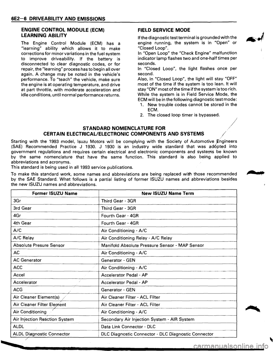
STANDARD NOMENCLATURE FOR /
CERTAIN ELECTRICAL/ELECTRONIC COMPONENTS AND SYSTEMS /
Starting with the 1993 model, lsuzu Motors will be complying with the Society of Automotive ~ngineers
(SAE) Recommended Practice J 1930. J 1930 is an industry wide standard that was ad6pted into
government regulations and requires certain electrical and electronic components and
syster;ns be known
by the same
nomenclature that have the same function. This standard is also being applied to
abbreviations and acronyms.
This standard is being used in
all 1993 service publications.
To make this standard work, some names and abbreviations are being replaced
with those recommended
by the
SAE Standard. What follows is a partial listing of former ISUZU names and abbreviations besides
the
new ISUZU names and abbreviations.
Former ISUZU Name New ISUZU Name Term
3Gr
Third Gear -3GR
3rd Gear
Third Gear -3GR
4Gr
Fourth Gear -4GR
4th Gear
Fourth Gear -4GR
A/C Air Conditioning -A/C
A/C
Relay Air Conditioning Relay -A/C Relay
Absolute Presure Sensor
Manifofd Absolute Pressure Sensor -MAP Sensor
AC Air Conditioning -A/C
AC Generator . Generator -GEN
ACC Air Conditioning -A/C
Accel
Accelerator Pedal -AP
Accelerator
Accelerator Pedal -AP
ACG Generator -GEN
Air Cleaner Element(s) / Air Cleaner Filter -ACL Filter
Air Cleaner Filter Ele;nent Air Cleaner Filter -ACL Filter
Air Conditioning / Air Conditioning -A/C
Air Injection Reaction System Secondary Air Injection System -AIR System
ALDL Data Link Connector -
DLC
ALDL Diagnostic Connector DLC Diagnostic Connector -DLC Diagnostic Connector ,.
, ....
Page 704 of 1928
6E2-8 DRIVEABILITY AND EMISSIONS
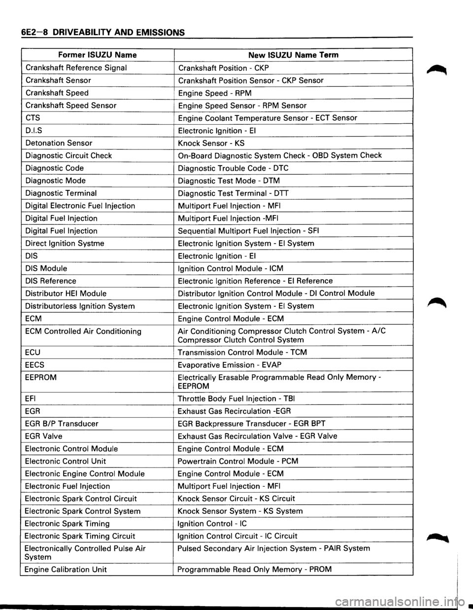
Former ISUZU Name New ISUZU Name Term
Crankshaft Reference Signal Crankshaft Position -CKP
Crankshaft Sensor
Crankshaft Position Sensor -CKP Sensor
Crankshaft Speed
Engine Speed -
RPM
Crankshaft Speed Sensor
Engine Speed Sensor -RPM Sensor
CTS Engine Coolant Temperature Sensor -ECT Sensor
D.I.S Electronic Ignition -El
Detonation Sensor
Knock Sensor-KS
Diagnostic Circuit Check On-Board Diagnostic System Check -OBD System Check
Diagnostic Code Diagnostic Trouble Code -DTC
Diagnostic Mode
Diagnostic Test Mode-DTM
Diagnostic Terminal
Diagnostic Test Terminal -DTT
Digital Electronic
Fuel Injection Multipart Fuel Injection -MFI
Digital Fuel Injection Multipart Fuel Injection -MFI
Digital Fuel Injection Sequential Multipart Fuel Injection -SFI
Direct Ignition Systme Electronic Ignition System -El System
DIS Electronic Ignition -El
DIS Module
Ignition Control Module -ICM
DIS Reference Electronic Ignition Reference -El Reference
Distributor
HEI Module Distributor Ignition Control Module -Dl Control Module
Distributorless Ignition System Electronic Ignition System -
El System
ECM Engine Control Module -ECM
ECM Controlled Air Conditioning Air Conditioning Compressor Clutch Control System -A/C
Compressor Clutch Control System
ECU Transmission Control Module -TCM
EECS Evaporative Emission-EVAP
EEPROM Electrically Erasable Programmable Read Only Memory-
EEPROM
EFI Throttle Body Fuel Injection -TBI
EGR Exhaust Gas Recirculation -EGR
EGR B/P Transducer EGR Backpressure Transducer -EGR BPT
EGR Valve Exhaust Gas Recirculation Valve -EGR Valve
Electronic Control Module Engine Control Module -ECM
Electronic Control Unit Powertrain Control Module -PCM
Electronic Engine Control Module Engine Control Module -ECM
Electronic Fuel Injection Multipart Fuel Injection -MFI
Electronic Spark Control Circuit Knock Sensor Circuit -KS Circuit
Electronic Spark Control System Knock Sensor System -KS System
Electronic Spark Timing Ignition
Control -IC
Electronic Spark Timing Circuit Ignition Control Circuit -IC Circuit
Electronically Controlled Pulse
Air Pulsed Secondary Air Injection System -PAIR System
System
Engine
Calibration Unit Programmable Read Only Memory -PROM
•
Page 712 of 1928
6E2-16 DRIVEABILITV AND EMISSIONS
LONG TERM (LT.) FUEL TRIM
There are from zero to seventeen different cells
which the Engine Control Module (ECM) learns at
depending on revolution per minute (rpm) and
manifold absolute pressure. This parameter
will
display what cell the ECM is using for the fuel
calculation at the time.
IDLE AIR CONTROL (lAC) COUNTS
This system is used to control engine idle speed to
the desired rpm, for different operating
conditions.
In this diagnostic test mode, the
numbers
will indicate what position the ECM
thinks the valve is in. The ECM moves the idle air
control in counts and these counts are displayed
on a
"Scan tool".
DESIRED REVOLUTION PER MINUTE
Indicates the rpm to which the ECM is trying to
control the idle.
AIR CONDITIONING (A/C) REQUEST
Displays the state of the Air Conditioning (A/C)
signal line to the ECM. Should read "YES"
whenever the A/C is requested.
AIR CONDITIONING {A/C) CLUTCH
Displays "ON" when the ECM has commanded
the
A/C Clutch "ON".
POWER STEERING PRESSURE (PSP)
SWITCH
Displays the state of switch. This reading may
vary
with the tool used and the type of switch
installed on the vehicle. The important thing is
that the reading changes state (switches) when
the steering is moved against the stops.
BA TTERV POSITIVE VOLTAGE
Displays the battery positive voltage detected at
the
ECM ignition input.
SPARK ADVANCE
This is a amount of total spark advance including
the base electronic ignition timing.
START UP ENGINE COOLANT
This parameter is the engine coolant temperature
at the
time the engine was started.
ENGINE SPEED (RPM)
RPM calculated during a crank mode, helpful in
diagnosing a NON-start condition.
FUEL TRIM ENABLE
This value is an indication when the Fuel Trim
Enable values are being updated within the ECM
program.
AIR/FUEL RATIO
This is the air to fuel ratio that is being
commanded to the injectors.
INDUCTION AIR CONTROL
The "Scan tool" will display the command being
given to the induction air control
plate system
solenoid.
SECTION B-DRIVEABILITY SYMPTOMS
Always start with Section "A" "On-Board Diagnostic
System Check" before proceeding to the driveability
symptoms.
Section "A" checks the ECM which may
cause the driveability problem. A definition
of each
symptom is included. This will then lead to the most
probable causes of the driveability problem.
SECTION C-COMPONENTS SYSTEMS
There are many component systems that are used to
control fuel and emissions. Section "C" introduces
each component system or control
with a general
description, diagnosis, and on-vehicle service.
Each
of the Section "C" diagnosis sections will contain
information on
how the "Scan tool" can be used for
diagnosing a particular component when a trouble
code has
not been set. (example: Section "C1" under
diagnosis
will explain how the "Scan tool" can be used
for diagnosis as well as what the normal readings
would be for the ECM Sensors.
•
Page 713 of 1928
DRIVEABILITY AND EMISSIONS 6E2-17
I OPERATING CONDITIONS READ I
I SYSTEMS CONTROLLED I
• Air Conditioning "On" or "Off" • Evaporative Emission Canister
• Engine Coolant Temperature Purge
• Crankshaft Position • Exhaust Gas Recirculation
• Exhaust Heated Oxygen Sensor • Ignition Control
• Electronic Ignition Reference • Fuel Control
• Crankshaft Position
ENGINE • Idle Air Control
• Engine Speed (RPM} CONTROL • Electric Fuel Pump
• Manifold Absolute Pressure (MAP)
MODULE • Air Conditioning
• Battery Positive Voltage (ECM) • Diagnostics
• Throttle Position Sensor • Malfunction Indicator Lamp
• Vehicle Speed Sensor • Diagnostic Test Terminal
• Fuel Pump Voltage • Data Output
• Power Steering Pressure • Transmission Control Module
• Intake Air Temperature • Knock Sensor (DOHC)
• Differential Pressure • Induction Air Control Plate System
• Knock Sensor (DOHC)
(DOHC)
• Exhaust Gas Recirculation Vacuum
• Air Conditioning High Side Pressure
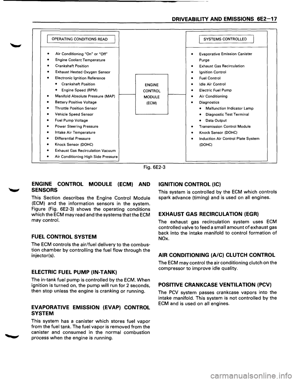
Fig. 6E2-3
ENGINE CONTROL MODULE (ECM) AND
SENSORS
This Section describes the Engine Control Module
(ECM) and the information sensors in the system.
Figure (Fig. 6E2-3) shows the operating conditions
which the
ECM may read and the systems thatthe ECM
may control.
FUEL CONTROL SYSTEM
The ECM controls the air/fuel delivery to the combus
tion chamber by
controlling the fuel flow through the
injector(s).
ELECTRIC FUEL PUMP (IN-TANK)
The in-tank fuel pump is controlled by the ECM. When
ignition is turned on, the
pump will run for 2 seconds,
then stop
unless the engine is cranking or running.
EVAPORATIVE EMISSION (EVAP) CONTROL
SYSTEM
This system has a canister which stores fuel vapor
from the fuel tank. The fuel vapor is removed from the
canister and consumed in the
normal combustion
process when the engine
is running.
IGNITION CONTROL (IC)
This system is controlled by the ECM which controls
spark advance (timing) and is used on all engines.
EXHAUST GAS RECIRCULATION (EGR)
The exhaust gas recirculation system uses ECM
controlled valve to feed a small amount of exhaust gas
back into the intake
manifold to control formation of
NOx.
AIR CONDITIONING (A/C) CLUTCH CONTROL
The ECM may control the air conditioning clutch on the
compressor
to improve idle quality.
POSITIVE CRANKCASE VENTILATION (PCV)
The PCV system passes crankcase vapors into the
intake
manifold. This system is not controlled by the
ECM and is used on all engines.
Page 720 of 1928
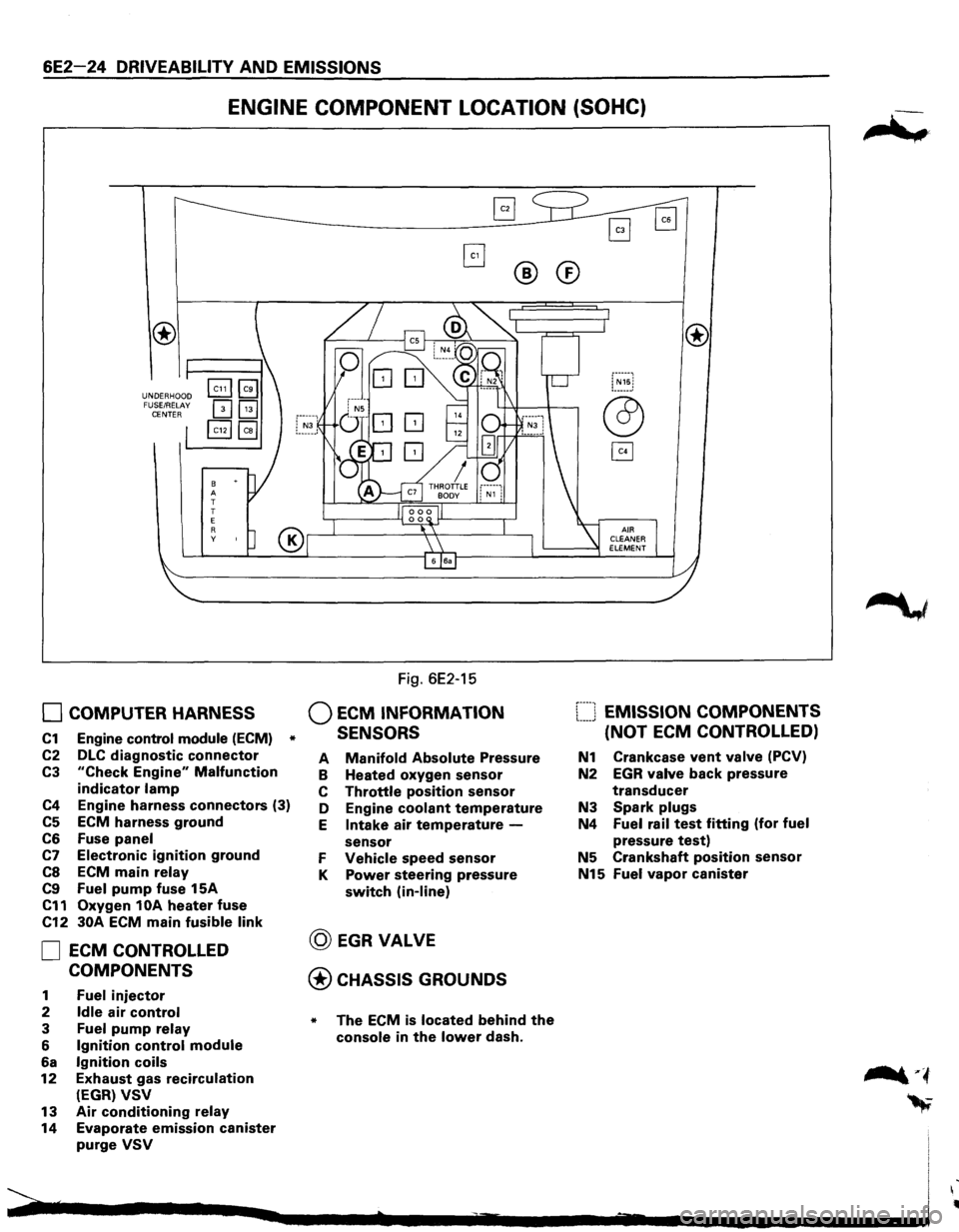
6E2-24 DRIVEABILITY AND EMISSIONS
ENGINE COMPONENT LOCATION (SOHC)
UNDERHOOD
FUSE/RELAY
CENTER
8 A
T
T
E
R y
0 COMPUTER HARNESS
C1 Engine control module (ECM) *
C2 DLC diagnostic connector
C3 "Check Engine" Malfunction
indicator lamp
C4 Engine harness connectors (3)
C5 ECM harness ground
C6 Fuse panel
C7 Electronic ignition ground
CS ECM main relay
C9 Fuel pump fuse 15A
C11 Oxygen 1 OA heater fuse
C12 30A ECM main fusible link
0 ECM CONTROLLED
COMPONENTS
1 Fuel injector
2 Idle air control
3 Fuel pump relay
6 Ignition control module
6a Ignition coils
12 Exhaust gas recirculation
(EGR) VSV
13 Air conditioning relay
14 Evaporate emission canister
purge VSV
Fig. 6E2-15
Q ECM INFORMATION
SENSORS
®
A Manifold Absolute Pressure
B Heated oxygen sensor
C Throttle position sensor
D Engine
coolant temperature
E Intake air temperature -
sensor
F Vehicle speed sensor
K Power steering pressure
switch (in-line)
@ EGRVALVE
@CHASSIS GROUNDS
* The ECM is located behind the
console in the lower dash.
®
[::::J EMISSION COMPONENTS
(NOT
ECM CONTROLLED)
N1 Crankcase vent valve (PCV)
N2 EGR valve back pressure
transducer
N3 Spark plugs
N4 Fuel rail test fitting (for fuel
pressure test)
N5 Crankshaft position sensor
N15 Fuel vapor canister
Page 721 of 1928
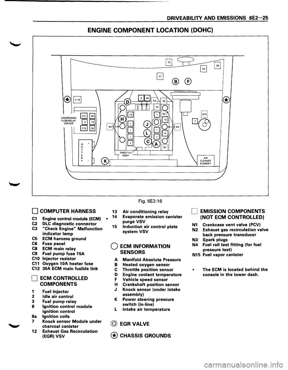
DRIVEABILITY AND EMISSIONS 6E2-25
ENGINE COMPONENT LOCATION (DOHC)
®B
UNDERHOOD FUSE/RELAY CENTER
B A T
T
E
A y
0 COMPUTER HARNESS
C1 Engine control module (ECM)
C2 DLC diagnostic connector
C3 "Check Engine" Malfunction
indicator lamp
C5 ECM harness ground
C6 Fuse panel
C8 ECM main relay
C9 Fuel pump fuse 15A
C10 Injector resistor
C11 Oxygen 1 OA heater fuse
C12
30A ECM main fusible link
0 ECM CONTROLLED
COMPONENTS
1 Fuel injector
2 Idle air control
3 Fuel pump relay
6 Ignition control module
ignition control
6a Ignition coils
7 Knock sensor Module under
charcoal canister
12
Exhaust Gas Recirculation
(EGR) VSV
*
®®
Fig. 6E2-16
13 Air conditioning relay
14 Evaporate emission canister
purge VSV
15 Induction air control plate
system VSV
Q ECM INFORMATION
SENSORS
A Manifold Absolute Pressure
B Heated oxygen sensor
c Throttle position sensor
D Engine
coolant temperature
F Vehicle speed sensor
H Crankshaft
position sensor
J Knock sensor
(under intake
assembly)
K Power steering pressure
switch (in-line)
L Intake air temperature
@ EGRVALVE
@ CHASSIS GROUNDS
f----1 EMISSION COMPONENTS !.-----' (NOT ECM CONTROLLED)
N1 Crankcase vent valve (PCV)
N2 Exhaust gas
recirculation valve
back pressure transducer
N3 Spark plugs
N4 Fuel rail test fitting (for fuel
pressure test)
N15 Fuel vapor canister
* The ECM is located behind the
console in the lower dash.
Page 729 of 1928
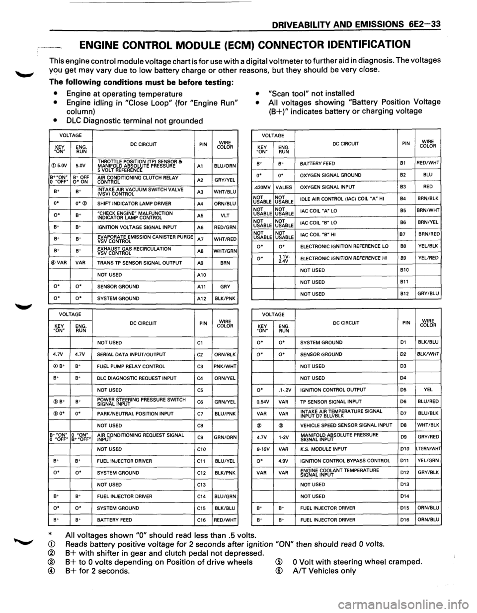
DRIVEABILITY AND EMISSIONS 6E2-33
ENGINE CONTROL MODULE (ECM) CONNECTOR IDENTIFICATION
This engine control module voltage chart is for use with a digital voltmeter to further aid in diagnosis. The voltages
you get may vary due to low battery charge or other reasons, but they should be very close.
The following conditions must be before testing:
• Engine at operating temperature • "Scan tool" not installed
•
Engine idling in "Close Loop" (for "Engine Run"
column) •
All voltages showing "Battery Position Voltage
(8+)" indicates battery or charging voltage
•
DLC Diagnostic terminal not grounded
VOLTAGE VOLTAGE
DC CIRCUIT PIN WIRE
KEY ENG. COLOR
"ON" RUN
DC CIRCUIT PIN WIRE
KEY ENG. COLOR "ON" RUN
ID 5.0V 5.0V THROTILE
POSITION ~TP~ SENSOR & MANIFOLD ABSOLUT P ESSURE A1 BLU/ORN 8+ B+ BATIERY FEED B1 RED/WHT
5 VOLT REFERENCE B+"ON" B+ OFF AIR CONDITIONING CLUTCH RELAY A2 GRY/YEL 0 "OFF" 0* ON
CONTROL o• o• OXYGEN SIGNAL GROUND 82 BLU
B+ s+ INTAKE
AIR VACUUM SWITCH VALVE A3 WHT/BLU (VSV) CONTROL
o• O*® SHIFT INDICATOR LAMP DRIVER A4 ORN/BLU .430MV
VALlES OXYGEN
SIGNAL INPUT
B3 RED
NOT NOT
IDLE AIR CONTROL (lAC) COIL "A" HI B4 8RN/BLK USABLE
USABLE
o• B+ "CHECK ENGINE" MALFUNCTION A5 VLT INDICATOR LAMP CONTROL
B+ B+ IGNITION VOLTAGE SIGNAL INPUT
AS RED/GRN
NOT NOT
lAC COIL "A" LO B5 8RN/WHT USABLE USABLE
NOT NOT
lAC COIL
"B" LO B6 BRN/YEL USABLE
USABLE
B+ B+ EVAPORATE EMISSION CANISTER PURGE A7 WHT/RED VSVCONTROL NOT
NOT
lAC COIL "B" HI B7 BRN/RED USABLE
USABLE
B+ 8~ EXHAUST GAS RECIRCULATION AS WHT/GRN VSV CONTROL
@VAR VAR TRANS TP SENSOR SIGNAL OUTPUT A9 8RN
o• o• ELECTRONIC IGNITION REFERENCE LO 88 YEL/BLK
o• 1.1V-ELECTRONIC
IGNITION REFERENCE HI B9 YEL/RED
2.4V
NOT USED B10
NOT USED
A10
NOT USED
B11 o• o• SENSOR GROUND A11 GRY
NOT USED B12 GRY/BLU o• o• SYSTEM
GROUND A12 8LK/PNK
VOLTAGE
VOLTAGE
DC CIRCUIT PIN WIRE
KEY ENG. COLOR DC CIRCUIT PIN WIRE
KEY ENG. COLOR "ON" RUN "ON" RUN
NOT USED C1 o• o• SYSTEM GROUND D1 BLK/BLU
4.7V 4.7V
SERIAL DATA INPUT/OUTPUT C2 ORN/8LK o• 0* SENSOR GROUND D2 BLK/WHT
@) B+ B+ FUEL PUMP RELAY CONTROL C3 PNK/WHT NOT USED D3
B+ B+ DLC DIAGNOSTIC REQUEST INPUT C4 ORN/YEL NOT USED D4
NOT USED C5 o• .1·.2V IGNITION
CONTROL OUTPUT D5 YEL
@B+ B+ POWER STEERING PRESSURE SWITCH C6 GRN/YEL SIGNAL INPUT 0.54V VAR
TP SENSOR
SIGNAL INPUT D6 BLU/RED
@O* o• PARK/NEUTRAL POSITION
INPUT C7 BLU/PNK VAR
VAR INTAKE AIR TEMPERATURE SIGNAL D7 BLU/BLK INPUT D7 BLU/BLK
NOT USED CB ® ® VEHICLE SPEED SENSOR
SIGNAL INPUT D8 WHT/BLK
B+"ON" 0 "ON" AIR CONDITIONING REQUEST SIGNAL C9 GRN/ORN
0 "OFF" B+"OFF"
INPUT 4.7V 1-2V MANIFOLD ABSOLUTE PRESSURE D9 GRY/RED SIGNAL
INPUT
NOT USED
C10 8-10V
VAR K.S.
MODULE INPUT D10 LTGRN/WHT
B+ B+ FUEL INJECTOR
DRIVER C11 BLU/YEL o• 4.9V IGNITION CONTROL BYPASS CONTROL D11 YELIGRN
o• o• SYSTEM GROUND
C12 BLK/PNK VAR VAR ENGINE COOLANT TEMPERATURE
D12 GRY/BLK SIGNAL
INPUT
NOT USED
C13 NOT USED D13
B+ 8+
FUEL INJECTOR DRIVER C14 BLU/GRN NOT USED D14
o• o• SYSTEM GROUND
C15 BLK/BLU B+ B+ FUEL INJECTOR DRIVER D15 ORN/BLU
8+ B+ BATIERY FEED C16 RED/WHT B+ 8+
FUEL INJECTOR DRIVER D16 ORN/8LU
* All voltages shown "0" should read less than .5 volts.
Reads battery positive voltage for 2 seconds after ignition "ON" then should read 0 volts. CD
®
® @
B+ with shifter in gear and clutch pedal not depressed.
B+ to 0 volts depending on Position of drive wheels
B+ for 2 seconds.
@
®
0 Volt with steering wheel cramped.
A/T Vehicles only
Page 787 of 1928
FUEL SYSTEM
• CHECK:
• CHECK:
• CHECK:
• CHECK:
• CHECK:
• CHECK:
Fuel pump relay operation-pump should
turn "ON" for 2 seconds when ignition is
turned
"ON". Use CHART A-5.
Fuel injectors are correct for the vehicle.
Fuel
pressure, use CHART A-7.
Contaminated
fuel.
Engine fuse (visual inspect).
A
faulty in-tank fuel pump check valve will
allow
the fuel in the lines to drain back to
the tank after engine is stopped. To check
for this condition, perform fuel system
diagnosis CHART A-7.
IGNITION SYSTEM
• CHECK: For proper ignition voltage output with
spark tester J26792 or equivalent (ST-
125).
DRIVEABILITY AND EMISSIONS 6E2-91
• CHECK: Spark plugs. Remove spark plugs, check
for wet plugs, cracks, wear, improper
gap, burned electrodes, or heavy
deposits. Repair
or replace as necessary.
• CHECK: Bare or shorted wires.
• CHECK: Loose ignition coil ground.
ADDITIONAL CHECKS
• CHECK: Idle air control operation-use CHART C-
2C.
• CHECK: Basic engine problem. Refer to ENGINE
MECHANICAL DIAGNOSIS (SECTION
6A).
• CHECK: Service Bulletins for calibration updates.
SURGES AND/OR CHUGGLES
Definition: Engine power variation under steady
throttle or cruise. Feels like the car speeds
up and
slows down with no change in the
acceleration pedal.
PRELIMINARY CHECKS
• Perform the careful visual checks as described at
start
of "Symptoms," Section "6E2-B."
•
Be sure driver understands transmission
operation, and air conditioning compressor
operation
as explained in the owner's manual.
SENSORS
• CHECK: Heated oxygen sensor (H02S). The
H02S should respond quickly to different
throttle position, if it does not, check the
H02S for silicon or other contaminations
from fuel, or use of improper RTV sealant.
The sensor may have a white, powdery
coating and result in a high but false
signal voltage
(rich heated H02S signal
indication). The engine control module
will
then reduce the amount of fuel
delivered
to the engine, causing a severe
driveability problem. Also, watch for
green glycol contamination or cracking.
FUEL SYSTEM
• NOTICE: To determine ifthe condition is caused by
a rich
or lean system, the car should be
driven at the speed of the complaint.
Monitoring block learn will help identify a
problem.
Lean -Block learn above 142. Refer to
"Diagnostic Aids" on facing page of
diagnostic trouble code 44.
Rich -L.T. Fuel Trim above 118. Refer to
"Diagnostic Aids" on facing page of
diagnostic trouble code 45.
• CHECK: Fuel pressure while condition exists. Use
CHART A-7.
• CHECK: In-line fuel filter. Replace if dirty or
plugged.
IGNITION SYSTEM
• CHECK: For proper ignition voltage output using
spark tester (ST-125) J26792
or
equivalent .
• CHECK: Spark plugs. Remove spark plugs, check
for wet plugs, cracks, wear, improper
gap, burned electrodes, or heavy
deposits. Repair
or replace as necessary.
Also, check condition of electronic
ignition and spark plug wires.
• CHECK: Ignition timing. Using "Scan tool".
ADDITIONAL CHECKS
• CHECK: Engine control module grounds for being
clean, tight and in their proper location.
• CHECK: Vacuum lines for kinks or leaks.
• CHECK: Exhaust gas recirculation -There should
be no exhaust gas recirculation at idle.
Refer to CHART C-7.
• CHECK: Generator output voltage. Repair if less
than 9 or more than 16 volts.
Page 791 of 1928
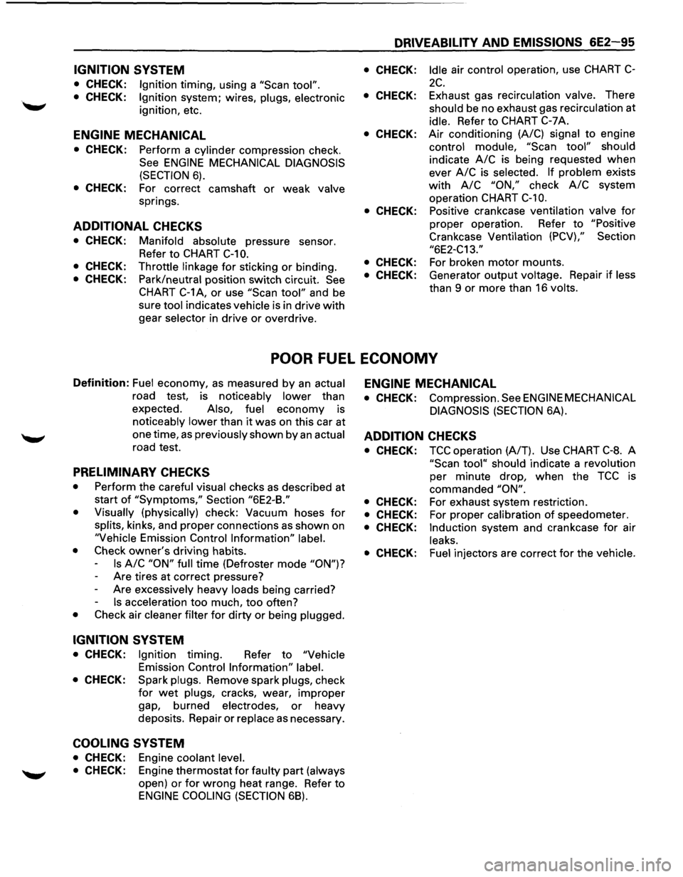
IGNITION SYSTEM
• CHECK: Ignition timing, using a "Scan tool".
• CHECK: Ignition system; wires, plugs, electronic
ignition, etc.
ENGINE MECHANICAL
• CHECK: Perform a cylinder compression check.
See ENGINE MECHANICAL DIAGNOSIS
(SECTION 6).
• CHECK: For correct camshaft or weak valve
springs.
ADDITIONAL CHECKS
• CHECK: Manifold absolute pressure sensor.
Refer to
CHART C-10.
• CHECK: Throttle linkage for sticking or binding.
• CHECK: Park/neutral position switch circuit. See
CHART C-1A,
or use "Scan tool" and be
sure
tool indicates vehicle is in drive with
gear selector in drive or overdrive.
DRIVEABILITY AND EMISSIONS 6E2-95
• CHECK:
• CHECK:
• CHECK:
• CHECK:
• CHECK:
• CHECK:
Idle air control operation, use CHART C-
2C.
Exhaust gas recirculation valve. There
should be no exhaust gas recirculation at
idle. Refer to CHART C-7A.
Air conditioning (A/C) signal to engine
control module, "Scan tool" should
indicate A/C is being requested when
ever
A/C is selected. If problem exists
with A/C "ON," check A/C system
operation
CHART C-10.
Positive crankcase ventilation valve for
proper operation. Refer to "Positive
Crankcase Ventilation (PCV),"
Section
"6E2-C13."
For broken motor mounts.
Generator output
voltage. Repair if less
than 9 or more than 16 volts.
POOR FUEL ECONOMY
Definition: Fuel economy, as measured by an actual
road test, is noticeably lower than
expected.
Also, fuel economy is
noticeably lower than it was on this car at
one time,
as previously shown by an actual
road test.
PRELIMINARY CHECKS
• Perform the careful visual checks as described at
start
of "Symptoms," Section "6E2-B."
• Visually (physically)
check: Vacuum hoses for
splits, kinks, and proper connections as shown on
"Vehicle Emission Control Information" label.
• Check
owner's driving habits.
Is A/C "ON" full time (Defroster mode "ON")?
Are tires at correct pressure?
Are
excessively heavy loads being carried?
Is acceleration too much, too often?
• Check air cleaner filter for dirty or being plugged.
IGNITION SYSTEM
• CHECK: Ignition timing. Refer to "Vehicle
Emission Control Information" label.
• CHECK: Spark plugs. Remove spark plugs, check
for wet plugs, cracks, wear, improper
gap, burned electrodes, or heavy
deposits. Repair or
replace as necessary.
COOLING SYSTEM
• CHECK: Engine coolant level.
• CHECK: Engine thermostat for faulty part (always
open) or for wrong heat range. Refer to
ENGINE COOLING (SECTION 68).
ENGINE MECHANICAL
• CHECK: Compression. See ENGINE MECHANICAL
DIAGNOSIS
(SECTION 6A).
ADDITION CHECKS
• CHECK:
• CHECK:
• CHECK:
• CHECK:
• CHECK:
TCC operation (A/T). Use CHART C-8. A
"Scan tool" should indicate a revolution
per minute drop, when the TCC is
commanded
"ON".
For exhaust system restriction.
For proper
calibration of speedometer.
Induction system and crankcase for air
leaks.
Fuel
injectors are correct for the vehicle.
Page 795 of 1928
DRIVEABILITV AND EMISSIONS 6E2-99
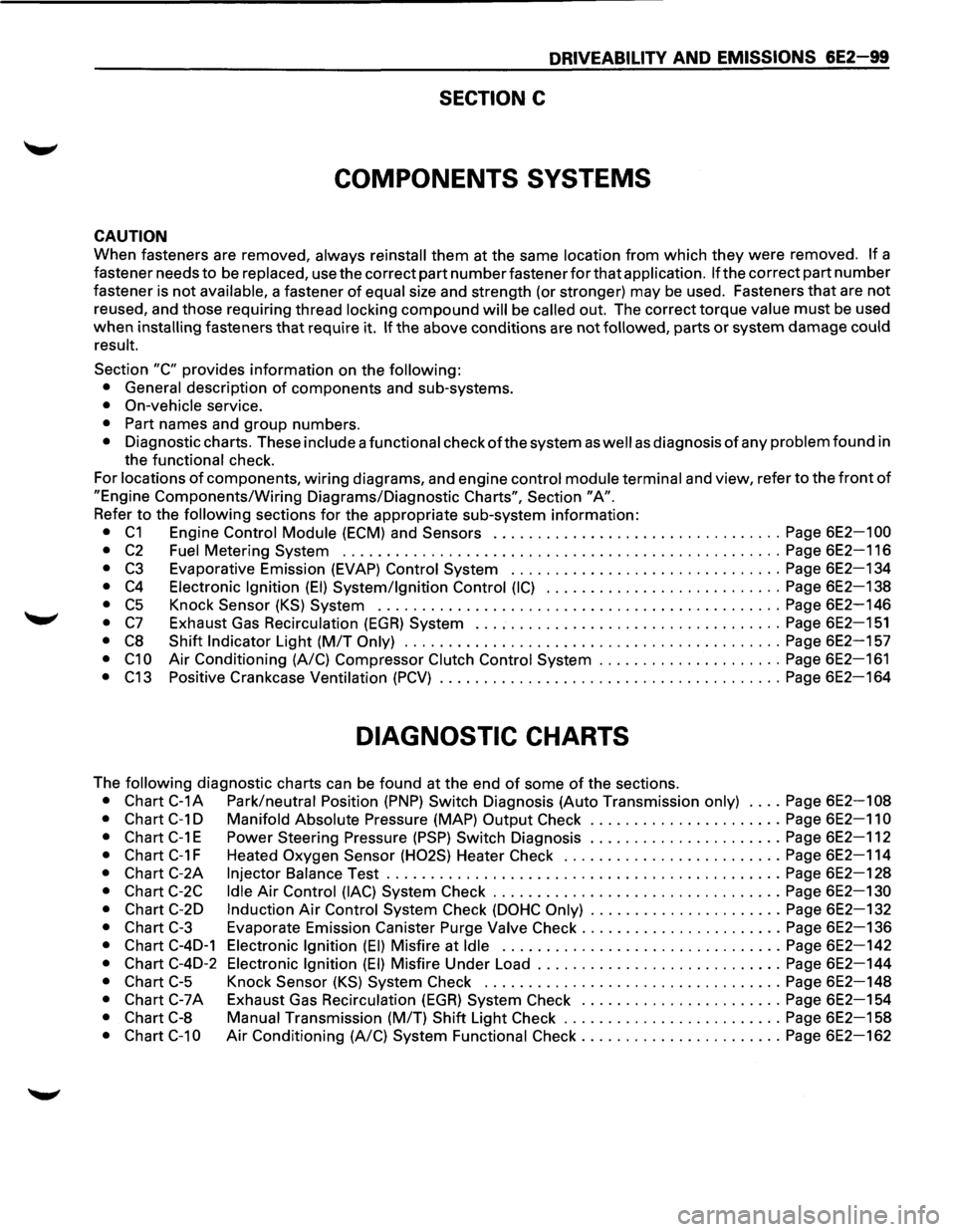
SECTION C
COMPONENTS SYSTEMS
CAUTION
When fasteners are removed, always reinstall them at the same location from which they were removed. If a
fastener needs
to be replaced, use the correct part number fastener for that application. If the correct part number
fastener is not available, a fastener of equal size and strength (or stronger) may be used. Fasteners that are not
reused, and those requiring thread locking compound will be called out. The correct torque value must be used
when installing fasteners that require it. If the above conditions are not followed, parts or system damage could
result.
Section
"C" provides information on the following:
• General description of components and sub-systems.
• On-vehicle service.
• Part names and group numbers.
• Diagnostic charts. These include a functional check of the system as well as diagnosis of any problem found in
the functional check.
For locations
of components, wiring diagrams, and engine control module terminal and view, refer to the front of
"Engine Components/Wiring Diagrams/Diagnostic Charts", Section "A".
Refer to the following sections for the appropriate sub-system information:
• C1 Engine Control Module (ECM) and Sensors ................................. Page 6E2-1 00
•
C2 Fuel Metering System .................................................. Page 6E2-116
• C3 Evaporative Emission (EVAP) Control System ............................... Page 6E2-134
• C4 Electronic Ignition (EI) System/Ignition Control (IC) ........................... Page 6E2-138
• C5 Knock Sensor (KS) System .............................................. Page 6E2-146
• C7 Exhaust Gas Recirculation (EGR) System ................................... Page 6E2-151
• C8 Shift Indicator Light (M/T Only) ........................................... Page 6E2-157
• C1 0 Air Conditioning (A/C) Compressor Clutch Control System ..................... Page 6E2-161
• C13 Positive Crankcase Ventilation (PCV) ....................................... Page 6E2-164
DIAGNOSTIC CHARTS
The following diagnostic charts can be found at the end of some of the sections.
• Chart C-1A Park/neutral Position (PNP) Switch Diagnosis (Auto Transmission only) .... Page 6E2-108
• Chart C-1 D Manifold Absolute Pressure (MAP) Output Check ...................... Page 6E2-11 0
•
Chart C-1 E Power Steering Pressure (PSP) Switch Diagnosis ...................... Page 6E2-112
• Chart C-1 F Heated Oxygen Sensor (H02S) Heater Check ......................... Page 6E2-114
• Chart C-2A Injector Balance Test ............................................. Page 6E2-128
• Chart C-2C Idle Air Control (lAC) System Check ................................. Page 6E2-130
• Chart C-2D Induction Air Control System Check (DOHC Only) ...................... Page 6E2-132
• Chart C-3 Evaporate Emission Canister Purge Valve Check ....................... Page 6E2-136
• Chart C-4D-1 Electronic Ignition (EI) Misfire at Idle ................................ Page 6E2-142
• Chart C-4D-2 Electronic Ignition (EI) Misfire Under Load ............................ Page 6E2-144
• Chart C-5 Knock Sensor (KS) System Check .................................. Page 6E2-148
• Chart C-7A Exhaust Gas Recirculation (EGR) System Check ....................... Page 6E2-154
• Chart C-8 Manual Transmission (MIT) Shift Light Check ......................... Page 6E2-158
• Chart C-1 0 Air Conditioning (A/C) System Functional Check ....................... Page 6E2-162