brake sensor ISUZU TROOPER 1995 Owners Manual
[x] Cancel search | Manufacturer: ISUZU, Model Year: 1995, Model line: TROOPER, Model: ISUZU TROOPER 1995Pages: 1928
Page 1593 of 1928
-------------------
CRUISE CONTROL 98-9
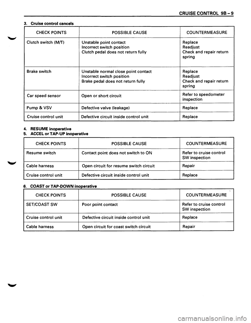
3. Cruise control cancels
CHECK POINTS POSSIBLE CAUSE COUNTERMEASURE
Clutch switch
(M/T) Unstable point contact Replace
Incorrect
switch position Readjust
Clutch
pedal does not return fully Check and repair return
spring
Brake switch
Unstable normal close point contact Replace
Incorrect
switch position Readjust
Brake
pedal does not return fully Check and repair return
spring
Car speed sensor
Open or short circuit Refer to speedometer
inspection
Pump& VSV Defective valve (leakage) Replace
Cruise control unit Defective circuit inside control unit Replace
4. RESUME inoperative
5. ACCEL or TAP-UP inoperative
CHECK POINTS POSSIBLE CAUSE COUNTERMEASURE
Resume switch
Contact
point does not switch to ON Refer to cruise control
SW
inspection
Cable harness Open circuit for resume switch circuit Repair
Cruise
control unit Defective circuit inside control unit Replace
6 COAST or TAP-DOWN inoperative ,,
CHECK POINTS POSSIBLE CAUSE COUNTERMEASURE
SET/COAST
SW Poor point contact Refer to cruise control
SW
inspection
Cruise
control unit Defective circuit inside control unit Replace
Cable
harness Open circuit for coast switch circuit Repair
Page 1617 of 1928
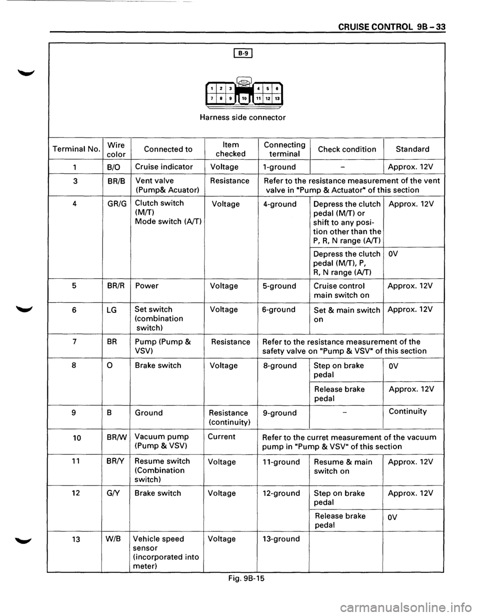
CRUISE CONTROL 98-33
[IT]
G?J 1 2 3 iiiill 4 5 8
7 8 9 10.n 11 12 13
Harness side connector
Terminal No. Wire
Connected to Item Connecting
Check condition Standard
color checked terminal
1 B/0 Cruise
indicator Voltage 1-ground -Approx. 12V
3 BR/B Vent valve
Resistance Refer to the resistance measurement of the vent
(Pump& Acuator)
valve in "Pump & Actuator• of this section
4
GR/G Clutch switch
Voltage 4-ground Depress the clutch Approx. 12V
(M/T) pedal (M/T)
or
Mode switch (AfT) shift to any posi-
tion other than the
P, R, N range (A/T)
Depress the clutch
ov
pedal (M/T), P,
R, N range (AfT)
5 BR/R Power
Voltage 5-ground Cruise control Approx.
12V
main switch on
6 LG Set switch Voltage 6-ground Set & main switch Approx.
12V
(combination on
switch)
7
BR Pump (Pump &
Resistance Refer to the resistance measurement of the
VSV) safety valve on "Pump & VSV" of this section
8
0 Brake switch Voltage 8-ground Step on brake ov
pedal
Release brake Approx.
12V
pedal
9 B Ground Resistance 9-ground
-Continuity
(continuity)
10 BR/W Vacuum pump Current
Refer to the curret measurement of the vacuum
(Pump &
VSV) pump in "Pump & VSV" of this section
11 BR!Y Resume switch
Voltage 11-ground Resume & main Approx.
12V
(Combination switch on
switch)
12 G/Y Brake
switch
Voltage 12-ground Step on brake Approx.
12V
pedal
Release brake ov
pedal
13 W/B Vehicle speed Voltage 13-ground
sensor (incorporated
into
meter)
Fig. 9B-15
Page 1788 of 1928
10-30 BODY
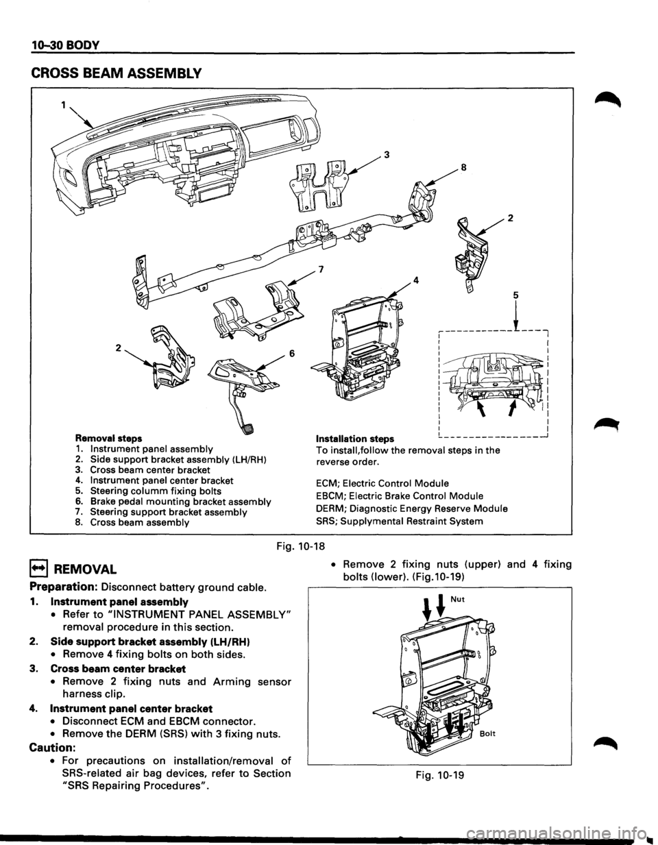
CROSS BEAM ASSEMBLY
2 6
Removal steps 1. Instrument panel assembly 2. Side support bracket assembly (LH/RH)
3. Cross beam center bracket 4. Instrument panel center bracket 5. Steering columm fixing bolts
6. Brake pedal mounting bracket assembly 7. Steering support bracket assembly 8. Cross beam assembly
3
4
Installation steps
8 2
5
, -----------L_l
I I
I
I I
~~~~~®~! II I I I I !._ ___ ---------___ _J
To install, follow the removal steps in the
reverse order.
ECM; Electric Control Module
EBCM; Electric Brake Control Module
DERM; Diagnostic Energy Reserve Module
SRS; Supplymental Restraint System
Fig. 10-18
E) REMOVAL
Preparation: Disconnect battery ground cable.
1. Instrument panel assembly
• Refer to "INSTRUMENT PANEL ASSEMBLY"
removal procedure in this section.
2.
Side support bracket assembly (LH/RH)
• Remove 4 fixing bolts on both sides.
3. Cross beam
center bracket
• Remove 2 fixing nuts and Arming sensor
harness clip.
4. Instrument panel center bracket
• Disconnect ECM and EBCM connector.
• Remove the DERM (SRS) with 3 fixing nuts.
Caution:
• For precautions on installation/removal of
SRS-related air bag devices, refer to Section
"SRS Repairing Procedures". •
Remove
2 fixing nuts (upper) and 4 fixing
bolts (lower). (Fig.10-19)
Fig. 10-19