brake sensor ISUZU TROOPER 1995 Repair Manual
[x] Cancel search | Manufacturer: ISUZU, Model Year: 1995, Model line: TROOPER, Model: ISUZU TROOPER 1995Pages: 1928
Page 486 of 1928
if.. ~ ' -
5A4-76 4-WHEEL ANTILOCK BRAKE SYSTEM (ABS)
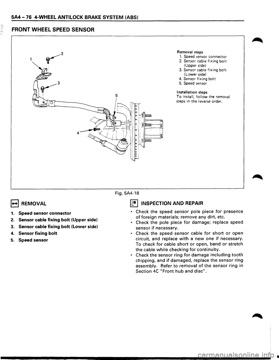
FRONT WHEEL SPEED SENSOR
1••1 REMOVAL
1. Speed sensor connector
2. Sensor cable fixing bolt (Upper side)
3. Sensor cable fixing bolt (Lower side)
4. Sensor fixing bolt
5. Speed sensor
5
Removal steps
1. Speed sensor connector 2. Sensor cable fixing bolt (Upper side)
3.
Sensor cable fixing bolt (Lower side)
4. Sensor fixing bolt 5. Speed sensor
Installation steps
To install, follow the removal
steps in the reverse order.
Fig. 5A4-18
IL•IINSPECTION AND REPAIR
• Check the speed sensor pole piece for presence
of foreign materials; remove any dirt, etc.
• Check the pole piece for damage; replace speed
sensor
if necessary.
• Check the speed sensor cable for short or open
circuit, and replace
with a new one if necessary.
To check
for cable short or open, bend or stretch
the
cable while checking for continuity.
• Check the sensor ring for damage including tooth
chipping, and if damaged, replace the sensor ring
assembly. Refer
to removal of the sensor ring in
Section
4C "Front hub and disc".
•
Page 487 of 1928
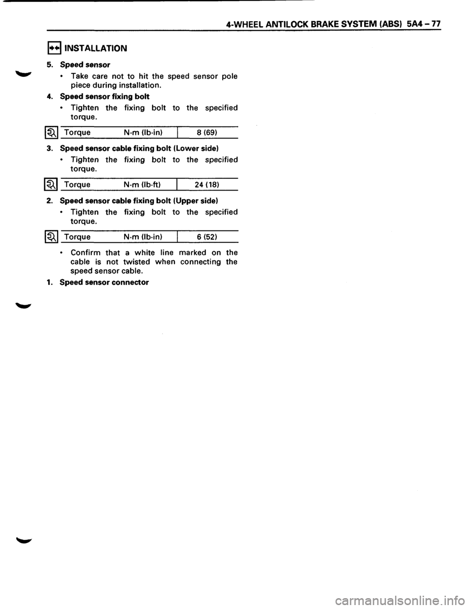
I••! INSTALLATION
5. Speed sensor
4-WHEEL ANTILOCK BRAKE SYSTEM (ABS) 5A4-77
,.....,. • Take care not to hit the speed sensor pole
piece during installation.
4. Speed sensor fixing bolt
• Tighten the fixing bolt to the specified
torque.
1~1 Torque N·m (lb·in) 8 (69)
3. Speed sensor cable fixing bolt (lower side)
• Tighten the fixing bolt to the specified
torque.
~~~ Torque N·m (lb-ft) 24 (18)
2. Speed sensor cable fixing bolt (Upper side)
• Tighten
torque.
1~1 Torque the
fixing
bolt to the specified
N-m (lb·in) 6 (52)
• Confirm that a white line marked on the
cable is not twisted when connecting the
speed sensor
cable.
1. Speed sensor connector
Page 488 of 1928
5A4-78 4-WHEEL ANTILOCK BRAKE SYSTEM (ABS)
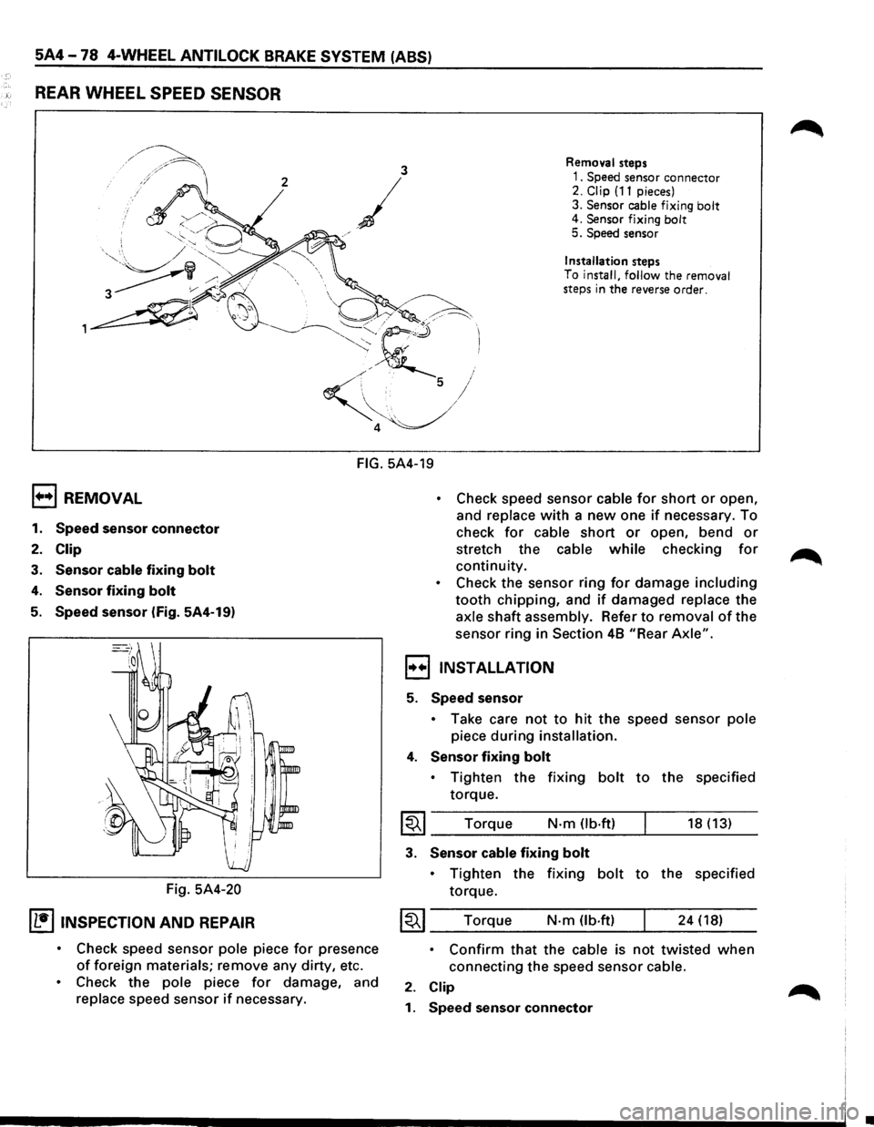
REAR WHEEL SPEED SENSOR
3 Removal steps
2
/
1. Speed sensor connector 2. Clip (11 pieces)
3.
Sensor cable fixing bolt 4. Sensor fixing bolt 5. Speed sensor
j
/
Installation steps
To
install, follow the removal
steps in the reverse order.
FIG. 5A4-19
1+•1 REMOVAL
1. Speed sensor connector
2. Clip
3. Sensor cable fixing bolt
4. Sensor fixing bolt
5. Speed sensor (Fig. 5A4-19)
Fig.
5A4-20
IL•ItNSPECTION AND REPAIR
• Check speed sensor pole piece for presence
of foreign materials; remove any dirty, etc.
• Check the pole piece for damage, and
replace speed sensor if necessary.
• Check speed sensor cable for short or open,
and
replace with a new one if necessary. To
check
for cable short or open, bend or
stretch the cable while checking for
continuity.
• Check the sensor ring for damage including
tooth chipping, and if damaged replace the
axle shaft assembly. Refer to removal of the
sensor ring in
Section 48 "Rear Axle".
,,..,,INSTALLATION
5. Speed sensor
• Take care not to hit the speed sensor pole
piece during installation.
4. Sensor fixing bolt
• Tighten the fixing bolt to the specified
torque.
I~I ____ T_o_rq~u_e ____ N __ ·m __ O_b·_ft_) __ ~ ____ 18_(_1_3_) __
3. Sensor cable fixing bolt
• Tighten the fixing bolt to the specified
torque.
~~~ Torque N·m (lb.ft) 24 (18)
• Confirm that the cable is not twisted when
connecting the speed sensor cable.
2. Clip
1. Speed sensor connector
•
Page 507 of 1928
ENGINE DIAGNOSIS 6-9
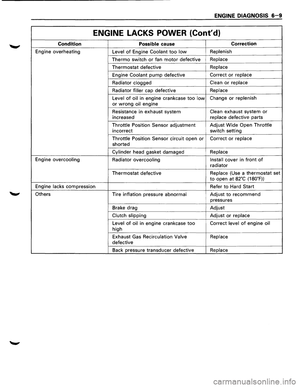
ENGINE LACKS POWER (Cont'd)
Condition Possible cause Correction
Engine overheating
Level of Engine Coolant too low Replenish
Thermo switch or fan motor defective Replace
Thermostat defective Replace
Engine
Coolant pump defective Correct or replace
Radiator clogged
Clean or replace
Radiator
filler cap defective Replace
Level
of oil in engine crankcase too low Change or replenish
or
wrong oil engine
Resistance in exhaust system
Clean exhaust system or
increased replace
defective parts
Throttle Position Sensor adjustment Adjust
Wide Open Throttle
incorrect switch setting
Throttle Position Sensor circuit open
or Correct or replace
shorted
Cylinder head gasket damaged Replace
Engine overcooling
Radiator
overcooling Install cover
in front of
radiator
Thermostat defective Replace
(Use a thermostat set
to open at a2·c (180.F))
Engine
lacks compression Refer to Hard Start
Others Tire inflation pressure
abnormal Adjust to recommend
pressures
Brake drag Adjust
Clutch slipping Adjust or replace
Level
of oil in engine crankcase too Correct level of engine oil
high
Exhaust Gas
Recirculation Valve Replace
defective
Back pressure transducer defective
Replace
Page 874 of 1928
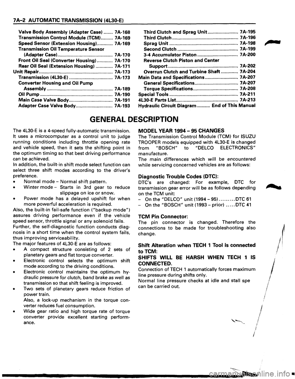
7A-2 AUTOMATIC TRANSMISSION (4L30-E)
Valve Body Assembly (Adapter Case) ....... 7A-168 Third Clutch and Sprag Unit ....................... 7A-195
Transmission Control
Module (TCM) ......... 7A-169 Third Clutch .................................................. 7A-196
Speed Sensor (Extension Housing) ............ 7A-169 Sprag
Unit ....................................................
7A-198
Transmission
Oil Temperature Sensor Second
Clutch .............................................. 7A-199
(Adapter Case) ..........................................
7A-170 3-4 Accumulator Piston ............................... 7A-200
Front Oil Seal (Converter Housing) ............ 7A-170 Reverse Clutch Piston and Center
Rear
Oil Seal (Extension Housing) ............. 7A-171 Support ..................................................... 7 A-202
Unit Repair ........................................................ 7A-173 Overrun Clutch and Turbine Shaft ............. 7A-204
Transmission (4L30-E) ................................. 7A-173 Main Data and Specifications ......................... 7 A-207
Converter Housing and Oil Pump General
Specifications ................................. 7 A-207
Assembly .................................................. 7 A-189 Torque
Specifications .................................. 7A-208
Oil
Pump ....................................................... 7A-190 Special Tools .................................................... 7A-211
Main Case Valve Body ................................. 7A-191 4L30-E Parts List.. ............................................. 7A-213
Adapter Case Valve Body ............................ 7A-193 Hydraulic
Circuit Diagram .......... End of This Manual
GENERAL DESCRIPTION
The 4L30-E is a 4-speed fully-automatic transmission.
It uses a microcomputer as a control unit to judge
running conditions
including throttle opening rate
and vehicle speed, then
it sets the shifting point in
the
optimum timing so that best driving performance
can be achieved.
In addition, the built-in shift mode select function can
select three shift modes according to the driver's
preference.
• Normal mode-Normal shift pattern.
• Winter mode-Starts in 3rd gear to reduce
slippage on ice
or snow.
• Power mode has a delayed upshift for when
more powerful acceleration is required.
Also, the built-in fail-safe
function ("backup mode")
assures driving performance even if the vehicle
speed sensor,
throttle signal or any solenoid fails.
Further, the self-diagnostic
function conducts diag
nosis in a short time when the control system fails,
thus improving serviceability.
The major features of 4L30-E are as follows:
• A compact structure consisting of 2 sets of
planetary gears and flat torque converter.
• Electronic control selects the optimum shift
mode according
to the driving conditions.
• Electronic control maintains the optimum hy
draulic pressure for clutch, band brake as well as
transmission so that shift feeling is improved.
• Two sets of planetary gears reduce friction of
power train.
Also, a lock-up mechanism in the torque con
verter reduces fuel consumption.
• Wide gear ratio and high torque rate of torque
converter provide
excellent starting perform
ance.
MODEL YEAR 1994-95 CHANGES
The Transmission Control Module (TCM) for ISUZU
TROOPER
models equipped with 4L30-E is changed
from "BOSCH" to "DELCO ELECTRONICS"
manufacture.
The main differences
which will be encountered
while servicing concerned vehicles are as follows:
Diagnostic Trouble Codes (DTC):
DTC's are changed: For example, DTC for
transmission gear error will be as follows depending
on the TCM unit:
-
On the "DELCO" unit (1994-95) ......... DTC 61
-On the "BOSCH" unit (1993-prior) ..... DTC 41
TCM Pin Connector:
The pin connector is changed. Therefore the
connections
to be made for troubleshooting also
change.
Shift Alteration when TECH 1 Tool is connected
toTCM:
SHIFTS WILL BE HARSH WHEN TECH 1 IS
CONNECTED.
Connection of TECH 1 automatically forces maximum
line pressure during shifts only.
Normal line pressure checks at idle and stall spe
can be carried out.
/
/
I J I
/
l
•
Page 876 of 1928
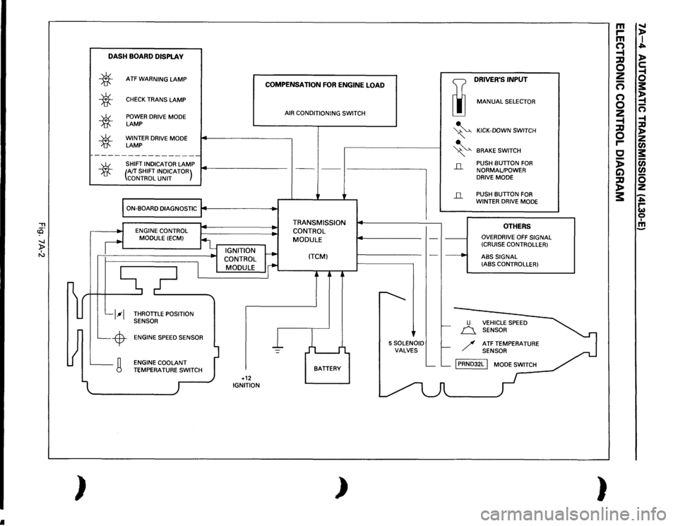
•
"'Tl c3' -..J )> I "'
~ )
DASH
BOARD
DISPLA
V
*
*
*
*
ATF
WARNING
LAMP
CHECK
TRANS
LAMP
POWER DRIVE MODE LAMP WINTER DRIVE MODE LAMP
~----------------
SHIFT INDICATOR
LAMP
COMPENSATION
FOR
ENGINE
LOAD
AIR CONDITIONING SWITCH
TI
DRIVER'S
INPUT
liJ
MANUAL
SELECTOR
~
KICK-DOWN SWITCH
" ~
BRAKE
SWITCH
*
(AfT
SHIFT INDICATOR)
CONTROL
UNIT
---
' ---
I-------------,
il
PUSH BUTTON
FOR
NORMALJPOWER
DRIVE MODE
ON-BOARD DIAGNOSTIC
j4
.. ,
..
l__l--1 L_-$-L_g
ENGINE CONTROL
MODULE
(ECM)
_ IGNITION
CONTROL
I
MODULE
i
THROTTLE POSITION
SENSOR
ENGINE SPEED SENSOR
l
I
I -
ENGINE COOLANT TEMPERATU~,_.TCH
)
I +12 IGNITION
• •
TRANSMISSION
CONTROL MODULE
(TCM)
j
L I
BATTERY
)
--
~
'
5SOLENOID VALVES
il
-·----·
___.
u
PUSH BUTTON
FOR
WINTER DRIVE MODE
OTHERS
OVERDRIVE
OFF
SIGNAL
(CRUISE CONTROLLER)
ABS
SIGNAL
(ABS CONTROLLER)
f.-
n_
VEHICLE SPEED
SENSOR
f-
/
ATF TEMPERATURE SENSOR
L__ L__
[PRNDJ2L
I MODE SWITCH
-
m
.....
r-
)>
m
I
(")
..;=...
-t
)>
;::g 0
c:
2
-1
-
0
(")
s:
(")
~
0
-
2
n
-t
-1
;::g
:a
0
)> z
r-
en
c
s:
:;
(i)
C)
en
~
0 z
3:
-..;=... r-w 0 I !!!
)
Page 877 of 1928
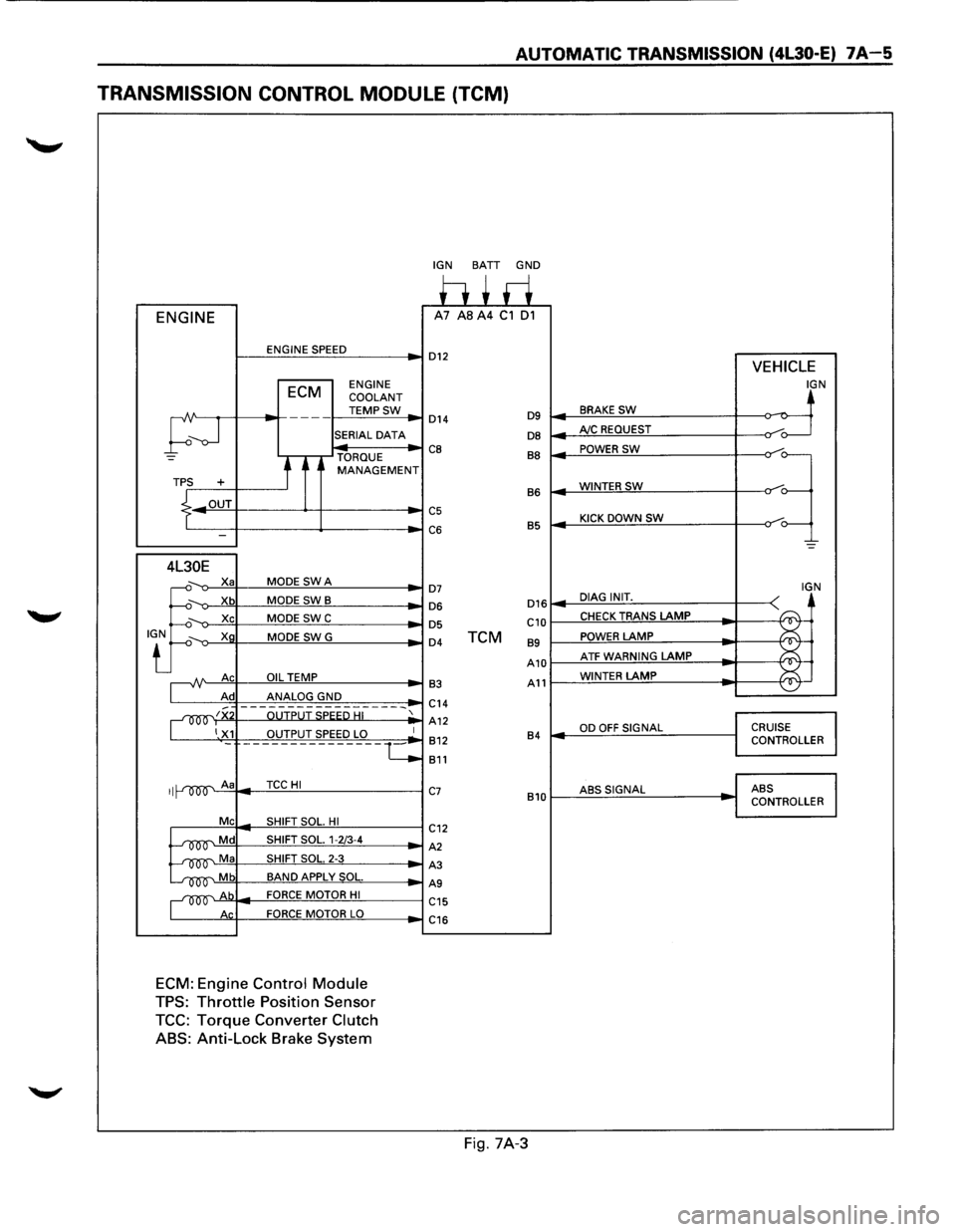
AUTOMATIC TRANSMISSION (4l30-E) 7A-5
TRANSMISSION CONTROL MODULE (TCM)
ENGINE
ENGINE SPEED
ECM ENGINE
COOLANT
TEMPSW
;--J
---
SERIAL DATA
TORQUE
t MANAGEMENT TPS +
.L OUT
I -
4L30E
.J:
X a MODE SWA
Xb MODE SWB
Xc MODE SWC
Xg MODE SWG
A Ac OIL TEMP
Ad ANALOG GND
~~x OUTPUT SPEED HI
1 X1 OUTPUT SPEED LO
II A a TCCHI
Me SHIFT SOL. HI
~Md SHIFT SOL. 1-2/3-4
~Ma SHIFT SOL. 2-3
~Mb BAND APPLY SOL.
~Ab FORCE MOTOR HI
Ac FORCE MOTOR LO
ECM: Engine Control Module
TPS: Throttle Position Sensor
TCC: Torque Converter Clutch
ABS:
Anti-Lock Brake System
-
1
·-c
IGN BATT GND
h+ri A7 AS A4 C1 01
D12 VEHICLE
IGN
BRAKE SW ~ D14 D9 ~
DB AJC REQUEST /o---
CB BB POWER SW
=~
WINTERSW B6
C5 KICK DOWN SW C6 B5
-=
D7 IGN
D16 DIAG INIT. D6
~
D5 C10 CHECK TRANS LAMP
D4 TCM 89 POWER LAMP
A10 ATF WARNING LAMP ~
¥ 83 A11 WINTER LAMP
C14
A12
OD OFF SIGNAL CRUISE 812 84 CONTROLLER
811
C7 ABSSIGNAL ABS
810 CONTROLLER
C12
A2
A3
AS
C15
C16
Fig. 7A-3
Page 883 of 1928

AUTOMATIC TRANSMISSION (4L30-E) 7 A-11
FUNCTIONS OF INPUT /OUTPUT COMPONENTS
Components Function
Speed sensor
Senses rotation
of output shaft and feeds the data to Transmission
(fixed
to transmission (T/M)) Control Module (TCM)
Throttle Senses the extent of throttle valve opening and the speed of the throttle
position sensor (TPS) valve lever motion to open the valve and feeds the data to TCM (fed to
(fixed to engine)
Engine Control Module (ECM) also)
I
Brake Switch (SW) Senses whether the driver has pressed the brake pedal or not and feeds
N (fixed
to brake pedal) the
information to TCM
p Kick-down SW (fixed to Senses whether the driver has pushed the accelerator pedal fully or not
u accelerator pedal) and feeds the information to TCM
T Mode
SW (fixed to T/M) Senses the select lever position and feeds the information to TCM
s Power drive SW Senses whether the driver has selected the power mode and feeds the
I (fixed to front console) information to TCM
G T/M
oil temp. sensor
Senses the T/M oil temperature and feeds the data to TCM
N Engine
coolant Senses the engine cooling water temperature and feeds the data to TCM
A temperature
SW (feeds the signal from ECM)
L
Engine speed
signal Feeds the signals monitoring engine speed to TCM from Ignition Control
Module
(fed to ECM also)
Air conditioning Senses whether the air conditioner has been switched on or not and
information feeds the information
to TCM
On-board diagnostic
input By monitoring the Ground (GND), the location of failure is shown on the
T/M
monitor lamp ("CHECK TRANS") by flashing the diagnostic trouble
code
Winter switch
Senses whether the driver has selected the winter mode, and feeds the
(fixed
to front console) information to TCM
Cruise
controller Downshift takes place when Overdrive OFF signal is received from auto
(Overdrive
OFF signal) cruise control unit
Shift
solenoid Selects shift point and gear position suited to the vehicle running con-s 1-2/3-4, 2-3
dition on the basis of TCM output 0 Band apply solenoid
Controls oil flow suited to the vehicle running condition on the basis of L
E TCM output
0 N
Torque
Converter Controls clutch engagement/disengagement suited to the vehicle
u 0 Clutch solenoid running condition on the basis of TCM output
T I Force motor Adjusts the oil pump delivery pressure to line pressure suited to the p D
(Pressure regulator vehicle running condition on the basis of TCM output u valve) T
Power drive mode lamp
Informs the driver whether the vehicle is in power mode or not
s Winter drive mode lamp Informs the driver whether the vehicle is in winter mode or not
I T/M monitor lamp Informs the driver of failure in the system. It also displays the self diagnosis
G
("CHECK TRANS") code.
N Data Link Connector
(DLC) When connected with TECH 1 or tester, can communicate the data for A
L function
check, etc. (fed to ECM also). When TECH 1 is not connected, can
communicate the
signal for torque management with ECM.
Self-diagnosis connector
When short-circuited with the bipolar connector, the T/M monitor lamp
displays
a failure by code.
ATF warning
lamp Lights when ATF oil temperature rises.
ABS signal When the select lever is at "Reverse" or "L" range, sends a signal to the
ABS controller as one of the ABS control conditions.
Page 939 of 1928
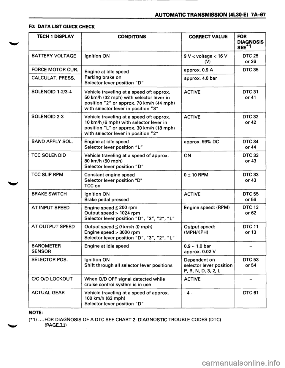
AUTOMATIC TRANSMISSION (4L30-E) 7 A~7
FO: DATA LIST QUICK CHECK
TECH 1
DISPLAY
CONDITONS CORRECT VALUE
BATIERY VOLTAGE
Ignition ON 9 V < voltage < 16 V
(V)
FORCE MOTOR CUR. Engine at idle speed approx. 0.9 A
CALCULAT. PRESS. Parking
brake on
approx. 4.0 bar Selector lever position "D"
SOLENOID 1-2/3-4
Vehicle traveling at a speed of: approx. ACTIVE
50 km/h (32 mph) with selector lever in
position
"2" or approx. 70 km/h (44 mph)
with selector lever in position "3"
SOLENOID 2-3
Vehicle traveling at a speed of: approx. ACTIVE
10 km/h_(6 mph) with selector lever in
position
"L" or approx. 30 km/h (18 mph)
with selector lever in position "2"
BAND APPLY SOL. Engine at idle speed
approx. 99% DC
Selector lever position "L"
TCC SOLENOID Vehicle traveling at a speed of approx. ON
80 km/h (50 mph)
Selector lever position "D"
TCC SLIP RPM Constant engine speed 0 ± 10 RPM
Selector lever position "D"
TCCon
BRAKE SWITCH
Ignition ON ACTIVE
Brake pedal pressed
AT
INPUT SPEED Engine speed :;:; 200 rpm Engine speed: (RPM)
Output speed> 1024 rpm
Selector lever position "D", "3", "2", "L"
AT OUTPUT SPEED Output speed:;:; 0 km/h (0 mph) Output speed:
Engine speed >
3000 rpm (MPH/KPH)
Selector lever position "D", "3", "2", "L" ·
BAROMETER
Engine at idle speed 0.9-1.0 bar
SENSOR approx. 0.02 V
SELECTOR POS. Ignition ON Dependent on
Shift through all selector lever positions selector lever position
P, R, N, D, 3, 2, L
C!C OlD LOCKOUT When 0/D OFF signal detected while ACTIVE
cruise control system is in use
ACTUAL GEAR Vehicle traveling at a speed of approx. - 4 -
100 km/h (62 mph)
Selector lever position
"D"
NOTE:
(*1) .... FOR DIAGNOSIS OF A DTC SEE CHART 2: DIAGNOSTIC TROUBLE CODES (DTC)
tPAGE..ll)
FOR
DIAGNOSIS
SEE*1
DTC25
or 26
DTC35
DTC 31
or 41
DTC32
or 42
DTC34
or 44
DTC33
or 43
DTC33
or 43
DTC55
or 56
DTC 13
or 62
DTC 11
or13
-
DTC53
or 54
-
DTC 61
Page 943 of 1928
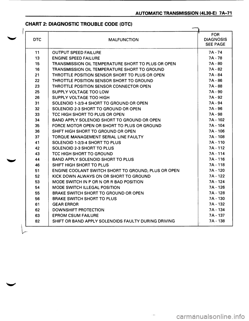
AUTOMATIC TRANSMISSION (4L30-E) 7 A-71
CHART 2: DIAGNOSTIC TROUBLE CODE (OTC)
I v
' FOR
DTC MALFUNCTION DIAGNOSIS
SEE PAGE
11 OUTPUT
SPEED FAILURE 7A -74
13 ENGINE SPEED FAILURE 7A -78
15 TRANSMISSION OIL TEMPERATURE SHORT TO PLUS OR OPEN 7A-80
16 TRANSMISSION OIL TEMPERATURE SHORT TO GROUND 7A-82
21 THROTTLE POSITION SENSOR SHORT TO PLUS OR OPEN 7A-84
22 THROTTLE POSITION SENSOR SHORT TO GROUND 7A-86
23 THROTTLE
POSITION SENSOR CONNECTOR OPEN 7A-88
25
SUPPLY VOLTAGE TOO LOW 7A-90
26 SUPPLY VOLTAGE TOO HIGH 7A-92
31 SOLENOID 1-2/3-4 SHORT TO GROUND OR OPEN 7A-94
32
SOLENOID 2-3 SHORT TO GROUND OR OPEN 7A-96
33 TCC
HIGH SHORT TO PLUS OR OPEN 7A-98
34
BAND APPLY SOLENOID SHORT TO GROUND OR OPEN 7A-102
35 FORCE MOTOR OPEN OR SHORT TO PLUS OR GROUND 7A-104
36 SHIFT HIGH SHORT TO GROUND OR OPEN 7A-106
37 TORQUE MANAGEMENT SERIAL LINE FAULTY 7A-108
41 SOLENOID 1-2/3-4 SHORT TO PLUS 7A-110
42 SOLENOID 2-3 SHORT TO PLUS 7A-112
43 TCC HIGH SHORT TO GROUND 7A-114
44
BAND APPLY SOLENOID SHORT TO PLUS 7A-116
46 SHIFT HIGH SHORT TO PLUS 7A-118
51 ENGINE COOLANT SWITCH SHORT TO GROUND, PLUS OR OPEN 7A-120
52 KICK DOWN ALWAYS ON OR SHORT TO GROUND 7A-122
53 MODE SWITCH IN P OR N OR R BAD POSITION 7A-124
54
MODE SWITCH ILLEGAL POSITION 7A-126
55 BRAKE
SWITCH SHORT TO GROUND OR OPEN 7A-128
56 BRAKE
SWITCH
SHORT TO PLUS 7A-130
61 GEAR ERROR 7A-132
62 DOWNSHIFT PROTECTION 7A-134
63
EPROM CSUM FAILURE 7A-137
82 SHIFT OR BAND APPLY SOLENOIDS FAULTY DURING DRIVING 7A-138