ISUZU TROOPER 1995 Workshop Manual
Manufacturer: ISUZU, Model Year: 1995, Model line: TROOPER, Model: ISUZU TROOPER 1995Pages: 1928
Page 1251 of 1928
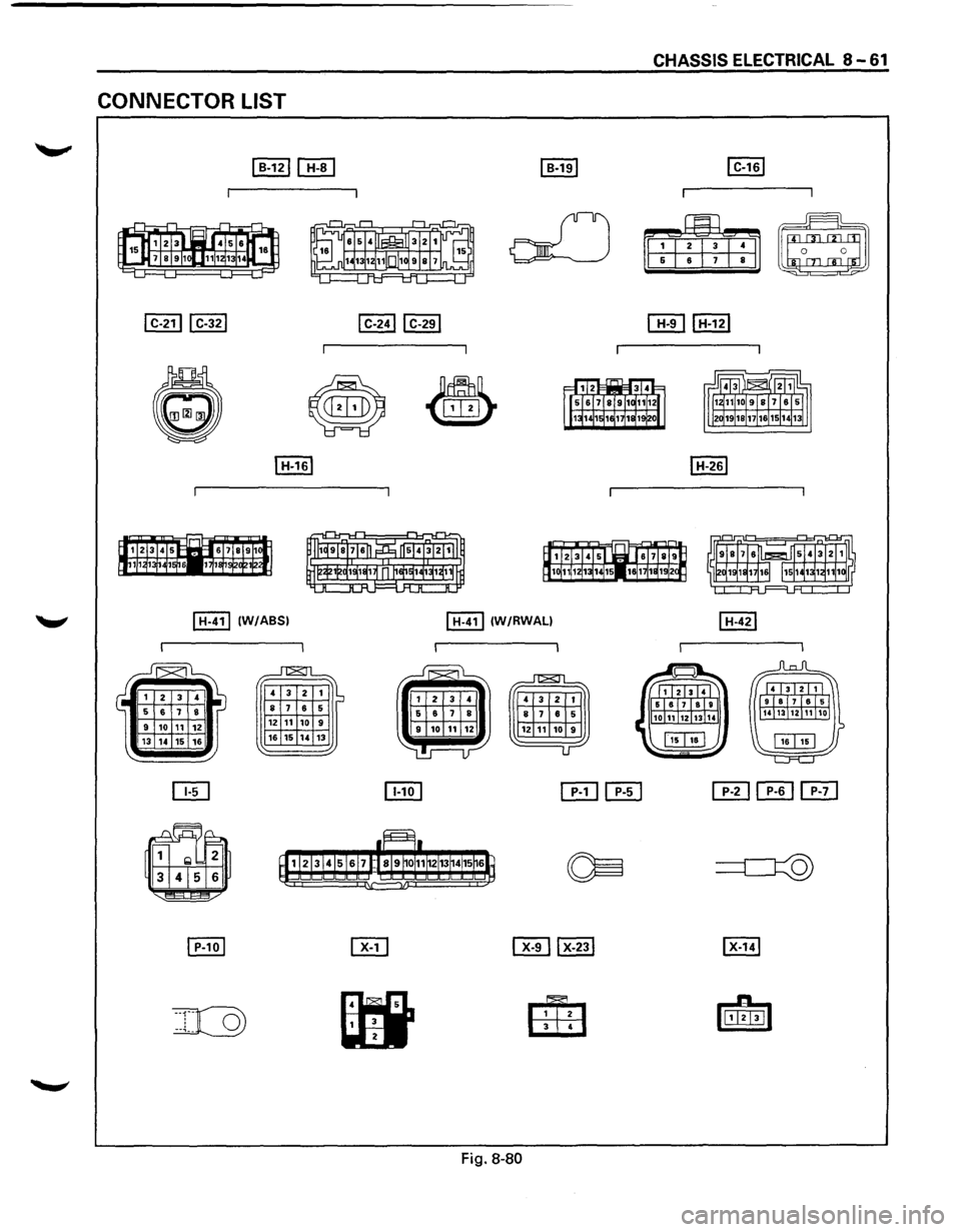
CHASSIS ELECTRICAL 8-61
CONNECTOR LIST
I H-41l (W/ABSI I H-41l (W/RWALI
~
4 3
2 1 ~ 8 7 6 5
12 11 10 9
16 15 14 13
Fig. 8-80
Page 1252 of 1928
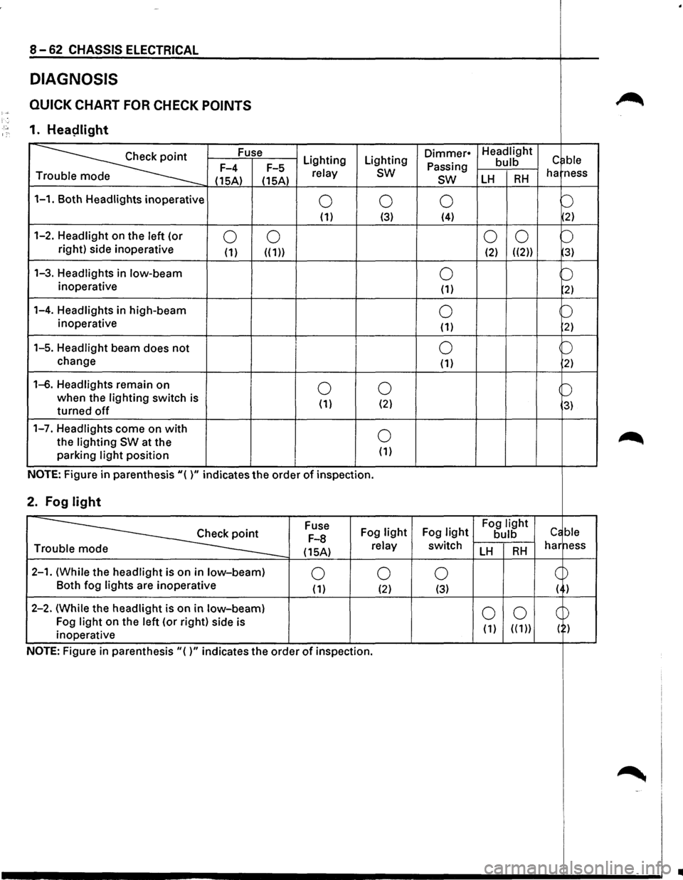
8-62 CHASSIS ELECTRICAL
DIAGNOSIS
QUICK CHART FOR CHECK POINTS ~ )-; '. ·'·• 1. Heaplight 1:·
~
Fuse Lighting Lighting Dimmer• Headlight c ~ble Passing bulb F-4
F-5 relay sw ha ness
T
(15A) (15A) sw LH RH
1-1. Both Headlights inoperative 0 0 0 b (1) (3) (4) 2)
1-2. Headlight on
the left (or 0 0 0
0 b right) side inoperative (1) ((1)) (2) ((2)) 3)
1-3. Headlights in low-beam 0 b inoperative (1) 2)
1-4. Headlights in high-beam 0 b inoperative
(1) 2)
1-5. Headlight beam does not 0 p
change (1) 2)
1-6. Headlights remain on 0 0 b when the lighting switch is
( 1) (2) 3) turned off
1-7. Headlights come on with 0 ~ the lighting SW at the
parking light position (1)
NOTE: Figure in parenthesis"( )" indicates the order of inspection.
2. Fog light
~
Fuse
Fog light Fog light Fog light Cc ble F-8 bulb
(15A) relay switch LH RH har ness Tr
2-1. (While the headlight is on in low-beam) 0 0 0 c ~ Both
fog lights are inoperative (1) (2) (3) ( )
2-2. (While the headlight is
on in low-beam) 0 0 CD Fog light on the left (or right) side is
( 1) ( ( 1)) ( ) inoperative
NOTE: Figure
in parenthesis"()" indicates the order of inspection.
~ -'
..
Page 1253 of 1928
![ISUZU TROOPER 1995 Workshop Manual CHASSIS ELECTRICAL 8-63
1-1. BOTH HEADLIGHTS INOPERATIVE
• IS THE LIGHTING RELAY NORMAL? I
I
I I
YES I NO I
I
I
• IS [[I[] GROUNDED SECURELY? I REPLACE THE LIGHTING RELAY I
I
I
I
YES](/img/61/57183/w960_57183-1252.png "ISUZU TROOPER 1995 Workshop Manual CHASSIS ELECTRICAL 8-63
1-1. BOTH HEADLIGHTS INOPERATIVE
• IS THE LIGHTING RELAY NORMAL? I
I
I I
YES I NO I
I
I
• IS [[I[] GROUNDED SECURELY? I REPLACE THE LIGHTING RELAY I
I
I
I
YES")
CHASSIS ELECTRICAL 8-63
1-1. BOTH HEADLIGHTS INOPERATIVE
• IS THE LIGHTING RELAY NORMAL? I
I
I I
YES I NO I
I
I
• IS [[I[] GROUNDED SECURELY? I REPLACE THE LIGHTING RELAY I
I
I
I
YES I NO I
I I
• IS THE DIODE NORMAL? J GROUND IT SECURELY I
I
I I
YES I NO I
I
I
• DISCONNECT THE LIGHTING SW CONNECTOR REPLACE THE DIODE J • IS THE BATTERY VOLTAGE APPLIED BETWEEN THE HARNESS
SIDE CONNECTOR 1 [[I[j AND GROUND?
I
I I
YES I NO I
I I
• REMOVE THE LIGHTING SW REPAIR A POOR CONNECTION AT THE CONNECTORS
• IS THERE CONTINUITY BETWEEN 1 [[I[] AND 7 ~WHEN OR AN OPEN CIRCUIT BETWEEN THE FUSUBLE LINK SETTING THE LIGHTING SWAT THE HEADLIGHT POSITION? FL-1 (80A) AND 1 ~
I
I I
I YES I NO I
1 I
REPAIR A POOR CONNECTION AT THE CONNECTORS OR AN REPAIR OR REPLACE THE LIGHTING SW I OPEN CIRCUIT BETWEEN THE HARNESS SIDE CONNECTOR 1WI] AND~ (GROUND) OF THE LIGHTING SW
Page 1254 of 1928
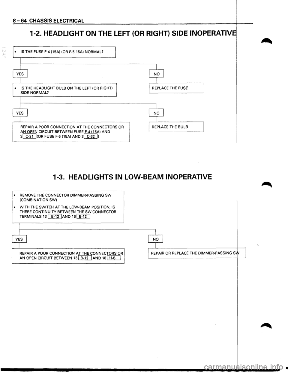
8 -64 CHASSIS ELECTRICAL
1-2. HEADLIGHT ON THE LEFT (OR RIGHT) SIDE INOPERATIVE
• IS THE FUSE F-4 (15A) (OR F-5 15Al NORMAL?
I
I
YES I
I
• IS THE HEADLIGHT BULB ON THE LEFT (OR RIGHT)
SIDE NORMAL?
I
I
YES I
I
I
REPAIR A POOR CONNECTION AT THE CONNECTORS OR
AN OPEN CIRCUIT BETWEEN FUSE F-4 (15Al AND
3~(0R FUSE F-5 115Al AND 3WUI
I
I NO I
I
I REPLACE THE FUSE
I
I NO I
I
I REPLACE THE BULB
I
I
1-3. HEADLIGHTS IN LOW-BEAM INOPERATIVE
• REMOVE THE CONNECTOR DIMMER•PASSING SW (COMBINATION SW)
• WITH
THE SWITCH AT THE LOW-BEAM POSITION, IS THERE CONTINUITY BETWEEN THE SW CONNECTOR
TERMINALS
13[[I[jAND 16[[1[]
I
I
YES I
I
REPAIR A POOR CONNECTION AT THE CONNECTORS OR
AN OPEN CIRCUIT BETWEEN 13[[ll]AND 10~
I
I NO I
I
I REPAIR OR REPLACE THE DIMMER•PASSING S1tJ I
Page 1255 of 1928
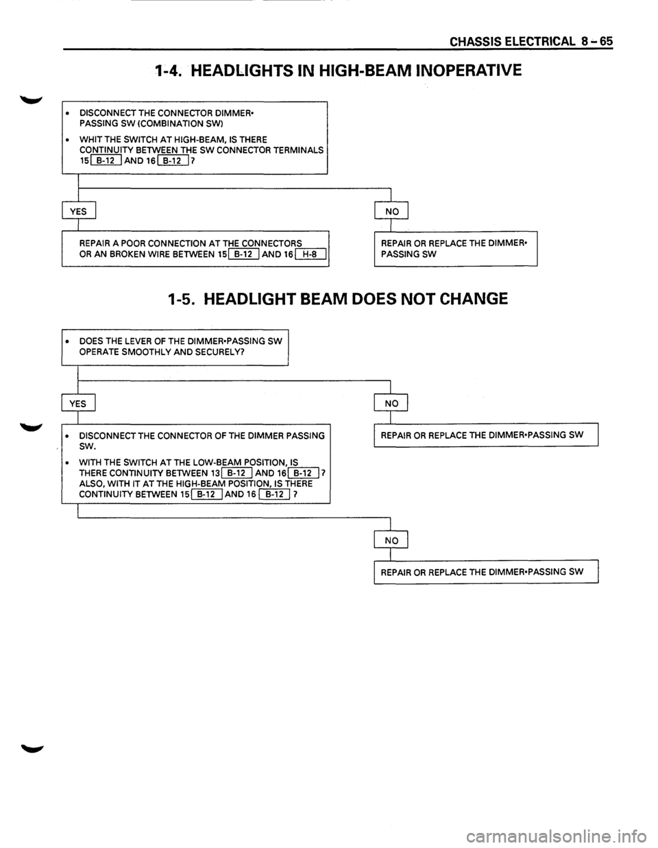
CHASSIS ELECTRICAL 8 .... 65
1-4. HEADLIGHTS IN HIGH-BEAM INOPERATIVE
• DISCONNECT THE CONNECTOR DIMMER•
PASSING SW (COMBINATION SWl
• WHIT THE SWITCH AT HIGH-BEAM, IS THERE
CONTINUITY BETWEEN THE SW CONNECTOR TERMINALS
15~AND16~7
I
I I
YES I NO I
I I
REPAIR A POOR CONNECTION AT THE CONNECTORS REPAIR OR REPLACE THE DIMMER•
OR AN BROKEN WIRE BETWEEN 15[[]IJAND 16[Jf[J PASSING SW
1-5. HEADLIGHT BEAM DOES NOT CHANGE
• DOES THE LEVER OF THE DIMMER•PASSING SW
OPERATE SMOOTHLY AND SECURELY?
I
I I
YES I
I NO I
I I
• DISCONNECT THE CONNECTOR OF THE DIMMER PASSING I REPAIR OR REPLACE THE DIMMER•PASSING sw J sw.
• WITH THE SWITCH AT THE LOW-BEAM POSITION, IS THERE CONTINUITY BETWEEN 13[[g] AND 16(]]U 1 ALSO, WITH IT AT THE HIGH-BEAM POSITION, IS THERE CONTINUITY BETWEEN 15(]]UAND 16 []}[) 1
I
l
I NO I
I
l REPAIR OR REPLACE THE DIMMER•PASSING SW J
Page 1256 of 1928
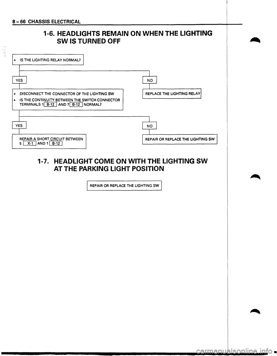
8 -66 CHASSIS ELECTRICAL
•
•
•
1-6. HEADLIGHTS REMAIN ON WHEN THE LIGHTING
SW IS TURNED OFF
IS THE LIGHTING RELAY NORMAL? I
I
I I
YES I I NO J
I I
DISCONNECT THE CONNECTOR OF THE LIGHTING SW I REPLACE THE LIGHTING RELAYI
IS
THE CONTINUITY BETWEEN THE SWITCH CONNECTOR
TERMINALS 1ITI[J AND 7[[ITJ NORMAL?
I
I I
YES I
I NO I
I I I I
REPAIR A SHORT CIRCUIT BETWEEN
5
ITI]AND1~ I REPAIR OR REPLACE THE LIGHTING sw I
1-7. HEADLIGHT COME ON WITH THE LIGHTING SW
AT THE PARKING LIGHT POSITION
I REPAIR OR REPLACE THE LIGHTING sw I
..
Page 1257 of 1928
•
•
•
•
•
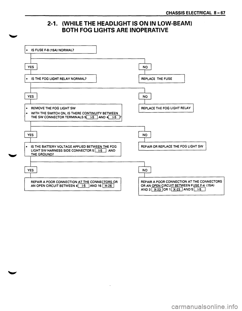
CHASSIS ELECTRICAL 8-67
2-1. (WHILE THE HEADLIGHT IS ON IN LOW-BEAM}
BOTH FOG LIGHTS ARE INOPERATIVE
IS FUSE F-8 (15A) NORMAL? I
I
I I
YES I NO I
I j
IS THE FOG LIGHT RELAY NORMAL? I REPLACE THE FUSE I
I
I j
YES I NO I
I I
REMOVE THE FOG LIGHT SW REPLACE THE FOG LIGHT RELAY I
WITH THE SWITCH ON, IS THERE CONTINUITY BETWEEN
THE SW CONNECTOR TERMINALS sc:::E[J AND 4[}[]7
I
I I
YES I NO j
I J
IS THE BATTERY VOLTAGE APPLIED BETWEEN THE FOG REPAIR OR REPLACE THE FOG LIGHT sw I
LIGHT SW HARNESS SIDE CONNECTOR sill] AND THE GROUND?
I
I I
YES I NO I
I I
REPAIR A POOR CONNECTION AT THE CONNECTORS OR REPAIR A POOR CONNECTION AT THE CONNECTORS
AN OPEN CIRCUIT BETWEEN 4[}[]AND 16 [[ill OR AN OPEN CIRCUIT BETWEEN FUSE F-4 (15AI
AND 31 x-23 loR 1 Wi] AND s DD
Page 1258 of 1928
8-68 CHASSIS ELECTRICAL
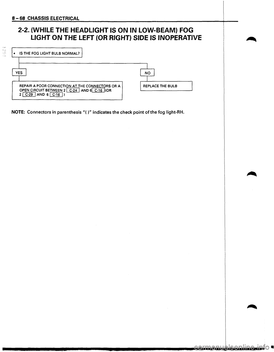
2-2. (WHILE THE HEADLIGHT IS ON IN LOW-BEAM) FOG
LIGHT
ON THE LEFT (OR RIGHT) SIDE IS INOPERATIVE
• IS THE FOG LIGHT BULB NORMAL?
I
I
YES I
I
REPAIR A POOR CONNECTION AT THE CONNECTORS OR A OPEN CIRCUIT BETWEEN 2 WU AND 6~(0R 2~AND 6[f}[]l
I
I NO I
I
l REPLACE THE BULB
NOTE: Connectors in parenthesis"()" indicates the check point of the fog light-RH.
I
•
Page 1259 of 1928
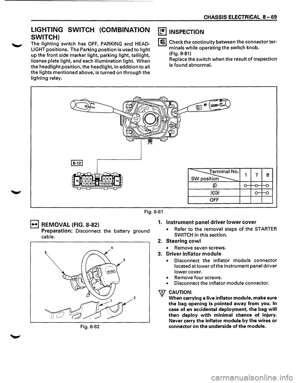
LIGHTING SWITCH (COMBINATION
SWITCH)
The lighting switch has OFF, PARKING and HEAD
LIGHT positions. The Parking position is used to light
up the front side marker light, parking light, taillight,
license
plate light, and each illumination light. When
the headlight position, the headlight, in addition
to all
the lights mentioned above, is turned on through the
lighting relay.
CHASSIS ELECTRICAL 8-69
~ INSPECTION
I til Check the continuity between the connector ter
minals
while operating the switch knob.
(Fig. 8-81)
Replace the switch when the result
of inspection
is found abnormal.
Terminal No.
SW position 1 7 8
~D
OFF
Fig. 8-81
B REMOVAL (FIG. 8-82)
Preparation: Disconnect the battery ground
cable.
4
2
Fig. 8-82 1.
Instrument panel driver lower cover
• Refer to the
removal steps of the STARTER
SWITCH
in this section.
2.
Steering cowl
• Remove seven screws.
3.
Driver inflator module
• Disconnect the inflator module connector
located at lower
oft he instrument panel driver
lower cover.
• Remove four screws.
• Disconnect the inflator module connector.
W CAUTION:
When carrying a live inflator module. make sure
the bag opening is pointed away from you. In
case of an accidental deployment, the bag will
then deploy with minimal chance of injury.
Never carry
the inflator module by the wires or
connector on the underside of the module.
Page 1260 of 1928
I ..
8 -70 CHASSIS ELECTRICAL
When placing a live inflator module on a bench
or other surface, always face the bag and trim
cover up, away from the surface. This is neces
sary so that a free space is provided to allow the
air bag to expand in the unlikely event of acci·
dental
deployment.
4. Steering wheel
• Refer to STEERING WHEEL REPLACEMENT in
Section 3F4.
5. Lighting switch (Combination switch)
• Disconnect the switch connector.
• Remove four screws.
• Remove the lighting switch together with SRS
coil assembly.
'\f CAUTION:
Do not remove SRS coil assembly from the com·
bination switch assembly.
E) INSTALLATION
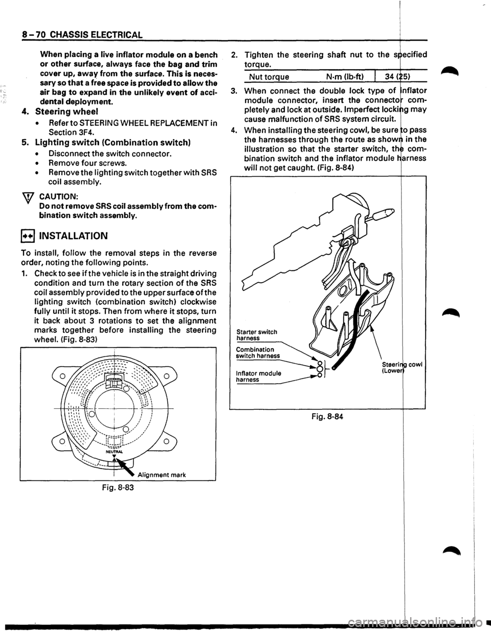
To install, follow the removal steps in the reverse
order, noting the
following points.
1. Check to see if the vehicle is in the straight driving
condition and turn the rotary section of the SRS
coil assembly provided to the upper surface ofthe
lighting switch (combination switch) clockwise
fully until it stops. Then from where it stops, turn
it back about 3 rotations to set the alignment
marks together before installing the steering
wheel. (Fig. 8-83)
Alignment mark
Fig. 8-83
2. Tighten the steering shaft nut to the s ecified
torque.
Nut torque N·m (lb.ft)
3. When connect the double lock type of nflator
module connector, insert the connecto com
pletely
and lock at outside. Imperfect locki g may
cause malfunction of SRS system circuit.
4. When installing the steering cowl, be sure o pass
the harnesses
through the route as show in the
illustration so that the starter switch, th com
bination switch and the inflator module
will not get caught. (Fig. 8-84)
Starter switch
harness
Combination
switch harness
~~ ~
Fig. 8-84
cowl
•