fuse ISUZU TROOPER 1995 Workshop Manual
[x] Cancel search | Manufacturer: ISUZU, Model Year: 1995, Model line: TROOPER, Model: ISUZU TROOPER 1995Pages: 1928
Page 1449 of 1928
CHASSIS ELECTRICAL 8-259
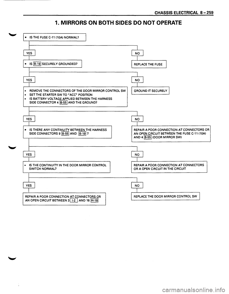
1. MIRRORS ON BOTH SIDES DO NOT OPERATE
• IS THE FUSE C-11 (10AI NORMAL? I
I
YES
I NO I
I
• IS IB-191 SECURELY GROUNDED? I REPLACE THE FUSE I
I
YES
j NO I
I
• REMOVE THE CONNECTORS OF THE DOOR MIRROR CONTROL SW GROUND IT SECURELY I
• SET THE STARTER SW TO "ACC" POSITION
• IS BATTERY VOLTAGE APPLIED BETWEEN THE HARNESS
SIDE
CONNECTOR 4IB-55I AND THE GROUND?
I
YES
j NO I
I
• IS THERE ANY CONTINUITY BETWEEN THE HARNESS REPAIR A POOR CONNECTION AT CONNECTORS OR
SIDE CONNECTORS siB-551 AND IB-191? AN OPEN CIRCUIT BETWEEN THE FUSE C-11 (10AI
AND 4IB-55I (DOOR MIRROR SWI
I
YES
I NO I
I
• IS THE CONTINUITY IN THE DOOR MIRROR CONTROL REPAIR A POOR CONNECTION AT CONNECTORS
SWITCH NORMAL? OR A OPEN CIRCUIT IN THE CIRCUIT
I
YES
I NO I
I
REPAIR
A POOR CONNECTION AT CONNECTORS OR REPLACE THE DOOR MIRROR CONTROL SW I
AN OPEN CIRCUIT BETWEEN 3@] AND 18IH-18I
Page 1451 of 1928
CHASSIS ELECTRICAL 8-261
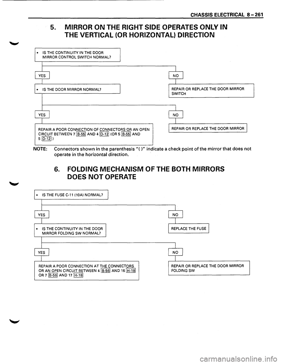
5. MIRROR ON THE RIGHT SIDE OPERATES ONLY IN
THE VERTICAL (OR HORIZONTAL) DIRECTION
• IS THE CONTINUITY IN THE DOOR
MIRROR CONTROL SWITCH NORMAL?
l
YES I NO I
1
• IS THE DOOR MIRROR NORMAL? REPAIR OR REPLACE THE DOOR MIRROR
SWITCH
I
YES
I NO I
1
REPAIR A POOR CONNECTION OF CONNECTORS OR AN OPEN REPAIR OR REPLACE THE DOOR
MIRROR I
CIRCUIT BETWEEN 7IB-55I AND 4ID-12I (OR 5IB-55I AND
5ID-12I l
NOTE: Connectors shown in the parenthesis"( )" indicate a check point of the mirror that does not
operate in the horizontal direction.
•
•
6. FOLDING MECHANISM OF THE BOTH MIRRORS
DOES NOT
OPERATE
IS THE FUSE C-11 (10A) NORMAL? I
I
L I
YES
I NO I
I T
IS THE CONTINUITY IN THE DOOR I MIRROR FOLDING SW NORMAL? REPLACE THE
FUSE l
I
I l
YES j NO l
I I
REPAIR
A POOR CONNECTION AT THE CONNECTORS REPAIR OR REPLACE THE DOOR
MIRROR
OR AN OPEN CIRCUIT BETWEEN 4IB-56I AND 16IH-1BI
OR 7 IB-561 AND 17IH-1BI FOLDING
SW
Page 1452 of 1928
8 -262 CHASSIS ELECTRICAL
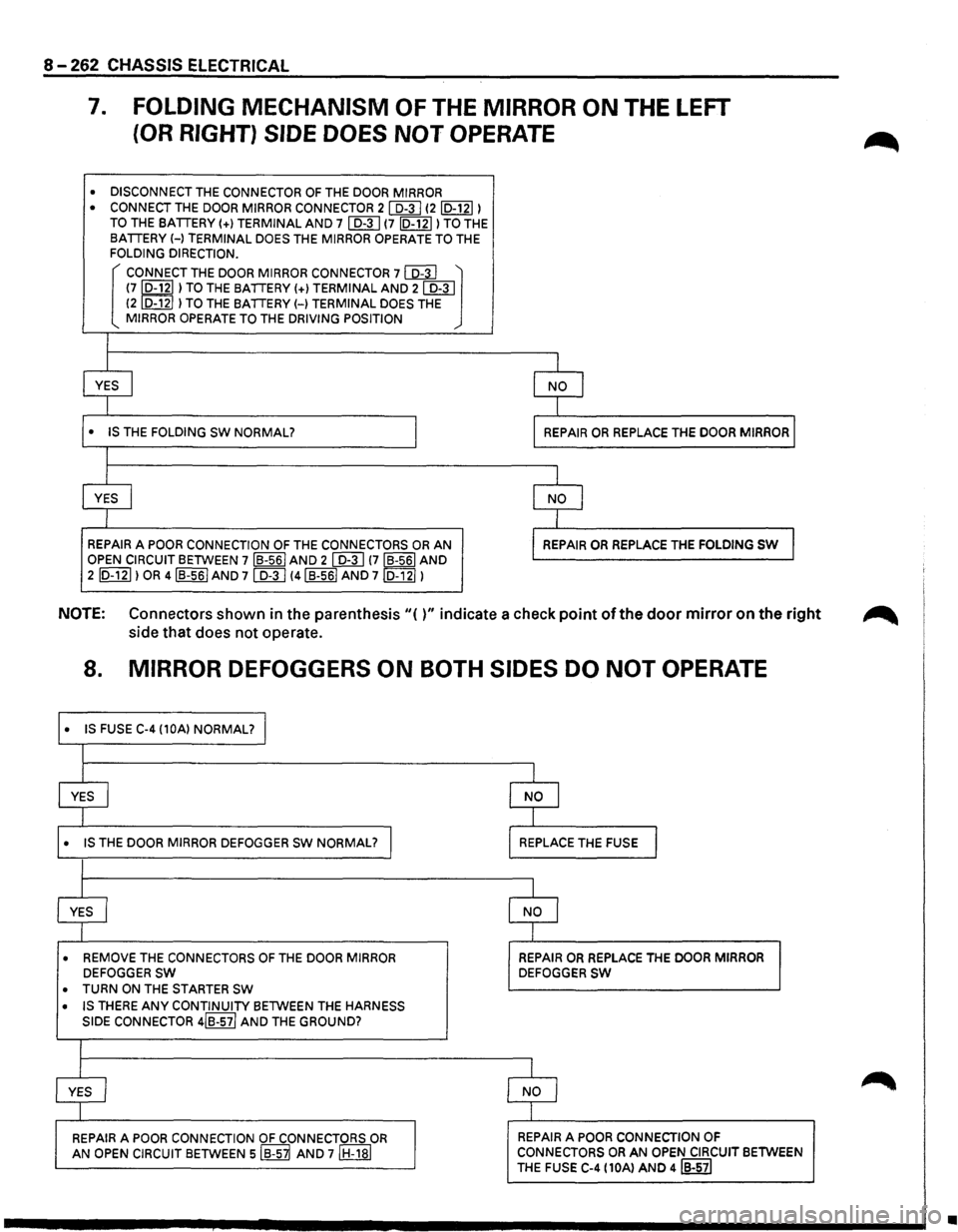
7. FOLDING MECHANISM OF THE MIRROR ON THE LEFT
(OR RIGHT) SIDE DOES NOT OPERATE
• DISCONNECT THE CONNECTOR OF THE DOOR MIRROR
• CONNECT THE DOOR MIRROR CONNECTOR 21 D-31 12ID-12I) TO THE BATTERY(+) TERMINAL AND 7 I D-3 I (7 ID-121) TO THE
BATTERY H TERMINAL DOES THE MIRROR OPERATE TO THE FOLDING DIRECTION.
[ CONNECT THE DOOR MIRROR CONNECTOR 7 co:3J ~ (7,D-121 ) TO THE BATTERY(+) TERMINAL AND 21 D-31 (2 D-12 ) TO THE BATTERY H TERMINAL DOES THE MIRROR OPERATE TO THE DRIVING POSITION
I
I
1
YES I I NO I
I I
• IS THE FOLDING SW NORMAL? I I REPAIR OR REPLACE
THE DOOR MIRROR I
I
I
1
YES I l NO I
I J
REPAIR A POOR CONNECTION OF THE CONNECTORS OR AN l REPAIR OR REPLACE THE FOLDING SW J OPEN CIRCUIT BETWEEN 7 IB-561 AND 2 I D-3 I !7IB-56I AND
2 ID-121) OR 4IB-56I AND 71 D-31 !4IB-56I AND 7ID-12I)
NOTE: Connectors shown in the parenthesis"()" indicate a check point of the door mirror on the right ~
side that does not operate.
8. MIRROR DEFOGGERS ON BOTH SIDES DO NOT OPERATE
• IS FUSE C-4 (10A) NORMAL? J
I
I I
YES
I NO I
I t
• IS THE DOOR MIRROR DEFOGGER sw NORMAL? I REPLACE THE FUSE I
I
l 1
YES I NO I
I I
• REMOVE THE CONNECTORS OF THE DOOR MIRROR REPAIR OR REPLACE THE DOOR MIRROR DEFOGGER SW DEFOGGER SW
• TURN ON THE STARTER SW
• IS THERE ANY CONTINUITY BETWEEN THE HARNESS
SIDE
CONNECTOR 4IB-57/ AND THE GROUND?
I
I
1
YES I NO I
I I
REPAIR A POOR CONNECTION OF CONNECTORS OR REPAIR A POOR CONNECTION OF
AN OPEN CIRCUIT BETWEEN siB-S~ AND 7IH-18I CONNECTORS OR AN OPEN CIRCUIT BETWEEN
THE
FUSE C-4 (10Al AND 4IB-57I
•
Page 1455 of 1928
CHASSIS ELECTRICAL 8-265
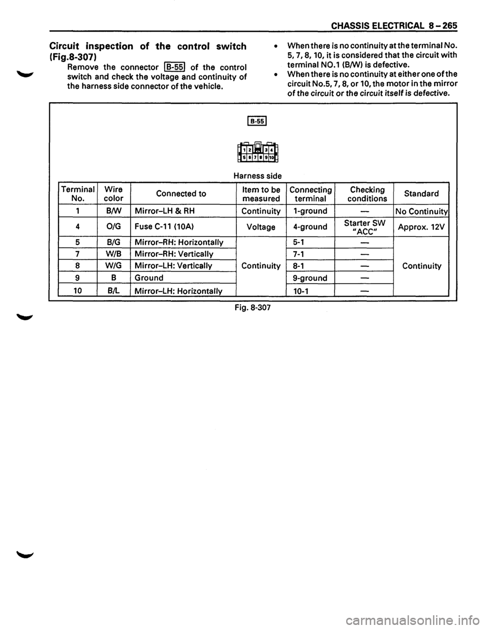
Circuit inspection of the control switch
(Fig.S-307)
Remove the connector I B-55l of the control
switch and check the voltage and continuity of
the harness side connector of the vehicle. •
When
there is no continuity at the terminal No.
5, 7, 8, 10, it is considered that the circuit with
terminal N0.1 (8/W) is defective.
Terminal Wire
Connected to No. color
1 B/W Mirror-LH & RH
4 0/G Fuse C-11 (10A)
5 B/G Mirror-RH: Horizontally
7
W/8 Mirror-RH: Vertically
8 W/G Mirror-LH: Vertically
9 B
Ground
10 B/L Mirror-LH: Horizontally •
When
there is no continuity at either one of the
circuit No.5,
7, 8, or 10, the motor in the mirror
of the circuit or the circuit itself is defective.
I B·55l
,...., = ....,,
1f,Tz003T•ll lls]sl7laltl1o[j
Harness side
Item to be Connecting Checking
Standard
measured
terminal conditions
Continuity 1-ground
-No
Continuity
Voltage 4-ground Starter SW Approx. 12V "ACC"
5-1 -
7-1 -
Continuity 8-1 -Continuity
9-ground
-
10-1 -
Fig. 8-307
Page 1456 of 1928
8-266 CHASSIS ELECTRICAL
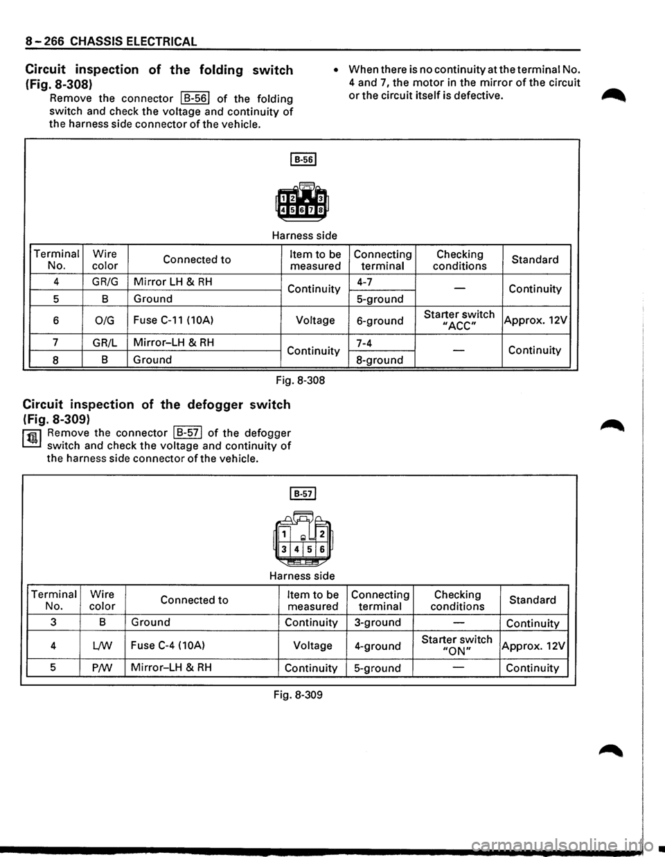
Circuit inspection of the folding switch
(Fig. 8-308)
Remove the connector I 8-561 of the folding
switch and check the voltage and
continuity of
the harness side connector of the vehicle.
• When there is no continuity at the terminal No.
4 and
7, the motor in the mirror of the circuit
or the circuit itself is defective.
I B·56l
f.lh
Harness side
Terminal Wire
Connected
to Item to be Connecting
No. color
measured terminal
4
GR/G Mirror LH & RH Continuity 4-7
5 8 Ground 5-ground
6
0/G Fuse C-11 (10A) Voltage
6-ground
7
GR/L Mirror-LH & RH 7-4
Continuity
8 8
Ground
8-ground
Fig. 8-308
Circuit inspection of the defogger switch
(Fig. 8-309)
rfiil Remove the connector I 8-571 of the defogger
~ switch and check the voltage and continuity of
the harness side connector ofthe vehicle.
Harness side
Terminal Wire
Connected
to No. color
Item to be Connecting
measured terminal
3 8
Ground
Continuity 3-ground
4
L/W Fuse C-4 (10A) Voltage
4-ground
5
P/W Mirror-LH & RH Continuity 5-ground
Fig. 8-309 Checking
conditions
-
Starter switch II ACC"
-
Checking
conditions
Starter switch
"ON"
Standard
Continuity
Approx. 12V
Continuity
Standard
Continuity
Approx. 12V
Continuity
•
Page 1461 of 1928
'"T1 !fl' co I w _. (11
I i i, ~
(
RR
DOOR
LOCK
ACTUATOR
{RHJ
FRT
DOOR
LOCK
SW
(RH
FRT
DOOR
KEY
SW,
(RH),
( ANTI-THEFT
CONTROLLER
RR
DOOR
SW
(RHJ
-------
FRT
DOOR
SW,
(RH)
.~""··
\
/;'~
~
"'··
FRT
DOOR
LOCK
ACTUATOR
(RH)
'-, ..,/j.
',
H-14
'L
y'JIJ.
"·,
H-15"
82
ANTI-THEFT
HORN~-20
"-,
-
RELAY
& FUSE
BOX
~
{FL-1,
FL-2,
F-3)
~
RELAY:
STARTER BATTERY
X::
H-41 B-39 DIODE
B-40 DIODE
B-43 DIODE FUSE
BOX MODESW
TRANSMISSION ,
TAILGATE
LOCK
ACTUATOR
TAILGATE
KEY
SW
TAILGATESW
FRT
DOOR
LOCK
&
/'POWER
WINDOW
SW
H-37 H-38 RRDOOR SW,(LH)
.
RR
DOOR
LOCK
-~ACTUATOR
{LHJ
FRT
DOOR
KEY
SW,
{LH)
-H-28,
H-29
FRT
DOOR
LOCK
ACTUA
TOR
(LH)
(
;g ~ C/) 5 C') ~ 0 z
n :X: ~ (/) 0 m rm ~ n ):a r-0) I N ..... -
Page 1465 of 1928
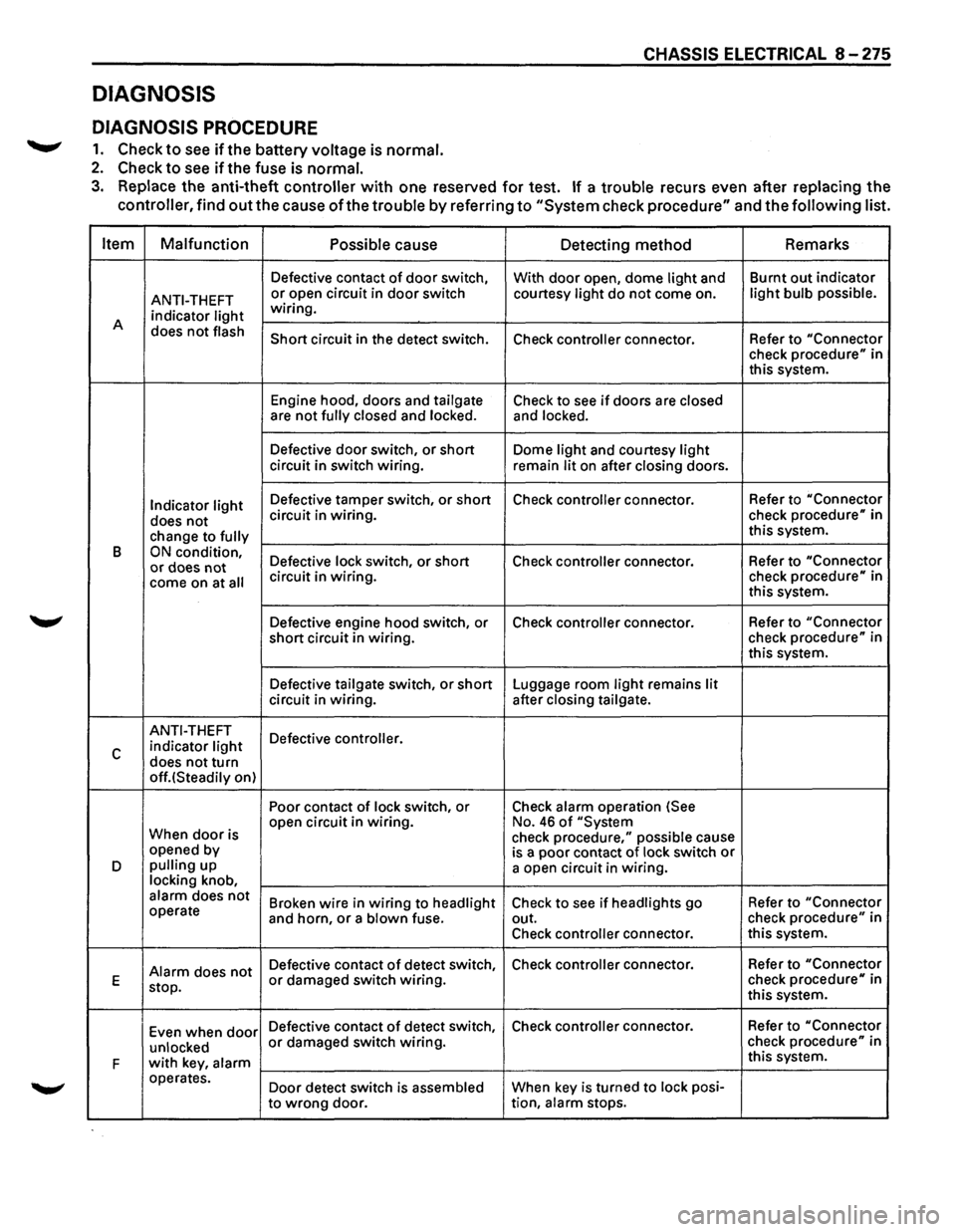
DIAGNOSIS
DIAGNOSIS PROCEDURE
.......,. 1. Check to see ifthe battery voltage is normal.
2. Check to see if the fuse is normal.
CHASSIS ELECTRICAL 8 -275
3. Replace the anti-theft controller with one reserved for test. If a trouble recurs even after replacing the
controller, find
out the cause of the trouble by referring to "System check procedure" and the following list.
Item Malfunction
Possible
cause Detecting method Remarks
Defective
contact of door switch,
With door open, dome light and Burnt
out indicator
ANTI-THEFT or open circuit in door switch courtesy light do not come on. light bulb possible.
indicator light wiring.
A does
not flash Short circuit in the detect switch.
Check controller connector. Refer to "Connector check procedure" in
this system.
Engine hood, doors and
tailgate Check to see if doors are closed are not fully closed and locked. and locked.
Defective door switch, or short Dome light and courtesy light circuit in switch wiring.
remain lit on after closing doors.
Indicator light Defective tamper switch, or short Check controller connector. Refer
to "Connector
does not circuit in wiring. check procedure" in
change to
fully this system.
B
ON condition, Defective lock switch, or short Check controller connector. Refer
to "Connector or does not come on at all circuit in wiring. check procedure" in
this system.
Defective engine hood switch, or Check
controller connector. Refer
to "Connector
short circuit in wiring. check
procedure" in
this system.
Defective
tailgate switch, or short Luggage room light remains lit circuit in wiring. after closing tailgate.
ANTI-THEFT
Defective controller.
c indicator light
does not turn off.(Steadily on) Poor contact
of lock switch, or Check alarm operation (See
When
door is open
circuit in wiring. No. 46 of "System
check procedure," possible cause
opened by
is a poor contact of lock switch or D pulling up
a open circuit in wiring. locking knob, alarm does not Broken wire in wiring to headlight Check to see if headlights go Refer
to "Connector operate
and horn, or a blown fuse. out. check procedure" in
Check
controller connector. this
system.
Alarm does not Defective contact of detect switch, Check controller connector.
Refer to "Connector
E
stop. or damaged switch wiring. check procedure" in
this system.
Even when
door Defective contact of detect switch, Check controller connector. Refer
to "Connector
unlocked
or damaged switch wiring. check procedure" in
F
with key, alarm this system.
operates. Door detect switch is
assembled When key is turned to lock posi-
to
wrong door. tion, alarm stops.
Page 1479 of 1928
::!!
(
(
PARKING
BRAKE
SW
PARKING
BRAKE
LEVER
VEHICLE
SPEED
SENSOR
4WD
INDICATOR
SW,
~
' '
/;~>
TRANSMISSION
3-4SW
IMJT)
"vf;/
RESISTOR;UPSHIFT
."
RELAY;UPSHIFT-1
~":'""
RELAY
& FUSE
BOX-_
(FL-1
,FL-21 BA.
TTERY--.;:;4"~
H-41 H-42
-----;1-"'.,.,-~
THERMO
UNIT
FUEL
TANK
UNIT
(FUEL
TANK)
METERASM
~
16)
1 /
1
(
H-7
/'1'-J
? I n
H-8 H-9 H-25
H-26 C..15 BRAKE
FLUID
SW
(BRAKE
FLUID
TANK}
FUSE
BOX
IC-4,
C-10}
\CLUTCH
SW
(M/T)
CLUTCH
PEDAL
(Mm
(
~ ::xs ~ r-0 0 ~ -0 2
(") :X: ~ en (i) m rm (") ~ g roo I ~
Page 1481 of 1928
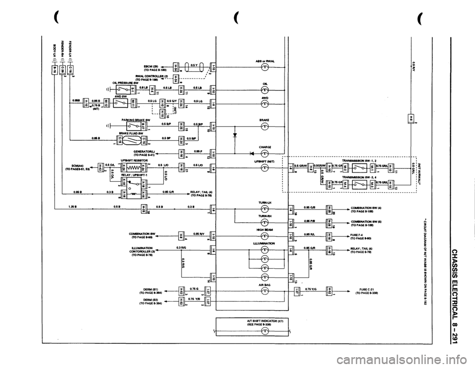
(
I
.. ~ !i:
----
~
........
II
0.858
0.858
0.38
0.85
G/R
1.258
0.58
0.58
0.38
CO-NATIONSW ITOPAGE~
~------_,
cg;c:=~31
0.3 RIG
I
ITO PAGE
8-7S}
:: I~
(
ASS
or RWAL
, • II
OIL ® .awl) ~ -CHARGE
IVT SHIFT
INDICATOR
()(71
{SEE PAGE
11-3351 r:::::-. ~
(
'o .. ~ I J
~~~~
~ ~ ~ '
---------------------------------------------------------
1----
COMBINAliON
8W 1'1
ITO PAGE
11-1011}
1----
CO-NATION
SW(S}
ITO PAGE
11-1011}
~~~~!tEll-SOl ~RELAY;TAILC'I
ITO PAGE
11-78} FUSEC-21 (TO PAGE
8-338}
. n ;;; ~ 0 ~ ;: 3: !il
0
~
::::t
~
)>
)>
(/)
II a;
(/)
..
c;;
~
m
0
r
z
m
... )>
0
~ !
-t ::D
~
c=; )> r co I N CD .....
Page 1486 of 1928
8-296 CHASSIS ELECTRICAL
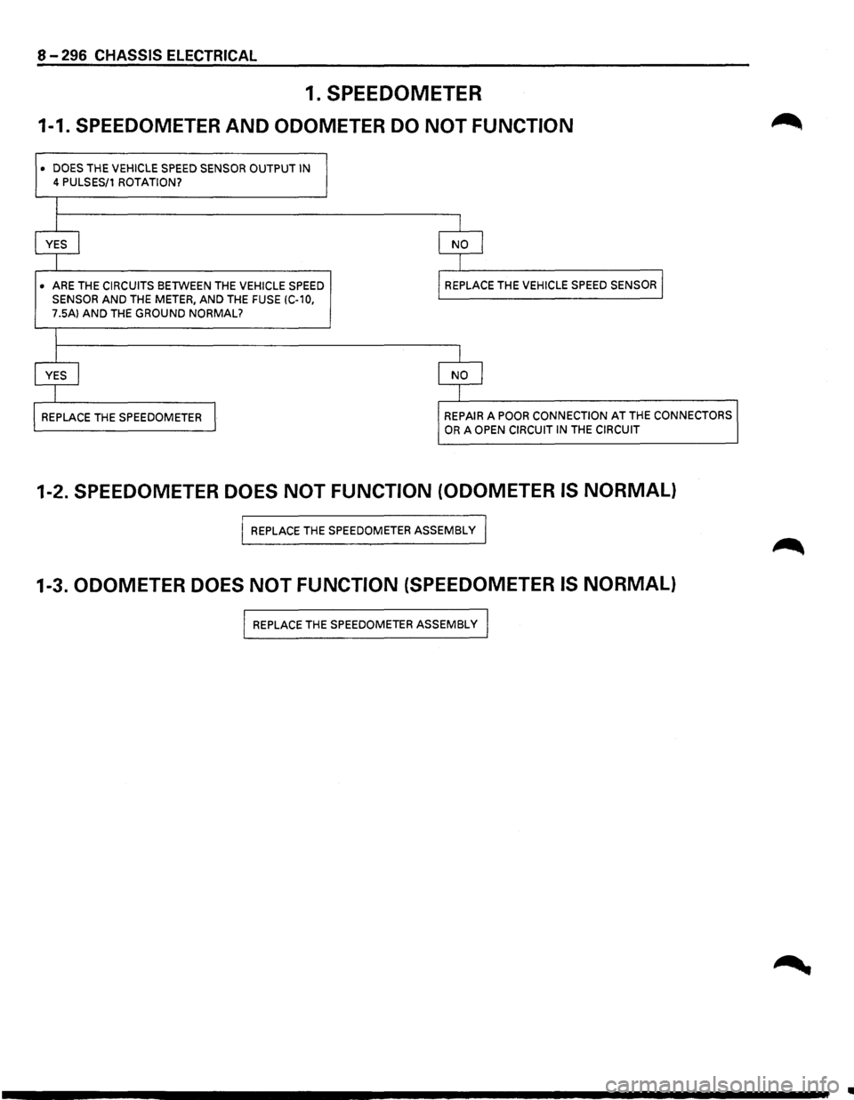
1. SPEEDOMETER
1-1. SPEEDOMETER AND ODOMETER DO NOT FUNCTION
• DOES THE VEHICLE SPEED SENSOR OUTPUT IN
4 PULSES/1 ROTATION?
I
I I
YES I NO I
I
I
• ARE
THE CIRCUITS BETWEEN THE VEHICLE SPEED REPLACE
THE VEHICLE SPEED SENSOR I
SENSOR AND THE METER, AND THE FUSE (C-10,
7.5A) AND THE GROUND NORMAL?
I
j I
YES I NO I
I I
REPLACE
THE SPEEDOMETER I REPAIR A POOR CONNECTION AT THE CONNECTORS
OR A OPEN CIRCUIT IN THE CIRCUIT
1-2. SPEEDOMETER DOES NOT FUNCTION (ODOMETER IS NORMAL)
I REPLACE THE SPEEDOMETER ASSEMBLY I
1-3. ODOMETER DOES NOT FUNCTION (SPEEDOMETER IS NORMAL)
I REPLACE THE SPEEDOMETER ASSEMBLy I
..