lock ISUZU TROOPER 1995 Workshop Manual
[x] Cancel search | Manufacturer: ISUZU, Model Year: 1995, Model line: TROOPER, Model: ISUZU TROOPER 1995Pages: 1928
Page 415 of 1928
4-WHEEL ANTILOCK BRAKE SYSTEM (ABS) 5A4-5
DIAGNOSIS
GENERAL INFORMATION
ABS troubles can be classified to two types, those
which can be detected by the ABS warning light
and those which can be detected as a vehicle
abnormality by the driver.
In either case, locate the fault in accordance with
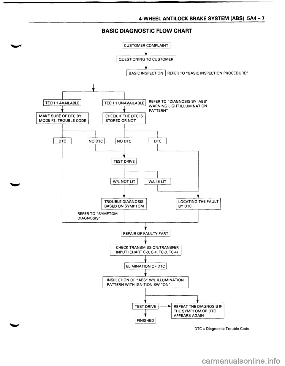
the "BASIC DIAGNOSTIC FLOWCHART" and repair.
Please refer to Section 5A, 5A1, 5A2, 5C for the
diagnosis
of mechanical troubles such as brake
noise, brake
judder (brake pedal or vehicle vibration
felt when braking), uneven braking, and parking
brake
trouble.
ABS SYSTEM SERVICE PRECAUTIONS
Required Tools and Items
Box Wrench
• Brake Fluid
Special Tool
Some diagnosis procedures in this section require
the installation of a special tool.
PINOUT BOX
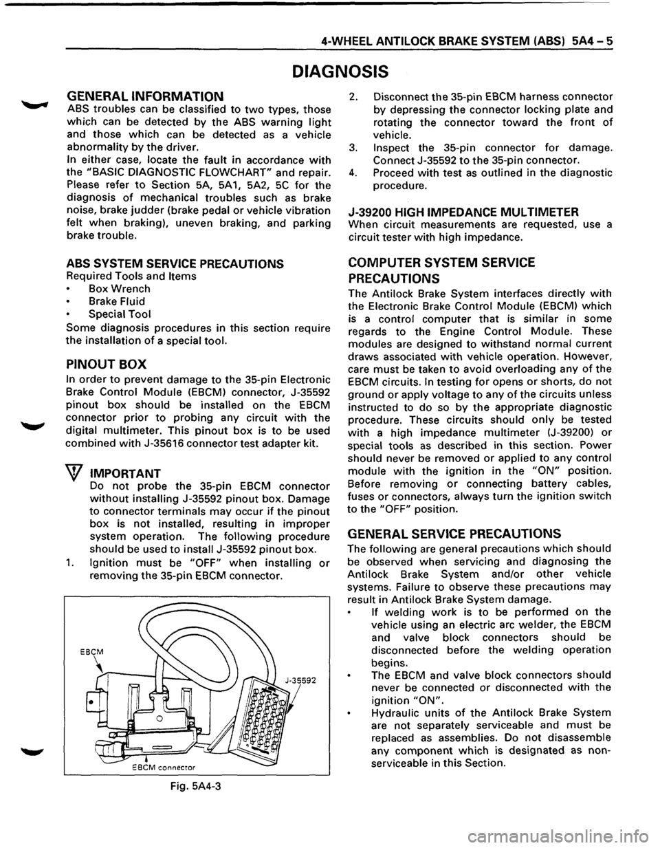
In order to prevent damage to the 35-pin Electronic
Brake
Control Module (EBCM) connector, J-35592
pinout box should be installed on the EBCM
connector prior to probing any circuit with the
digital
multimeter. This pinout box is to be used
combined with J-35616 connector test adapter kit.
W IMPORTANT
Do not probe the 35-pin EBCM connector
without installing J-35592 pinout box. Damage
to connector terminals may occur if the pinout
box is not installed, resulting in improper
system operation. The following procedure
should be used to install J-35592 pinout box.
1. Ignition must be "OFF" when installing or
removing the 35-pin EBCM connector.
Fig. 5A4-3
2. Disconnect the 35-pin EBCM harness connector
by depressing the connector locking plate and
rotating
the connector toward the front of
vehicle.
3. Inspect the 35-pin connector for damage.
Connect J-35592 to the 35-pin connector.
4. Proceed with test as outlined in the diagnostic
procedure.
J-39200 HIGH IMPEDANCE MUL TIMETER
When circuit measurements are requested, use a
circuit tester
with high impedance.
COMPUTER SYSTEM SERVICE
PRECAUTIONS
The Antilock Brake System interfaces directly with
the Electronic Brake Control Module (EBCM) which
is a
control computer that is similar in some
regards
to the Engine Control Module. These
modules are designed to withstand normal current
draws associated with vehicle operation. However,
care
must be taken to avoid overloading any of the
EBCM circuits. In testing for opens or shorts, do not
ground or apply voltage to any of the circuits unless
instructed to
do so by the appropriate diagnostic
procedure. These circuits should only be tested
with a high impedance multimeter (J-39200) or
special tools as described in this section. Power
should never be removed or applied to any control
module with the ignition in the "ON" position.
Before removing
or connecting battery cables,
fuses
or connectors, always turn the ignition switch
to the "OFF" position.
GENERAL SERVICE PRECAUTIONS
The following are general precautions which should
be observed when servicing and diagnosing the
Antilock Brake System and/or
other vehicle
systems. Failure
to observe these precautions may
result in Antilock Brake System damage.
If welding work is to be performed on the
vehicle using an electric arc welder, the EBCM
and valve block connectors should be
disconnected before the
welding operation
begins.
The
EBCM and valve block connectors should
never be connected or disconnected with the
ignition "ON".
Hydraulic units of the Antilock Brake System
are not separately serviceable and must be
replaced
as assemblies. Do not disassemble
any
component which is designated as non
serviceable in
this Section.
Page 416 of 1928
5A4-6 4-WHEEL ANTILOCK BRAKE SYSTEM (ABS)
If only rear wheels are rotated using jacks or
drum tester, the system will diagnose a speed
sensor
malfunction and the "ABS" warning
light will illuminate. But actually no trouble
exists. After inspection stop the engine once
and re-start it,
then make sure that the "ABS"
warning light does not illuminate.
If the battery has been discharged
The engine may stall if the battery has been
completely discharged and the engine is started via
a
jumper cable. This is because the Antilock Brake
System (ABS) requires a
large quantity of
electricity. In this case, wait until the battery is
recharged,
or set the ABS to a non-operative state
by removing the fuse for the ABS (40A). After the
battery has been recharged, stop the engine and
install the ABS fuse. Start the engine again, and
confirm that the ABS warning light does not light.
NOTE ON INTERMITTENTS
As with virtually any electronic system, it is difficult
to identify an intermittent failure. In such a case
duplicating the system malfunction during a test
drive
or a good description of vehicle behavior from
the customer may be helpful in locating a "most
likely" failed component or circuit. The symptom
diagnosis chart may also be useful in isolating the
failure. Most intermittent problems are caused by
faulty electrical connections or wiring. When an
intermittent failure is encountered, check suspect
circuits for:
Suspected harness damage.
• Poor mating of connector halves or terminals
not fully seated in the connector body (backed
out).
Improperly formed or damaged terminals.
TEST DRIVING ABS COMPLAINT
VEHICLES
In case that there has been an abnormality in the
lighting pattern of "ABS" warning light, the fault
can be located in accordance with the "DIAGNOSIS
BY 'ABS' WARNING LIGHT ILLUMINATION
PATTERN". In case of such trouble as can be
detected
by the driver as a vehicle symptom,
however, it is necessary to give a test drive
following the test procedure mentioned below,
thereby reproducing the symptom for trouble
diagnosis on a symptom basis:
1. Start the engine and make sure that the "ABS"
W/L goes OFF. If the W/L remains ON, it
means that the Diagnostic Trouble Code (DTC)
is stored. Therefore, read the code and
locate
the fault.
2. Start the vehicle and accelerate to 30 km/h (19
mph) or more.
3. Slowly brake and stop the vehicle completely.
4. Then restart the vehicle and accelerate to 40
km/h (25 mph) or more.
5. Brake at a time so as to actuate the ABS and ... ~
stop the vehicle.
6. Be cautious of abnormality during the test. If
theW/Lis actuated while driving, read the DTC
and locate the fault.
7. If the abnormality is not reproduced by the
test, make best efforts
to reproduce the
situation reported
by the customer.
8. If the abnormality has been detected, repair in
accordance
with the "SYMPTOM DIAGNOSIS".
NOTE:
Be sure to give a test drive on a wide, even
road
with a small traffic.
If an abnormality is detected, be sure to
suspend the test and start
trouble diagnosis at
once.
II ABS" WARNING LIGHT
When ABS trouble occurs to actuate "ABS"
warning light, the trouble code corresponding to
the trouble is stored in the EBCM. Only ordinary
brake is available with ABS being unactuated. Even
when "ABS" warning light is actuated, if the starter
switch is set
ON after setting it OFF once, the EBCM
checks
up on the entire system and, if there is no
abnormality, judges ABS to work currently and the
warning light is lit normally even though the
trouble code is stored.
NOTE:
Illumination of the "ABS" warning light
indicates that antilock braking is no longer
available. Power assisted braking without
antilock control is still available.
NORMAL OPERATION
II ABS" WARNING LIGHT
When the ignition is first moved from "OFF" to
"RUN", the amber "ABS" warning light will turn
"ON". The "ABS" warning light will turn "ON"
during engine starting and will usually stay "ON"
for approximately three seconds after the ignition
switch is returned to the "ON" position. The
warning light should remain "OFF" at all other
times.
•
Page 417 of 1928
4-WHEEL ANTILOCK BRAKE SYSTEM (ABS) 5A4-7
BASIC DIAGNOSTIC FLOW CHART
I CUSTOMER COMPLAINT I
I
' I QUESTIONING TO CUSTOMER 1
I
BASIC INSPECTION I REFER TO "BASIC INSPECTION PROCEDURE"
+
I
I TECH 1 AVAILABLE I
I TECH 1 UNAVAILABLE REFER TO "DIAGNOSIS BY 'ABS'
t
WARNING LIGHT ILLUMINATION
PATTERN"
I MAKE SURE OF DTC BY I MODE F2: TROUBLE CODE I CHECK IF THE DTC IS STORED OR NOT
I I
I DTC I I NO DTC I I NO
DTC I
I DTC I
I I
I TEST
DRIVEl
I
I W/L NOT LIT I I W/L IS LIT I
I
I TROUBLE DIAGNOSIS I BASED ON SYMPTOM I LOCATING THE FAUL Tj BYDTC
REFER TO "SYMPTOM
DIAGNOSIS"
I REPAIR OF FAUL TV PART I
I
CHECK TRANSMISSION/TRANSFER~ INPUT (CHART C-3, C-4, TC-3, TC-4)
ELIMINATION
OF DTC I
I
INSPECTION OF "ABS" W/L ILLUMINATION
1 PATTERN WITH IGNITION SW "ON"
+ I TEST DRIVE ~ REPEAT THE DIAGNOSIS IF
THE SYMPTOM OR DTC
APPEARS AGAIN
I FINISHED I
DTC = Diagnostic Trouble Code
Page 418 of 1928
5A4-8 4-WHEEL ANTILOCK BRAKE SYSTEM (ABS)
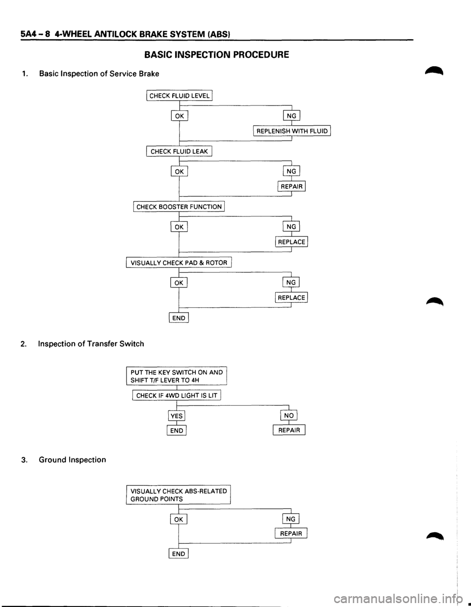
BASIC INSPECTION PROCEDURE
1. Basic Inspection of Service Brake
VISUALL V CHECK PAD & ROTOR
2. Inspection of Transfer Switch
3. Ground Inspection
PUT THE KEY SWITCH ON AND
SHIFT T/F LEVER TO 4H
CHECK IF 4WD LIGHT IS LIT
VISUALL
V CHECK ASS-RELATED
GROUND POINTS
•
Page 419 of 1928
4-WHEEL ANTILOCK BRAKE SYSTEM (ABS) 5A4-9
MEMO
Page 420 of 1928
5A4-10 4-WHEEL ANTILOCK BRAKE SYSTEM (ABS)
TECH 1 TOOL
TECH 1 is an effective tool for the diagnosis of
electrical fault of Antilock Brake System (ASS) and
system check.
Although you can completely
diagnose the system without a TECH 1, using the
tool is quicker. In the following procedures, the
!TECH 11 symbol shows where the TECH 1 is used.
The
t::nettll symbol means the tool is not used.
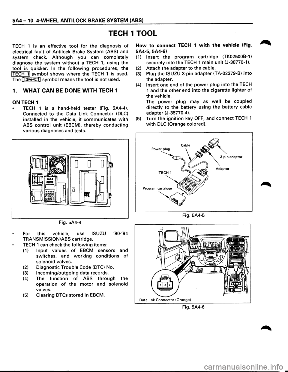
1. WHAT CAN BE DONE WITH TECH 1
ON TECH 1
TECH 1 is a hand-held tester (Fig. 5A4-4).
Connected
to the Data Link Connector (DLC)
installed in the vehicle, it communicates with
ABS control unit (EBCM), thereby conducting
various diagnoses and tests.
Fig. 5A4-4
For this
vehicle, use ISUZU '90-'94
TRANSMISSION/ASS cartridge.
TECH 1 can check the following items:
(1) Input values of EBCM sensors and
switches, and
working conditions of
solenoid valves.
(2) Diagnostic Trouble Code (DTC) No.
(3) Incoming/outgoing data records.
(4) The function of ABS through the
operation
of the motor and solenoid
valves.
(5) Clearing DTCs stored in EBCM.
How to connect TECH 1 with the vehicle (Fig.
5A4·5, 5A4-6)
(1) Insert the program cartridge (TK02500B-1)
securely
into the TECH 1 main unit (J-38770-1).
(2) Attach the adapter to the cable.
(3) Plug the ISUZU 3-pin adapter (T A-02279-8) into
the adapter.
(4) Insert one end of the power plug into the TECH
1 and the other end into the cigarette lighter of
the vehicle.
The power plug may as well be coupled
directly
to the battery using the battery cable
adapter (J-38770-4).
(5) Turn the ignition key OFF, and connect TECH 1
with DLC (Orange colored).
Fig. 5A4-5
Data link Connector (Orange)
Fig. 5A4-6
Page 421 of 1928
4-WHEEL ANTILOCK BRAKE SYSTEM (ABS) 5A4-11
2. HOW TO USE TECH 1
Operating procedure for TECH 1
After connecting with the vehicle, turn the ignition
key
ON and follow the flow chart.
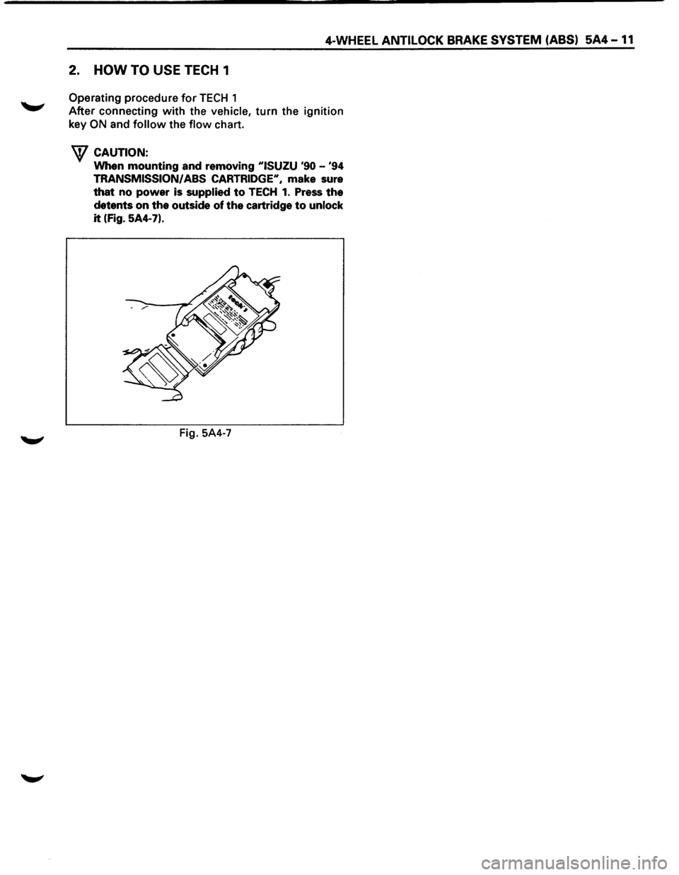
W CAUTION:
When mounting and removing "ISUZU '90 -'94
TRANSMISSION/ ABS CARTRIDGE", make sure
that no power is supplied to TECH 1. Press the
detents on the outside of the cartridge to unlock
it (Fig. 5A4-7).
Fig. 5A4-7
Page 422 of 1928
5A4-12 4-WHEEL ANTILOCK BRAKE SYSTEM (ABS)
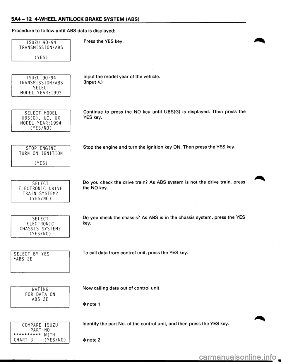
Procedure to follow until ABS data is displayed:
ISUZU 90-94
TRANSMISSION/ASS
C YES)
ISUZU 90-94
TRANSMISSION/ASS
SELECT
MODEL YEAR:l99?
SELECT MODEL
UBSCG), UC, UX
MODEL YEAR:l994
CYES/NO)
STOP ENGINE
TURN ON IGNITION
C YES)
SELECT
ELECTRONIC DRIVE
TRAIN SYSTEM?
CYES/NO)
SELECT
ELECTRONIC
CHASSIS SYSTEM?
CYES/NO)
SELECT BY YES
*ABS-2E
WATING
FOR DATA ON
ABS-2E
COMPARE ISUZU
PART-NO
********** WITH
CHART 3 CYES/NO)
Press the YES key.
Input the model year of the vehicle.
(Input
4.)
Continue to press the NO key until UBS(G) is displayed. Then press the
YES key.
Stop the engine and turn the ignition key
ON. Then press the YES key.
Do you check the drive train? As ABS system is
not the drive train, press
the
NO key.
Do you check the chassis? As ABS
is in the chassis system, press the YES
key.
To
call data from control unit, press the YES key.
Now calling data out of control unit.
Identify the part No. of the control unit, and then press the YES key.
Page 423 of 1928
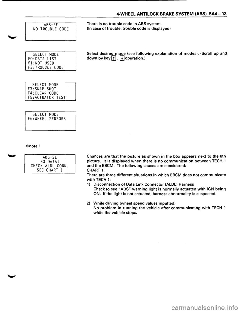
ABS-2E
NO TROUBLE CODE
SELECT MODE
FO:DATA LIST
F1: NOT USED
F2:TROUBLE CODE
SELECT MODE
F3:SNAP SHOT
F4:CLEAR CODE
F5:ACTUATOR TEST
SELECT MODE
F6:WHEEL SENSORS
*note 1
ABS-2E
NO DATA!
CHECK ALDL CONN.
SEE CHART 1
4-WHEEL ANTILOCK BRAKE SYSTEM (ABS) 5A4-13
There is no trouble code in ABS system.
(In case of trouble, trouble code is displayed)
Select
desired mode (see following explanation of modes). (Scroll up and
down by key III. m operation.)
Chances are
that the picture as shown in the box appears next to the 8th
picture.
It is displayed when there is no communication between TECH 1
and the EBCM. The
following causes are considered:
CHART
1:
There are three different situations in which EBCM does not communicate
with TECH 1:
1) Disconnection of Data Link Connector (ALDL) Harness
Check
to see "ABS" warning light is normally actuated with IGN being
ON. lfthe light is not actuated, harness abnormality is suspected.
2) While driving (wheel speed values inputted)
No problem in running the vehicle after communicating with TECH 1
while the vehicle stops.
Page 424 of 1928
5A4 -14 4-WHEEL ANTILOCK BRAKE SYSTEM (ABS)
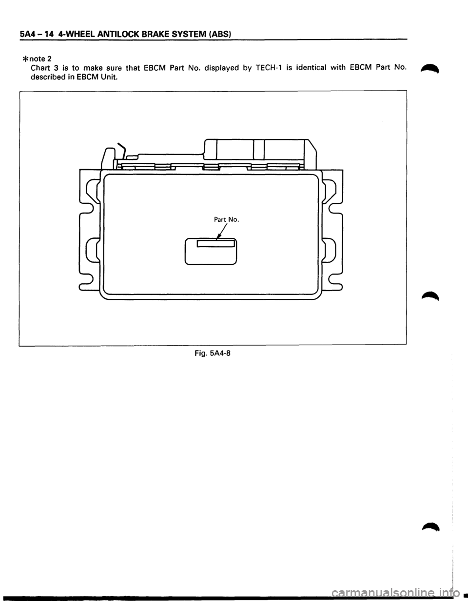
*note 2
Chart 3 is to make sure that EBCM Part No. displayed by TECH-1 is identical with EBCM Part No. ~
described in EBCM Unit.
Part No.
I
Fig. 5A4-8
•