lock ISUZU TROOPER 1995 Workshop Manual
[x] Cancel search | Manufacturer: ISUZU, Model Year: 1995, Model line: TROOPER, Model: ISUZU TROOPER 1995Pages: 1928
Page 1857 of 1928
,__,.
3
1
Linkage bush
7d
--L·W·B I
Linkage bush
7c
BODY 1D-99
S·W·B
==c=
6g
L ___ _
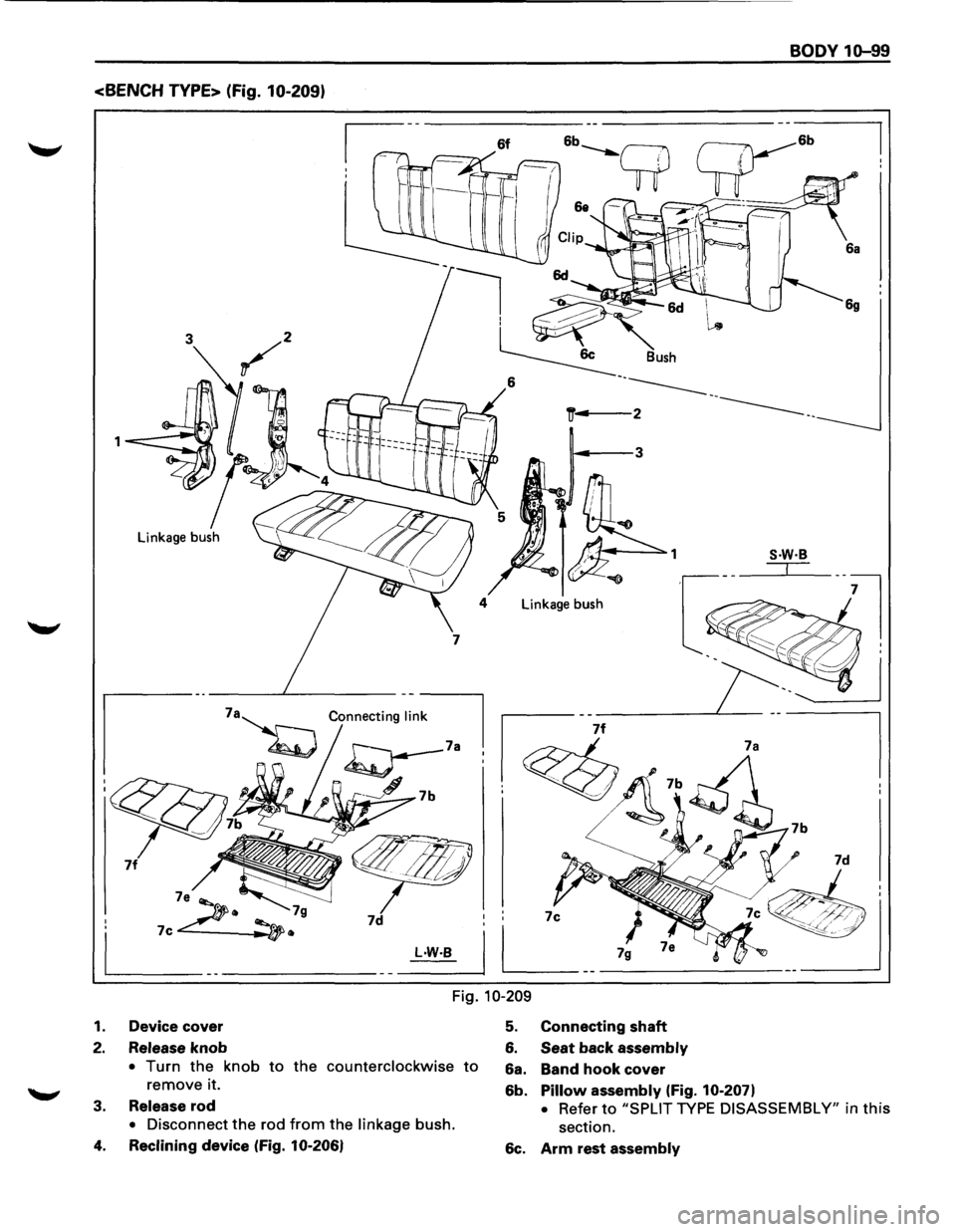
Fig. 10-209
1. Device cover 5. Connecting shaft
2. Release knob 6. Seat back assembly
• Turn the knob to the counterclockwise to 6a. Band hook cover remove it.
6b. Pillow assembly (Fig. 10-207)
3. Release rod • Refer to "SPLIT TYPE DISASSEMBLY" in this
• Disconnect the rod from the linkage bush. section .
4. Reclining device (Fig. 10-2061 6c. Arm rest assembly
Page 1858 of 1928
1Q-100 BODY
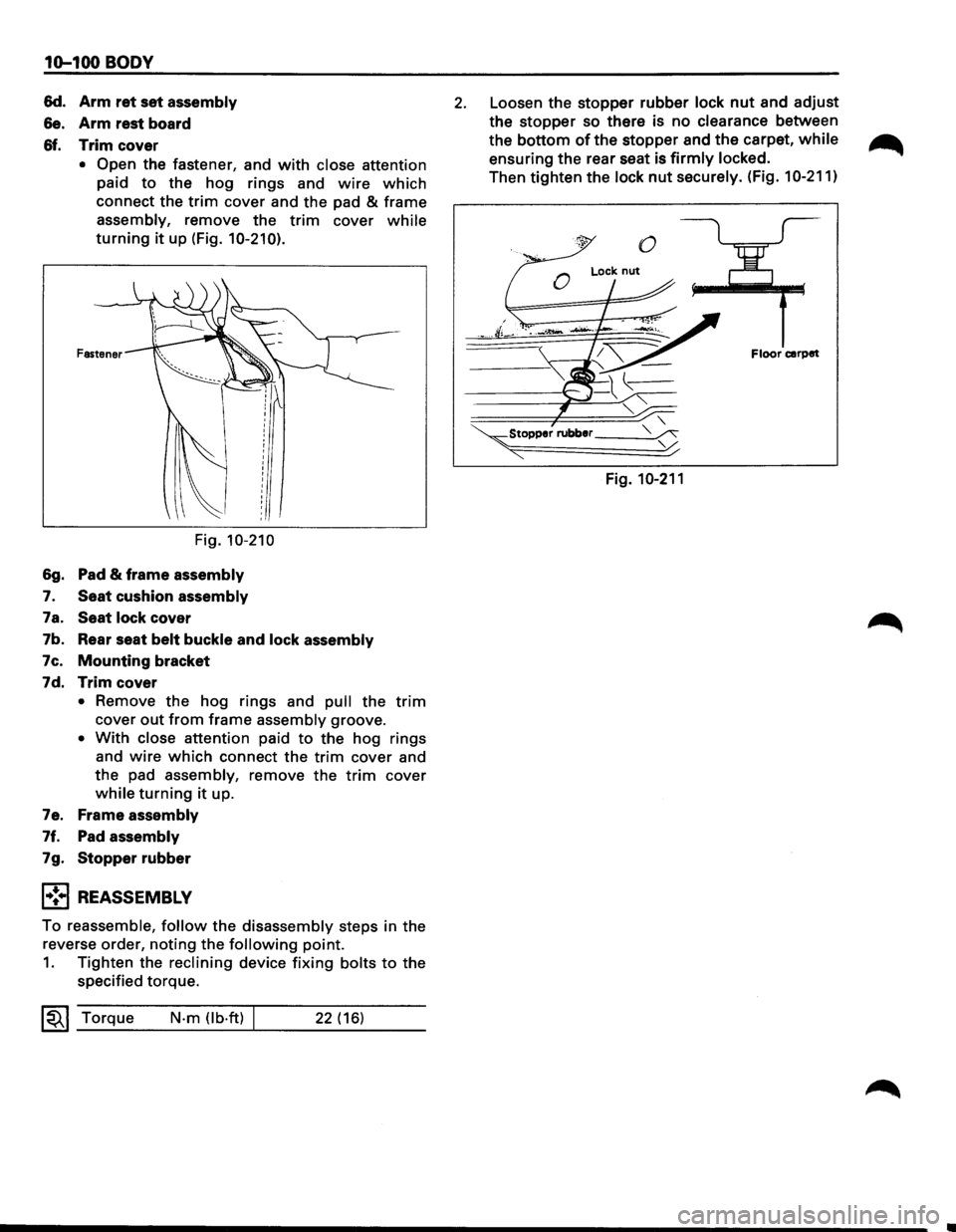
&d. Arm ret set assembly
&e. Arm rest board
&f. Trim cover
• Open the fastener, and with close attention
paid
to the hog rings and wire which
connect the trim cover and the pad & frame
assembly, remove the trim cover while
turning it up (Fig. 10-210).
Fastener
Fig. 10-210
&g. Pad & frame assembly
7. Seat cushion assembly
7a. Seat lock cover
7b. Rear seat
belt buckle and lock assembly
7c.
Mounting bracket
7d.
Trim cover
• Remove the hog rings and pull the trim
cover out from frame assembly groove.
• With close attention paid to the hog rings
and
wire which connect the trim cover and
the pad
assembly, remove the trim cover
while turning it up.
7e. Frame
assembly
7f. Pad assembly
7g. Stopperrubber
l•!•l REASSEMBLY
To reassemble, follow the disassembly steps in the
reverse order,
noting the following point.
1. Tighten the reclining device fixing bolts to the
specified torque.
~~~ Torque N-m (lb-ft) 22 (16)
2. Loosen the stopper rubber lock nut and adjust
the
stopper so there is no clearance between
the
bottom of the stopper and the carpet, while
ensuring the rear seat is firmly locked.
Then tighten the lock nut securely. (Fig. 10-211)
Floor carpet
~Stopper rubber __ _
"""' Fig. 10-211
Page 1866 of 1928
10-108 BODY
!••I INSTALLATION
To install, follow the removal steps in the reverse
order,
noting the following points.
1. Be sure to install the lower side anchor plate
straight horizontally, with mounting hole of the
plate at the center. (Fig. 10-222)
2. Tighten the seat belt anchor bolts to the
specified torque.
~~~ Torque N·m (lb.ft) / 39 (29)
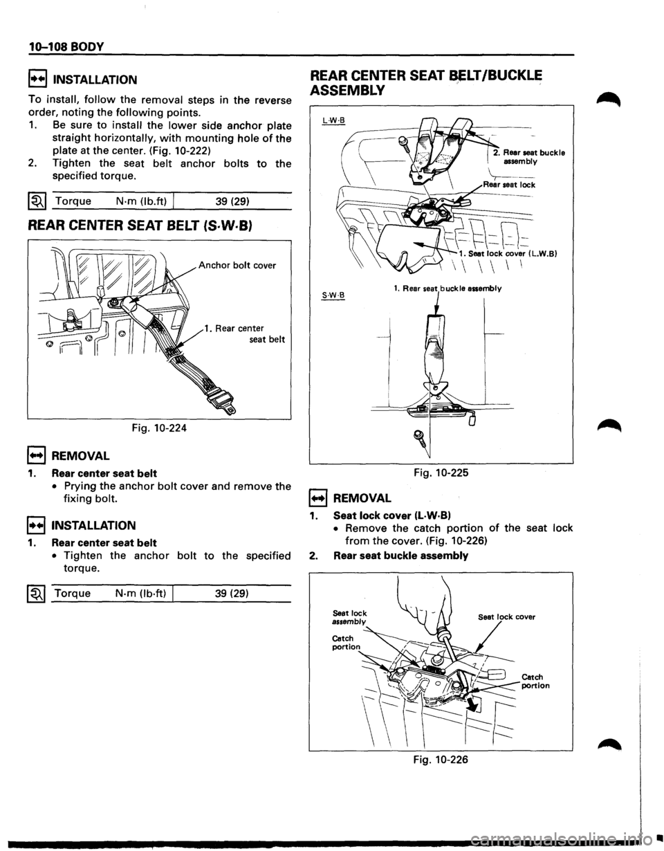
REAR CENTER SEAT BELT (S·W·B)
Anchor bolt cover
1. Rear center
seat
belt
Fig. 10-224
1••1 REMOVAL
1. Rear center seat belt
• Prying the anchor bolt cover and remove the
fixing bolt.
I••IINSTALLATION
1. Rear center seat belt
• Tighten the anchor bolt to the specified
torque.
~~~ Torque N-m (lb·ft) 39 (29)
REAR CENTER SEAT ~LT/BUCKLE
ASSEMBLY
1••1 REMOVAL
2. Rear seat buckle
assembly
\----Rear seat lock
--t\8~ 1. Seat lock cover (L.W.B)
1. Rear seat buckle assembly
Fig. 10-225
1. Seat lock cover (L·W·B)
• Remove the catch portion of the seat lock
from the cover. (Fig. 10-226)
2. Rear seat buckle assembly
Catch
portion
Fig. 10-226
Catch
portion
•
Page 1867 of 1928
BODY 1G-109
E) INSTALLATION REAR SEAT LOCK ASSEMBLY
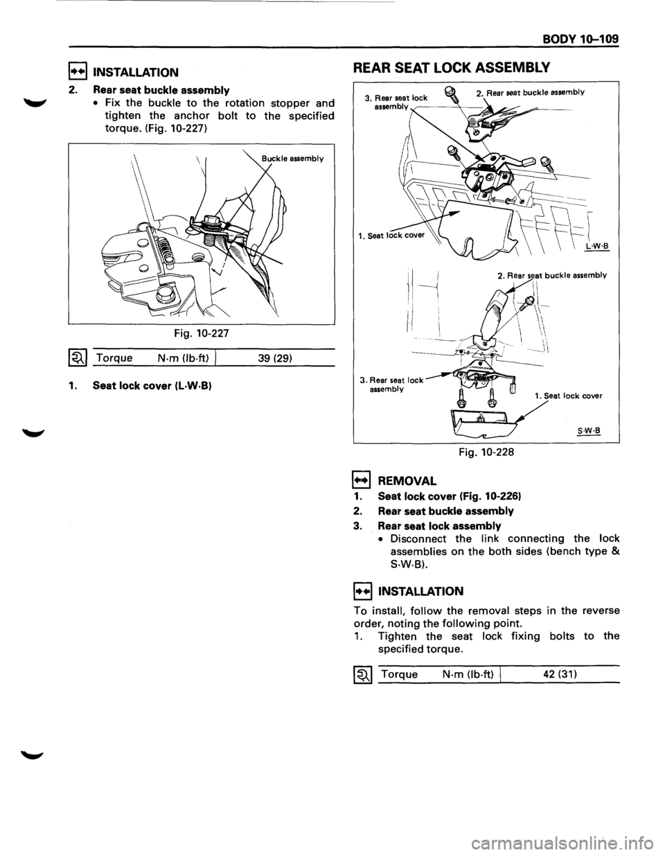
2. Rear seat buckle assembly
"-"' • Fix the buckle to the rotation stopper and
tighten the anchor bolt to the specified
torque. (Fig. 10-227)
Fig. 10-227
1~1 Torque N-m (lb-ft) I 39 (29)
1. Seat lock cover (l·W·B)
I --j I
3. Rear seat lock ---~~ai~~'"ll assembly
' 1. Seat lock cover
~
Fig. 10-228
1••1 REMOVAL
1. Seat lock cover (Fig. 10-226)
2. Rear seat
buckle assembly
3. Rear seat lock assembly
• Disconnect the link connecting the lock
assemblies
on the both sides (bench type &
S-W·B).
I••! INSTALLATION
To install, follow the removal steps in the reverse
order,
noting the following point.
1. Tighten the seat lock fixing bolts to the
specified
torque.
~~~ Torque N·m (lb·ft) 42 (31)
Page 1869 of 1928
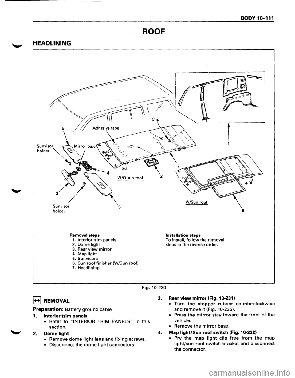
BODY 10-111
ROOF
HEADLINING
~---~~I
~r CUp ''-. _ __j
5 1 Adh.,;,;, tap• . T
1
W /0 sun roof 2
Sunvisor
holder 5
Removal steps 1. Interior trim panels 2. Dome light 3. Rear view mirror 4. Map light 5. Sunvisors 6. Sun roof finisher (W/Sun roof) 7. Headlining W/Sun
roof
Installation steps To install, follow the removal steps
in the reverse order. 6
Fig. 10-230
1••1 REMOVAL
Preparation: Battery ground cable
1. Interior trim panels
•
Refer to "INTERIOR TRIM PANELS" in this
section.
2. Dome light
• Remove dome light lens and fixing screws.
• Disconnect the dome light connectors.
3. Rear view mirror (Fig. 10-231)
• Turn the stopper rubber counterclockwise
and remove
it (Fig. 10-235).
• Press the mirror stay toward the front of the
vehicle.
•
Remove the mirror base.
4. Map light/Sun roof switch (Fig. 10-232)
• Pry the map light clip free from the map
light/sun roof switch bracket and disconnect
the connector.
Page 1892 of 1928
10-134 BODY
CHILD RESTRAINT
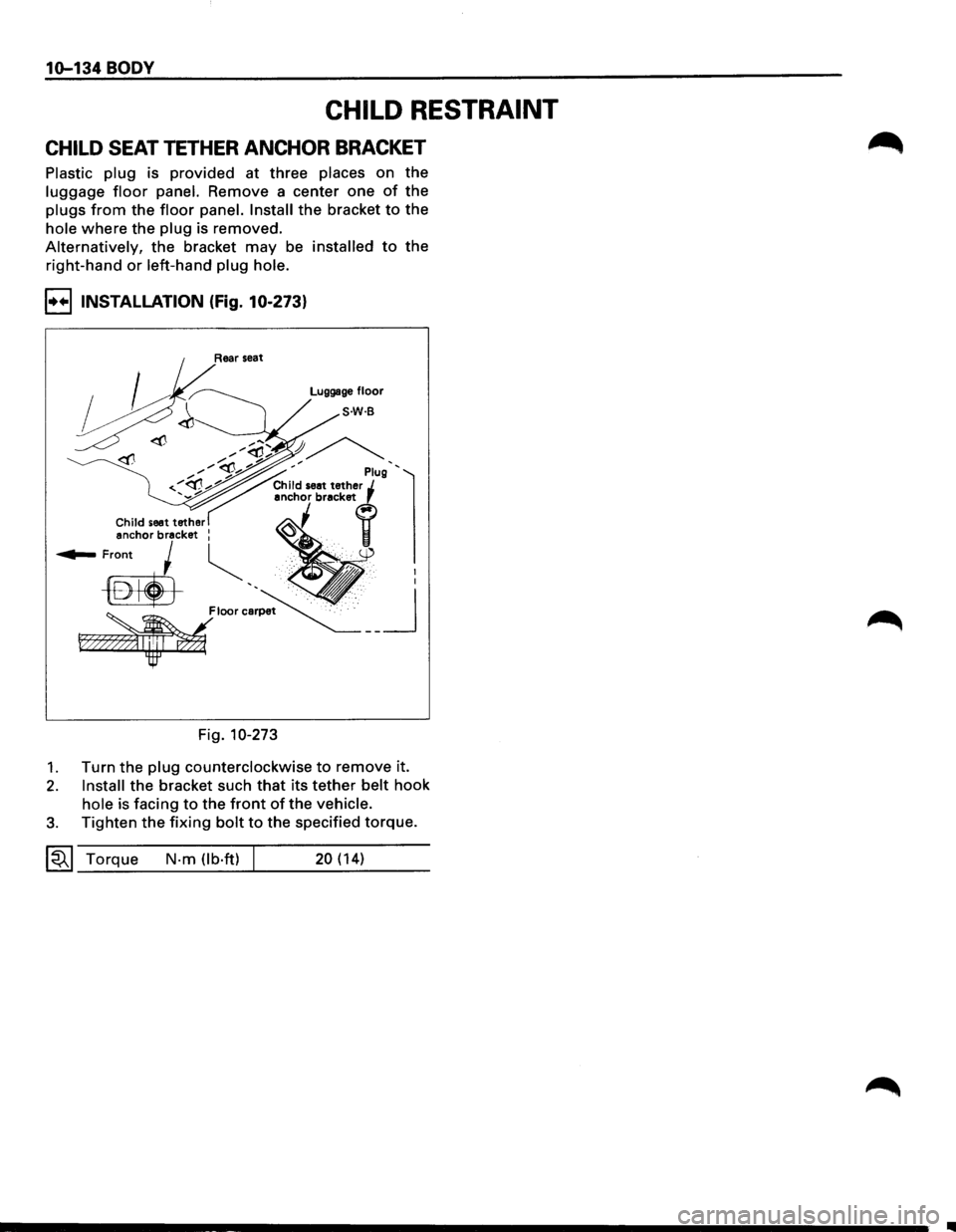
CHILD SEAT TETHER ANCHOR BRACKET
Plastic plug is provided at three places on the
luggage floor panel. Remove a center one of the
plugs from the floor panel. Install the bracket to the
hole where the plug is removed.
Alternatively, the bracket may be installed to the
right-hand
or left-hand plug hole.
I••IINSTALLATION (Fig. 10-273)
,/<(!.., )~ ~ .., "' ' "'"' '''-'"-"' ' Plug '
'-."" anchor bracket r ... --
~Front ~ ~ ,.
-®liJ ', • :
~loom~ __ j
F?»
Fig. 10-273
1. Turn the plug counterclockwise to remove it.
2. Install the bracket such that its tether belt hook
hole is facing to the front of the vehicle.
3. Tighten the fixing bolt to the specified torque.
~~~ Torque N-m (lb·ft) 20 (14)
Page 1893 of 1928
BODY 1Q-135
KEY
KEY CODING
KEY USAGE AND IDENTIFICATION
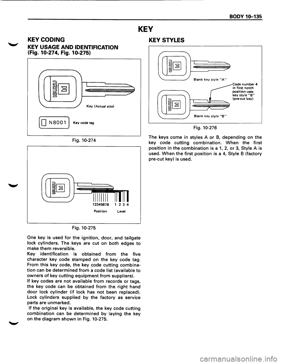
(Fig. 10-274, Fig. 10-275)
I
Key (Actual size)
( 0 N8001) Keycodetag
Fig. 10-274
12345678 1 2 3 4
Position Level
Fig. 10-275
One
key is used for the ignition, door, and tailgate
lock cylinders.
The keys are cut on both edges to
make them reversible.
Key identification is obtained from the five
character key code stamped on
the key code tag.
From
this key code, the key code cutting combina
tion can be determined from a code list (available to
owners of key cutting equipment from suppliers).
If key codes are not available from records or tags,
the key code can be obtained
from the right hand
door lock cylinder (if lock has not been replaced).
Lock cylinders supplied by the factory as service
parts are unmarked.
If the original key is available, the key code cutting
combination can be determined by laying the key
on the diagram
shown in Fig. 10-275.
KEY STYLES
Blank key style "A"
Blank key style "B"
Fig. 10-276
Code number 4
in first notch position uses key style "B" (pre-cut key)
The keys come in styles A or 8, depending on the
key code cutting combination. When the
first
position in the combination is a 1, 2, or 3, Style A is
used. When the
first position is a 4, Style 8 (factory
pre-cut key) is used.