4WD ISUZU TROOPER 1995 User Guide
[x] Cancel search | Manufacturer: ISUZU, Model Year: 1995, Model line: TROOPER, Model: ISUZU TROOPER 1995Pages: 1928
Page 426 of 1928
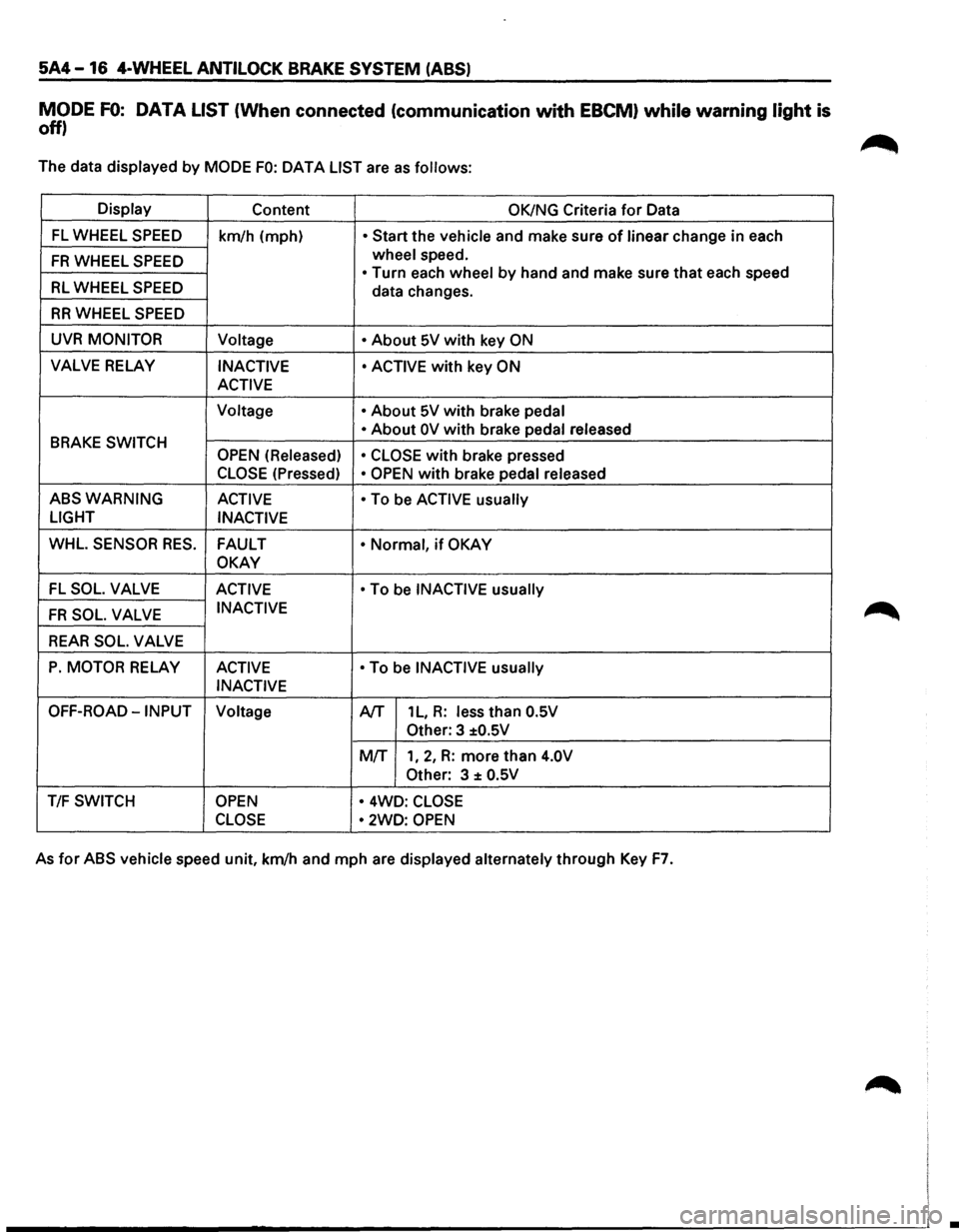
5A4-16 4-WHEEL ANTILOCK BRAKE SYSTEM (ABS)
MODE FO: DATA LIST (When connected (communication with EBCM) while warning light is
off)
The data displayed by MODE FO: OAT A LIST are as follows:
Display Content OK/NG Criteria for Data
FL WHEEL SPEED km/h (mph) • Start the vehicle and make sure of linear change in each
FR WHEEL SPEED wheel speed.
• Turn each wheel by hand and make sure that each speed RL WHEEL SPEED data changes.
RR WHEEL SPEED
UVR MONITOR
Voltage • About 5V with key ON
VALVE RELAY INACTIVE • ACTIVE with key ON
ACTIVE
Voltage •
About 5V with brake pedal
BRAKE SWITCH • About OV with brake pedal
released
OPEN (Released)
• CLOSE
with brake pressed
CLOSE (Pressed) • OPEN with brake pedal released
ABSWARNING ACTIVE
• To be ACTIVE usually
LIGHT
INACTIVE
WHL. SENSOR RES. FAULT • Normal, if OKAY
OKAY
-FL SOL. VALVE ACTIVE • To be INACTIVE usually
FR SOL. VALVE INACTIVE
REAR SOL. VALVE
P. MOTOR RELAY ACTIVE • To be INACTIVE usually
INACTIVE
OFF-ROAD-INPUT Voltage A/T 1 L, R: less than O.SV
Other: 3 ±O.SV
MIT 1, 2, R: more than 4.0V
Other:
3 ± O.SV
T/F SWITCH OPEN • 4WD: CLOSE
CLOSE •
2WD: OPEN
As for ABS vehicle speed unit, km/h and mph are displayed alternately through Key F7.
•
Page 427 of 1928
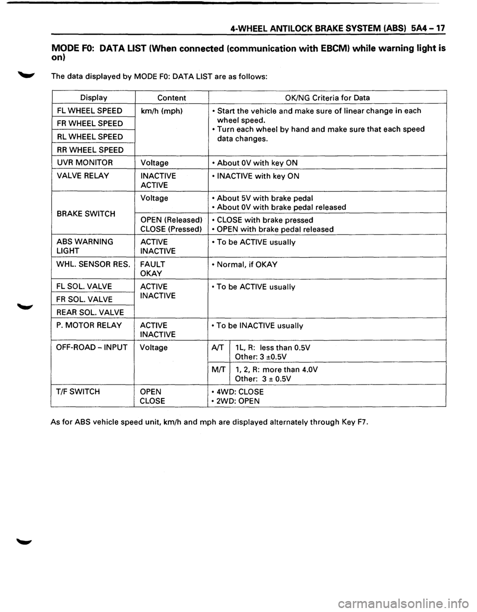
4-WHEEL ANTILOCK BRAKE SYSTEM (ABS) 5A4-17
MODE FO: DATA LIST (When connected (communication with EBCM) while warning light is
on)
._,. The data displayed by MODE FO: DATA LIST are as follows:
Display
Content OK/NG Criteria for Data
FL WHEEL SPEED
km/h (mph) • Start the vehicle and make sure of linear change in each
FR WHEEL SPEED wheel speed.
• Turn each wheel by hand and make sure that each speed RL WHEEL SPEED data changes.
RR WHEEL SPEED
UVR MONITOR Voltage • About OV with key ON
VALVE RELAY INACTIVE • INACTIVE with key ON
ACTIVE
Voltage • About 5V with brake pedal
BRAKE
SWITCH • About OV with brake
pedal released
OPEN (Released) • CLOSE with brake pressed
CLOSE (Pressed) • OPEN with brake pedal released
ABSWARNING ACTIVE • To be ACTIVE usually
LIGHT
INACTIVE
WHL.
SENSOR RES. FAULT • Normal, if OKAY
OKAY
FL SOL. VALVE ACTIVE • To be ACTIVE usually
FR SOL. VALVE INACTIVE
REAR SOL. VALVE
P. MOTOR RELAY
ACTIVE • To be INACTIVE usually
INACTIVE
OFF-ROAD-INPUT Voltage A/T 1 L, R: less than 0.5V
Other:
3 ±0.5V
MIT
1, 2, R: more than 4.0V
Other:
3 ± 0.5V
T/F SWITCH OPEN • 4WD: CLOSE
CLOSE •
2WD: OPEN
As for ABS vehicle speed unit, km/h and mph are displayed alternately through Key F7.
Page 444 of 1928
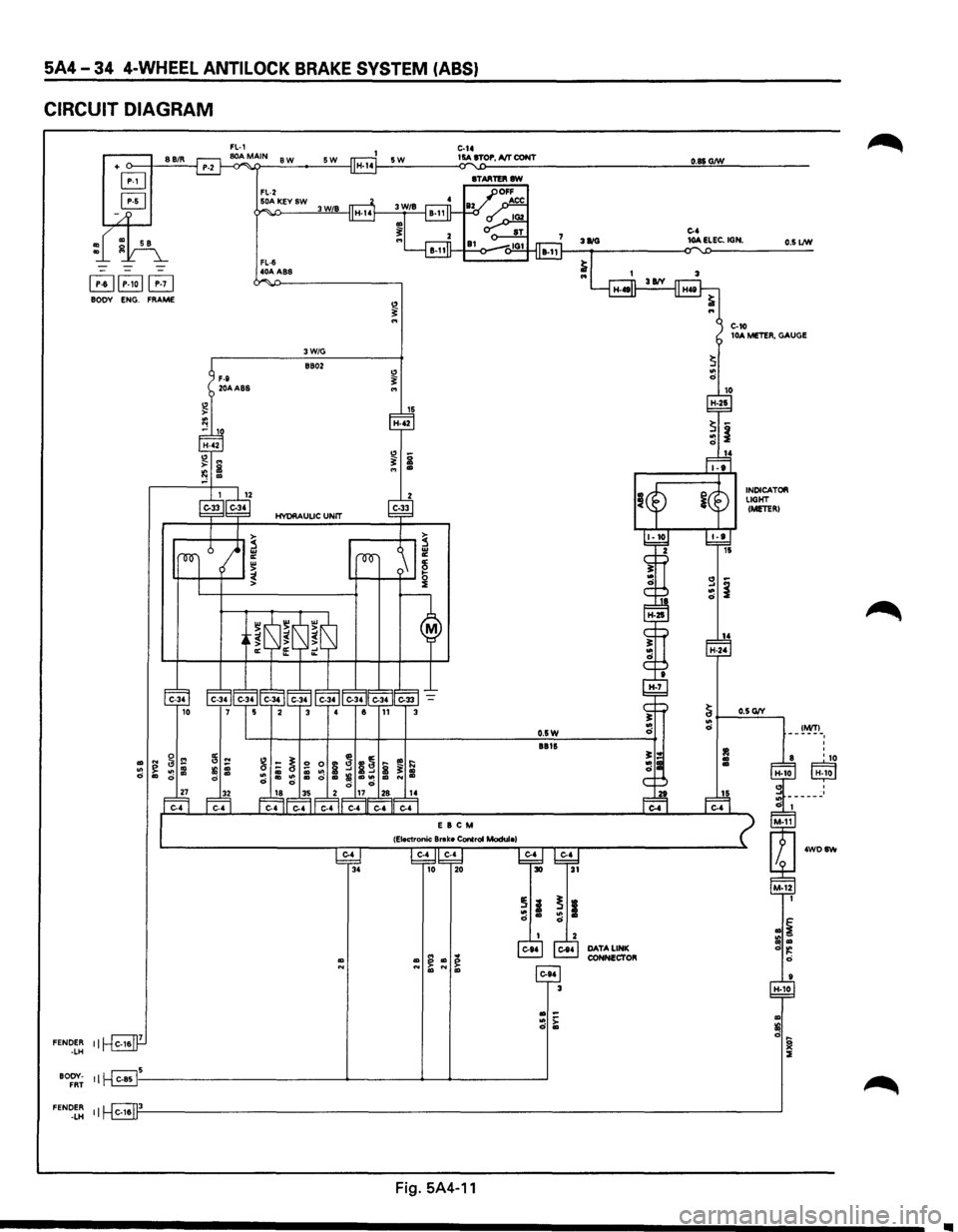
5A4-34 4-WHEEL ANTILOCK BRAKE SYSTEM (ABS)
CIRCUIT DIAGRAM
FENDER -LH
BODY· FRT
FENDER -LH
+ o-----J----'8:..:8:..:/R~
B
EJ
~~B BODY ENG. FRAME
II
11~5
II C-16
E 8 C M
Fig. 5A4-11
o.sw 8BI6
.. -d ~
DATA LINK CONNECTOR
C-4 lOA ELEC. IGN. O.Sl/W
C-10 lOA METER, GAUGE
H-24
IM/TI ------~
H-10
I I I 10
I H;lo I
4WDS1111
•
Page 478 of 1928
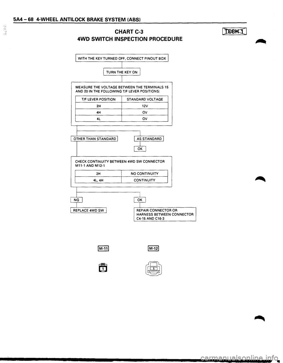
5A4-68 4-WHEEL ANTILOCK BRAKE SYSTEM (ABS)
CHART C-3 [@f((l
4WD SWITCH INSPECTION PROCEDURE
WITH THE KEY TURNED OFF, CONNECT PINOUT BOX
I TURN THE KEY ON I
MEASURE THE VOLTAGE BETWEEN THE TERMINALS 15 AND 20 IN THE FOLLOWING T/F LEVER POSITIONS:
T!F LEVER POSITION STANDARD VOLTAGE
2H 12V
4H ov
4L ov
l OTHER THAN STANDARD j AS STANDARD I
clJ
CHECK CONTINUITY BETWEEN 4WD SW CONNECTOR M11-1 AND M12-1
I
2H
I
NO CONTINUITY
I 4L, 4H CONTINUITY
$ $
REPLACE 4WD sw I REPAIR CONNECTOR OR HARNESS BETWEEN CONNECTOR C4-15 AND C16-3
Ill
Page 479 of 1928
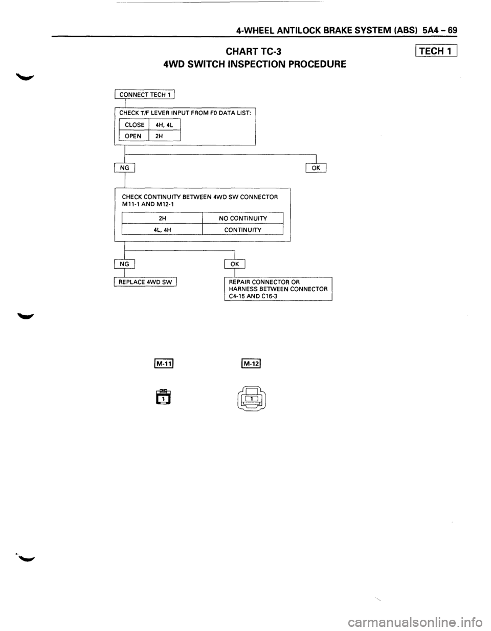
4-WHEEL ANTILOCK BRAKE SYSTEM (ABS) 5A4-69
CHARTTC-3
4WD
SWITCH INSPECTION PROCEDURE
CHECK CONTINUITY BElWEEN 4WD SW CONNECTOR M11-1 AND M12-1
2H
4L,4H
NO CONTINUITY
CONTINUITY
REPAIR CONNECTOR
OR HARNESS BElWEEN CONNECTOR C4-15 AND C16-3
I TECH 1 I
Page 907 of 1928
AUTOMATIC TRANSMISSION (4L30-E) 7 A-35
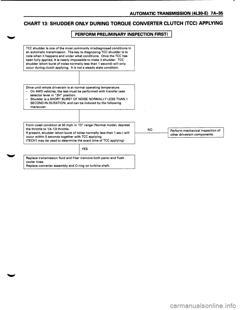
CHART 13: SHUDDER ONLY DURING TORQUE CONVERTER CLUTCH (TCC) APPLYING
PERFORM PRELIMINARY INSPECTION FIRST!
TCC shudder is one of the most commonly misdiagnosed conditions in
an automatic transmission. The key to diagnosing TCC shudder is to note when it happens and under what conditions. Once the TCC has
been fully applied, it is nearly impossible to make it shudder. TCC shudder {short burst of noise normally less than 1 second) will only
occur during clutch applying. It is not a steady state condition.
Drive
until whole drivetrain is at normal operating temperature.
-On 4WD vehicles, the test must be performed with transfer case selector lever in "2H" position.
- Shudder is a SHORT BURST OF NOISE NORMALLY LESS THAN 1
SECOND IN DURATION, and can be induced by the following maneuver:
From coast condition at
50 mph in "D" range {Normal mode), depress
the throttle to 1/4-1/3 throttle. If present, shudder {short burst of noise normally less than 1 sec.) will occur within 5 seconds together with TCC applying. {TECH1 may be used to determine the exact time of TCC applying)
YES
Replace transmission fluid and filter {remove both pans) and flush
cooler lines.
Replace
converter assembly and 0-ring on turbine shaft.
,__ __ N_o ___ ---<1 Perform mechanical inspection of I j other drivetrain components.
Page 1095 of 1928
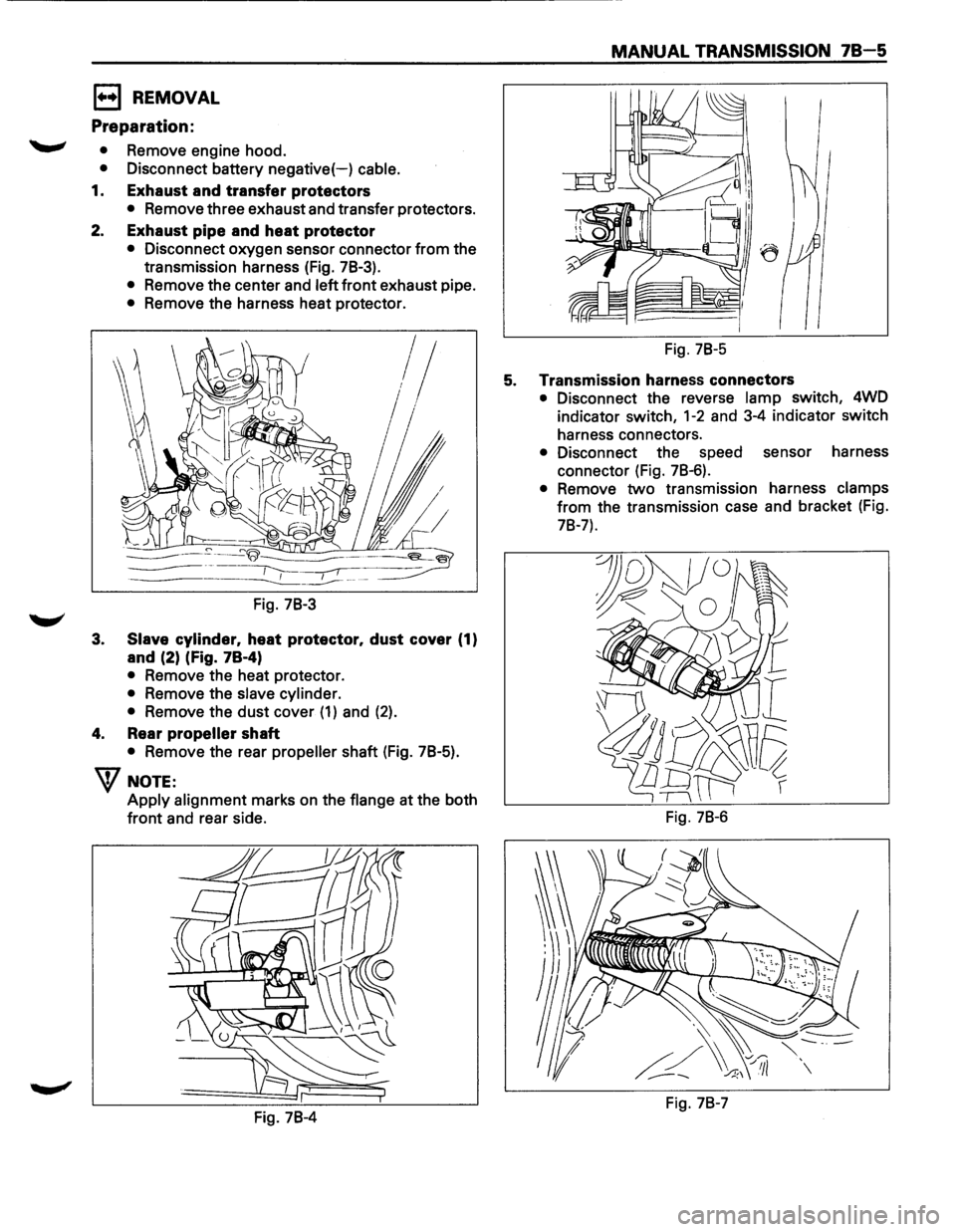
EJ REMOVAL
Preparation:
'--"' • Remove engine hood.
• Disconnect battery negative(-) cable.
1. Exhaust and transfer protectors
• Remove three exhaust and transfer protectors.
2. Exhaust pipe and heat protector
3.
• Disconnect oxygen sensor connector from the
transmission harness (Fig. 78-3).
• Remove the center and left front exhaust pipe.
• Remove the harness heat protector.
lj
Fig. 78-3
Slave cylinder, heat protector, dust cover (1)
and (2) (Fig. 78-4)
• Remove the heat protector.
• Remove the slave cylinder.
•
Remove the dust cover (1) and (2).
4. Rear propeller shaft
• Remove the rear propeller shaft (Fig. 78-5).
W NOTE:
Apply alignment marks on the flange at the both
front and rear side.
Fig. 78-4
MANUAL TRANSMISSION 78-5
Fig. 78-5
5. Transmission harness connectors
• Disconnect the reverse lamp switch, 4WD
indicator switch,
1-2 and 3-4 indicator switch
harness connectors.
• Disconnect the speed sensor harness
connector (Fig. 78-6).
• Remove two transmission harness clamps
from the transmission case and bracket (Fig.
78-7).
Fig. 78-6
Fig. 78-7
Page 1099 of 1928
12. Flywheel under cover bolts
• Install
three flywheel under cover bolts.
11. Gear control lever
• Install
the transmission control lever and
transfer
control lever.
• Install
the grommet assembly.
• Install
the front console assembly.
• Install
the gear control lever knob.
• Support the transfer case with a jack and then
remove the transmission jack
from
transmission side.
10. Front propeller shaft
• Install the front propeller shaft.
~~~ Torque N·m (lb·ft) 63 (46)
9. Front crossmember
• Install the front crossmember.
~~~ Torque N·m (lb·ft) 78 (58)
8. Engine rear mount
• Install the engine rear mount.
~~~ Torque N·m (lb·ft) 41 (30)
7. 3rd crossmember
• Install the 3rd crossmember.
1~1 Torque N-m (lb·ft) 50 (37)
6. Engine rear mount nuts
~~~ Torque N-m (lb·ft) 50 (37)
• Remove the transmission jack.
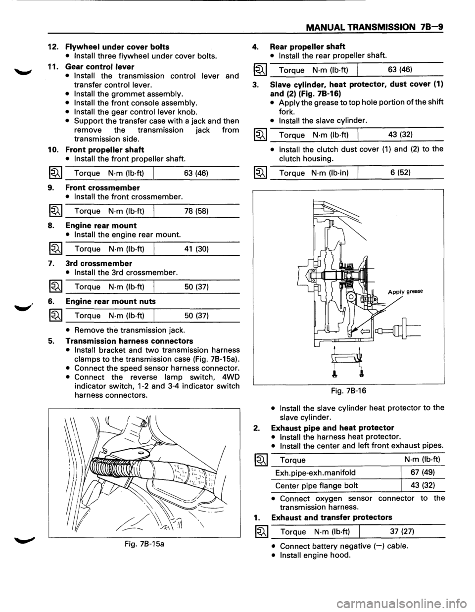
5. Transmission harness connectors
• Install bracket and two transmission harness
clamps to the transmission case (Fig. 78-15a).
• Connect the speed sensor harness connector.
• Connect the reverse lamp switch, 4WD
indicator
switch, 1-2 and 3-4 indicator switch
harness connectors.
Fig. 78-15a
MANUAL TRANSMISSION 78-9
4. Rear propeller shaft
• Install the rear propeller shaft.
I~I __ T_o_rq~u_e __ N_·m~(_lb_·ft~)~ _____ 6_3~(_46~) ____ _
3. Slave cylinder. heat protector. dust cover (1)
and (2) (Fig. 78-16)
• Apply the grease to top hole portion of the shift
fork.
• Install the slave cylinder.
~~~ Torque N·m (lb·ft) I 43 (32) _..:....__~----
• Install the clutch dust cover (1) and (2) to the
clutch housing.
~~~ Torque N·m (lb·in) 6 (52)
Apply grease
Fig. 78-16
• Install the slave cylinder heat protector to the
slave cylinder.
2. Exhaust pipe and heat protector
• Install the harness heat protector.
• Install the center and left front exhaust pipes.
~~~ Torque
Exh.pipe-exh.manifold
Center pipe
flange bolt N·m
(lb·ft)
67 (49)
43 (32)
• Connect oxygen sensor connector to the
transmission harness.
1. Exhaust and transfer protectors
~~~ Torque N·m (lb·ft) 37 (27)
• Connect battery negative (-) cable.
• Install
engine hood.
Page 1104 of 1928
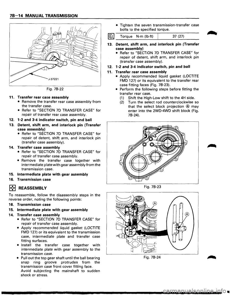
78-14 MANUAL TRANSMISSION
Fig. 78-22
11. Transfer rear case assembly
• Remove the transfer rear case assembly from
the transfer case.
• Refer to "SECTION 7D TRANSFER CASE" for
repair
of transfer rear case assembly.
12. 1-2 and 3-4 indicator switch, pin and ball
13. Detent, shift arm, and interlock pin (Transfer
case
assembly)
• Refer to "SECTION 7D TRANSFER CASE" for
repair of detent, shift arm, and interlock pin
(transfer case assembly).
14. Transfer case assembly
• Refer to "SECTION 7D TRANSFER CASE" for
repair
of transfer case assembly.
• Remove the transfer case together with
intermediate plate with gear assembly from the
transmission case.
15. Intermediate plate with gear assembly
16. Transmission case
l•!•l REASSEMBLY
To reassemble, follow the disassembly steps in the
reverse order, noting the following points:
16. Transmission case
15.
Intermediate plate with gear assembly
14. Transfer case assembly
• Refer to "SECTION 7D TRANSFER CASE" for
repair
of transfer case assembly.
• Apply recommended liquid gasket (LOCTITE
FMD 127) or its equivalent to the transmission
case, intermediate plate and transfer case
fitting surfaces.
• Install the transfer case together with
intermediate plate with gear assembly to the
transmission case.
• Pull out the top gear shaft until the ball bearing
snap ring groove protrudes
from the
transmission case
front cover fitting face.
Avoid subjecting the mainshaft
to sudden
shock
or stress.
• Tightem the seven transmission-transfer case
bolts
ito the specified torque.
I~I __ T_o_rq~u __ e __ N_·_m_(~lb_·f~t)~ ______ 3_7_(2_7~) ____ _
13. Detent, shift arm, and interlock pin (Transfer
case
assembly)
• Refer to "SECTION 7D TRANSFER CASE" for
repair of detent, shift arm, and interlock pin
(transfer case assembly).
12. 1-2 and 3-4 indicator switch, pin and ball
11. Transfe1· rear case assembly
• Apply recommended liquid gasket (LOCTITE
FMD 127) or its equivalent to the transfer rear
case fitting faces (Fig. 78-23).
• Perform the following steps before fitting the
transf13r rear case.
(1) Shift the High-Low shift to the 4H side.
(2) Turn the select rod counterclockwise so
that the select block projection ® may
enter into the 2WD-4WD shift block (Fig.
78-24).
Fig. 78-23
Fig. 78-24
•
Page 1162 of 1928
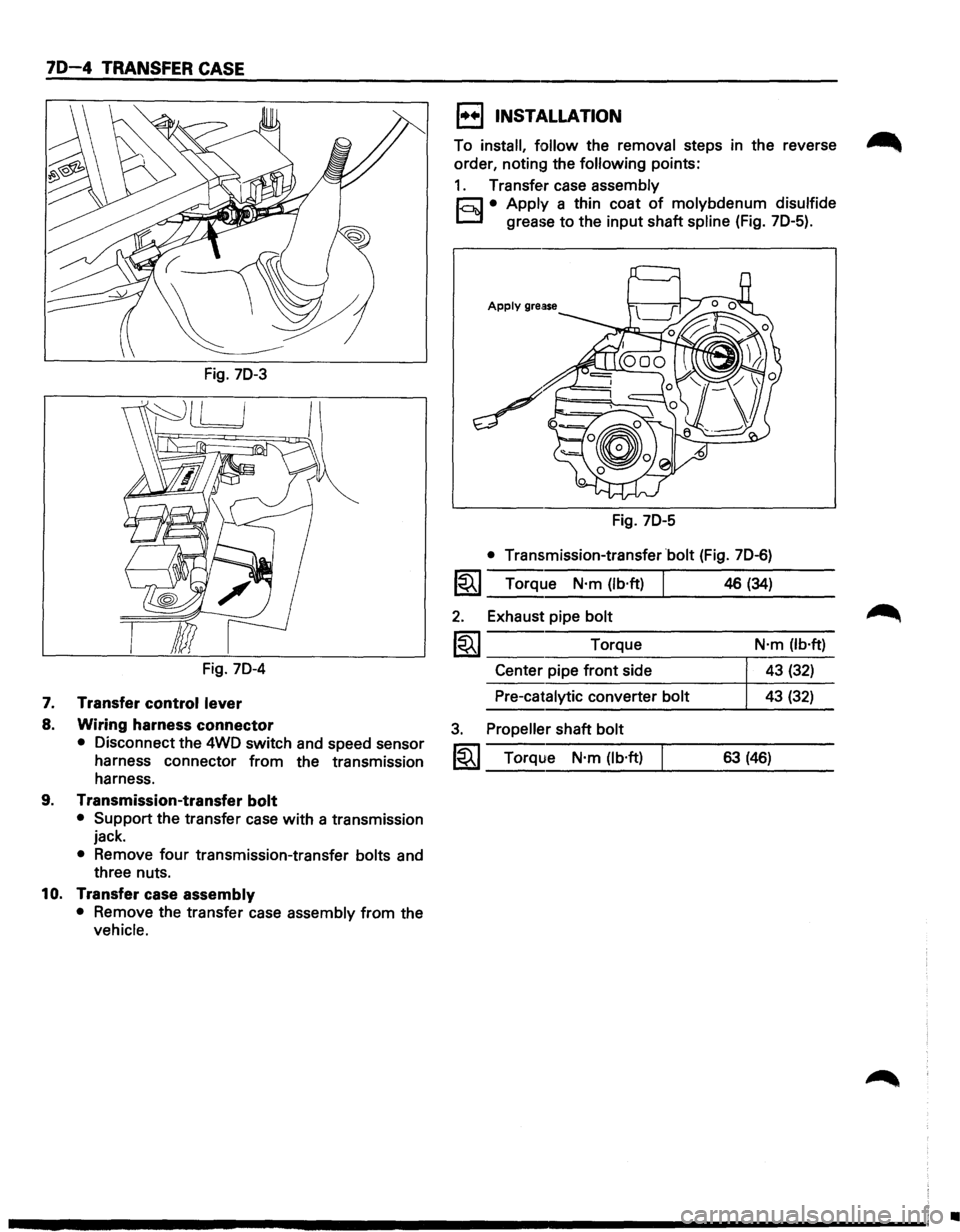
70-4 TRANSFER CASE
Fig. 70-3
Fig. 70-4
7. Transfer control lever
8. Wiring harness connector
• Disconnect the 4WD switch and speed sensor
harness connector from the transmission
harness.
9. Transmission-transfer bolt
• Support the transfer case with a transmission
jack.
• Remove four transmission-transfer bolts and
three nuts.
10. Transfer case assembly
• Remove the transfer case assembly from the
vehicle.
1••1 INSTALLATION
To install, follow the removal steps in the reverse ~
order, noting the following points:
1. Transfer case assembly
r;:;J • Apply a thin coat of molybdenum disulfide
D grease to the input shaft spline (Fig. 70-5).
Fig. 70-5
• Transmission-transfer bolt (Fig. 70-6)
1~1 Torque N·m (lb·ft)
2. Exhaust pipe bolt
1~1 Torque
Center pipe front side
Pre-catalytic converter bolt
3. Propeller shaft bolt
1~1 Torque N·m (lb·ft)
46 (34)
N·m (lb·ft)
43 (32)
43 (32)
63 (46)
•