ABS ISUZU TROOPER 1995 User Guide
[x] Cancel search | Manufacturer: ISUZU, Model Year: 1995, Model line: TROOPER, Model: ISUZU TROOPER 1995Pages: 1928
Page 135 of 1928
FRONT END ALIGNMENT 3A-3
ON-VEHICLE SERVICE
INSPECTION
Before making any adjustments affecting caster,
camber or toe-in, the following front end inspection
should be made.
I L•IINSPECT
1. Tires for proper inflation pressure. Refer to
"Wheels and Tires" in section 3E.
2. Front wheel bearings for proper adjustment.
Refer to "Front Wheel Drive" in section 4C.
3. Ball joints, tie rod ends and relay rods. If
excessive looseness is noted, correct before
adjusting. Refer
to "Steering Linkage" in section
3B3.
4. Wheel and tires for run-out. Refer to "Wheels
and Tires" in section 3E.
5. Trim height. If not within specifications, the
correction
must be made before adjusting caster.
6. Steering gear for looseness at the frame.
7. Shock absorbers for leaks or any noticeable
noise.
Refer
to "Front Suspension" in section 3C.
8. Control arms or stabilizer bar attachment for
looseness. Refer to "Front Suspension" in section
3C.
9. Alignment equipment. Follow the manufacturer's
instructions.
10. Level of the vehicle. The vehicle must be on a
level surface.
TRIM HEIGHT ADJUSTMENT
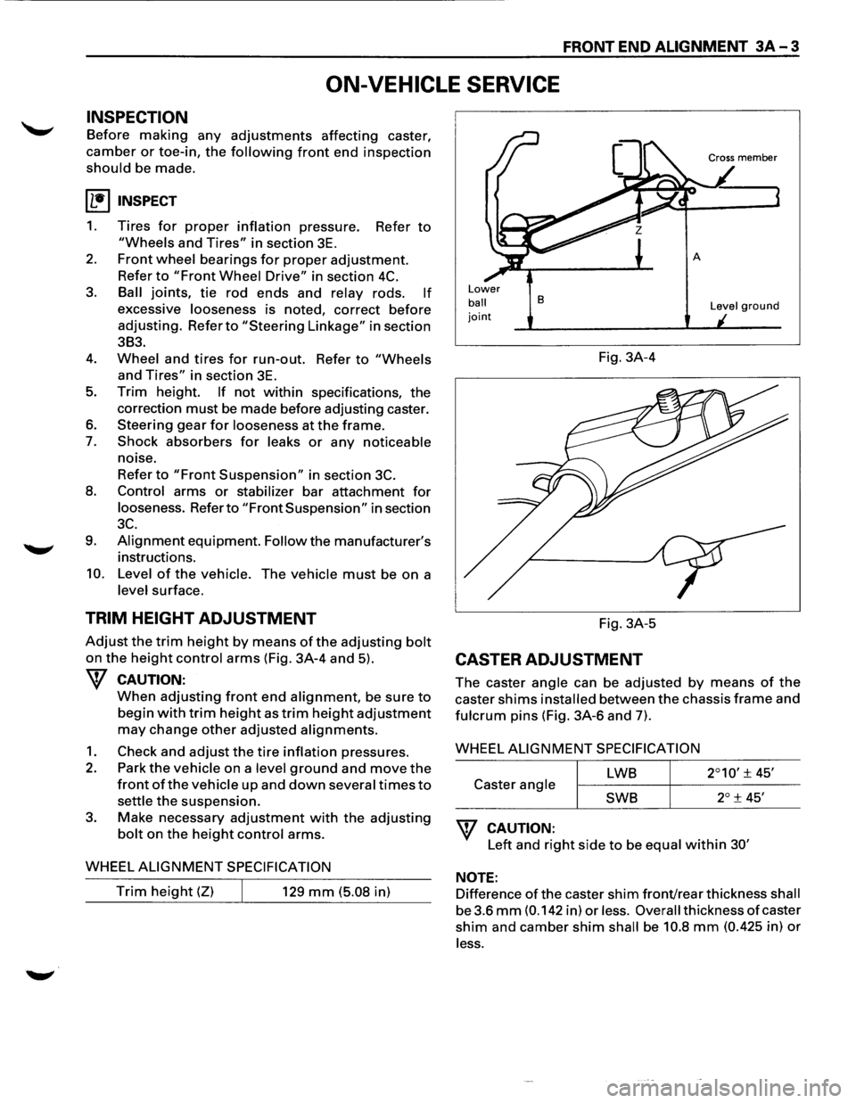
Adjust the trim height by means of the adjusting bolt
on the height control arms (Fig. 3A-4 and 5).
W CAUTION:
When adjusting front end alignment, be sure to
begin with trim height as trim height adjustment
may change other adjusted alignments.
1. Check and adjust the tire inflation pressures.
2. Park the vehicle on a level ground and move the
front of the vehicle up and down several times to
settle the suspension.
3. Make necessary adjustment with the adjusting
bolt on the height control arms.
WHEEL
ALIGNMENT SPECIFICATION
Trim height (Z) 129 mm (5.08 in)
Lower
ball joint
B
Fig. 3A-4
Fig. 3A-5
CASTER ADJUSTMENT
Level ground
The caster angle can be adjusted by means of the
caster shims installed between the chassis frame and
fulcrum pins (Fig. 3A-6 and 7).
WHEEL
ALIGNMENT SPECIFICATION
LWB
Caster angle
SWB
W CAUTION:
Left and right side to be equal within 30'
NOTE:
Difference of the caster shim front/rear thickness shall
be 3.6
mm (0.142 in) or less. Overall thickness of caster
shim and camber shim shall be 10.8 mm (0.425 in) or
less.
Page 165 of 1928
FRONT SUSPENSION 3C-1
SECTION 3C
FRONT SUSPENSION
'\f CAUTION:
When fasteners are removed, always reinstall them at the same location from which they were removed.
If a fastener needs to be replaced, use the correct part number fastener for that application. If the correct
part
number fastener is not available, a fastener of equal size and strength (or stronger) may be used.
Fasteners
that are not reused, and those requiring thread locking compound, will be called out. The correct
torque value must be used when installing fasteners that require it. If the above conditions are not
followed, parts or system damage could result.
Refer to section 3A in this manual for the wheel alignment procedure.
CONTENTS
General Description .. .. .. .. .. .. .. .. .. .. .. .. .. .. . 3C- 1
On-Vehicle Service .............................. 3C-3
Shock Absorber . . . . . . . . . . . . . . . . . . . . . . . . . . . . . . . 3C-3
Stabilizer Bar . .. .. . .. .. ..
.. . .. .. . .. .. .. . .. .. .. . 3C- 4
Torsion Bar
.................................... 3C-5
Knuckle . .
. . . . . . . . . . . . . . . . . . . . . . . . . . . . . . . . . . . . . . 3C-7
Upper
Control Arm ........................... 3C-10
Lower Control Arm ........................... 3C-13
Upper Ball Joint ............................... 3C- 16
Lower
Ball Joint ............................... 3C-18
Main Data and Specifications.................. 3C-20
General
Specifications . .
. . . . . . . . . . . . . . . . . . . . . 3C-
20
Torque Specifications ........................ 3C-21
Special Tools ..................................... 3C-22
GENERAL DESCRIPTION
The front suspension is designed to allow each wheel
to compensate for changes in the road surface level
without greatly affecting the opposite wheel. Each
wheel is independently connected to the frame by a
steering
knuckle, ball joint assemblies, and upper and
lower control arms. The front wheels are held in
proper relationship to each other by two outer track
rods
which are connected to steering arms on the
knuckles and to a center track rod.
All models have a front suspension system consisting
of control arms, stabilizer bar, shock absorber and a
torsion bar. The front end of the torsion bar is
attached
to the lower control arm. The rear of the
torsion bar is mounted into a height control arm at the
crossmember. Vehicle trim height is controlled by
adjusting this arm.
Shock absorbers are
mounted between the brackets
on the
frame and the lower control arms. The lower
portion of each shock absorber is attached to the
lower control arm by a bolt and nut. The upper portion
of each shock absorber extends through a frame
bracket and is secured with two rubber bushings,
three retainers and a nut.
Ball joint assemblies are bolted to the outer end of the
upper and lower control arm and are attached to the
steering
knuckle by nuts and cotter pins.
The
inner ends of the upper control arm have pressed
in bushings.
Bolts, passing through the bushing,
attach the control arm to the frame. The inner ends of
the lower control arm are attached to the frame by
bolts passing through the bushings, which are
pressed in the frame.
Side
roll of the front suspension is controlled by a
spring steel stabilizer bar. It is mounted in rubber
bushings, which are held to the crossmember by
brackets. The ends of the stabilizer bar are connected
to the lower control arms by links.
Page 167 of 1928
FRONT SUSPENSION 3C-3
ON-VEHICLE SERVICE
SHOCK ABSORBER
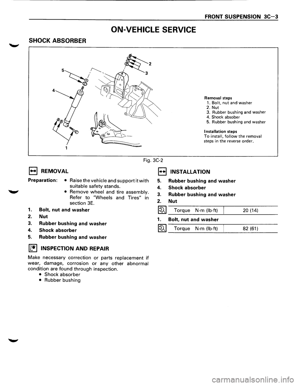
Fig. 3C-2
1••1 REMOVAL
Preparation: • Raise the vehicle and support it with
suitable safety stands.
'W' • Remove wheel and tire assembly.
Refer to "Wheels and Tires" in
section
3E.
1. Bolt, nut and washer
2. Nut
3. Rubber bushing and washer
4. Shock absorber
5. Rubber bushing and washer
IL'it'l INSPECTION AND REPAIR
Make necessary correction or parts replacement if
wear, damage, corrosion or any other abnormal
condition are found through inspection.
• Shock absorber
• Rubber bushing
EJ
5.
4.
3.
2.
~
1.
~
Removal steps
1.
Bolt, nut and washer 2. Nut
3. Rubber bushing and washer
4.
Shock absober 5. Rubber bushing and washer
Installation steps To install, follow the removal steps in the reverse order.
INSTALLATION
Rubber bushing and washer
Shock absorber
Rubber bushing and washer
Nut
Torque N-m (lb·ft) 20 (14)
Bolt, nut and washer
Torque N-m (lb·ft) 82 (61)
Page 176 of 1928
3C-12 FRONT SUSPENSION
NOTE:
Torque fulcrum pin nut after adjusting buffer clearance
(Fig. 3C-25)
I~EI Buffer clearance (T) mm (in) I 20 (0.79)
~~~ Torque N·m (lb·ft) I 108 (80)
Fig. 3C-25
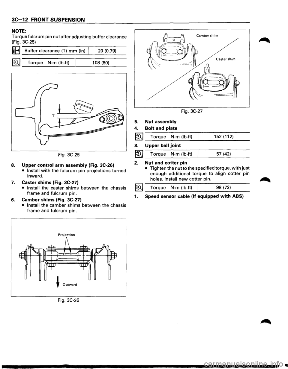
8. Upper control arm assembly (Fig. 3C-26)
• Install with the fulcrum pin projections turned
inward.
7. Caster shims (Fig. 3C-27)
• Install the caster shims between the chassis
frame and
fulcrum pin.
6. Camber shims (Fig. 3C-27)
• Install the camber shims between the chassis
frame and
fulcrum pin.
Projection
J Outward
Fig. 3C-26
Camber shim
Fig. 3C-27
5. Nut assembly
4. Bolt and plate
1~1 Torque N·m (lb·ft)
3. Upper ball joint
~~~ Torque N·m (lb·ft)
2. Nut and cotter pin
152 (112)
57 (42)
• Tighten the nut to the specified torque, with just
enough
additional torque to align cotter pin
holes. Install new cotter pin.
1~1 Torque N·m (lb·ft) I 98 (72)
1. Speed sensor cable (If equipped with ABS)
•
Page 177 of 1928
FRONT SUSPENSION 3C-13
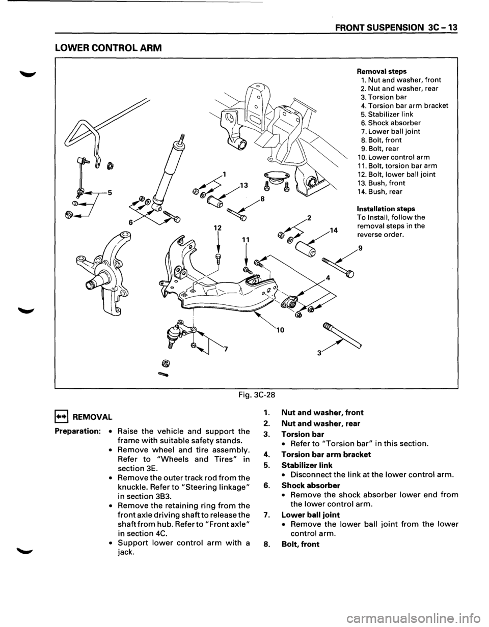
LOWER CONTROL ARM
Removal steps
1. Nut and washer, front
2. Nut and washer, rear
3. Torsion bar
4. Torsion bar arm bracket
5. Stabilizer link
6. Shock absorber
7. Lower ball joint
8. Bolt, front
9. Bolt, rear
10. Lower control arm
11. Bolt, torsion bar arm
12. Bolt, lower ball joint
13. Bush, front
14. Bush, rear
Installation steps
2 To
Install, follow the
14
removal steps in the
Qj ~ ';ve"'e mde,.
;<
~7
10
Fig. 3C-28
1••1 REMOVAL
Preparation: • Raise the vehicle and support the
frame with suitable safety stands.
• Remove wheel and tire assembly.
Refer to "Wheels and Tires" in
section 3E.
• Remove the outer track rod from the
knuckle. Refer to "Steering linkage"
in section 383.
• Remove the retaining ring from the
front axle driving shaft to release the
shaft from hub. Refer to "Front axle"
in section 4C.
• Support lower control arm with a
jack.
1. Nut and washer, front
2. Nut and washer, rear
3. Torsion bar
• Refer to "Torsion bar" in this section.
4. Torsion bar arm bracket
5. Stabilizer link
• Disconnect the link at the lower control arm.
6. Shock absorber
• Remove the shock absorber lower end from
the lower control arm.
7. Lower ball joint
• Remove the lower ball joint from the lower
control arm.
8. Bolt, front
Page 179 of 1928
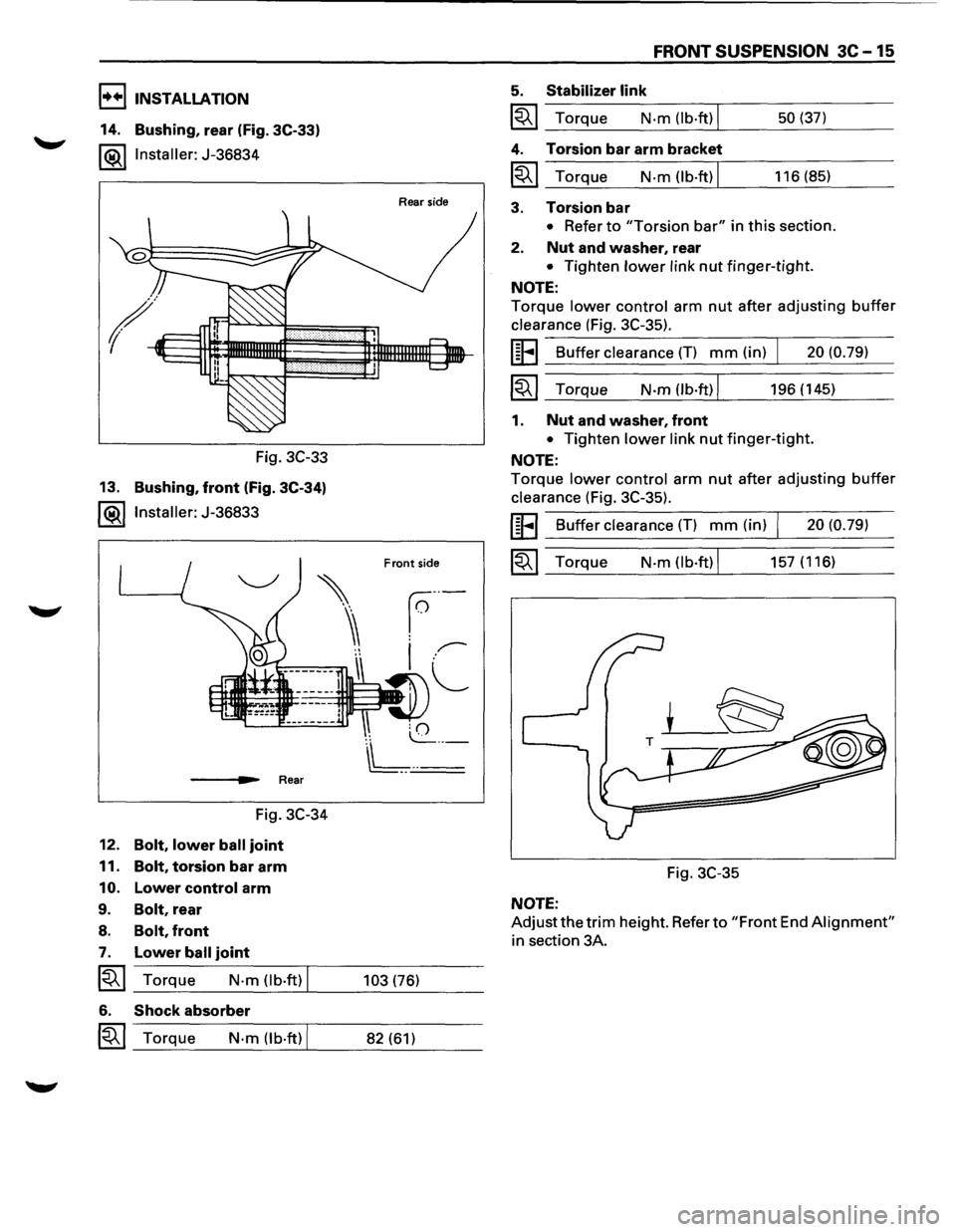
I••IINSTALLATION
14. Bushing, rear (Fig. 3C-33)
l®.llnstaller: J-36834
Fig. 3C-33
13.
Bushing, front (Fig. 3C-34)
l®llnstaller: J-36833
___ ..,._. Rear
Fig. 3C-34
12.
Bolt, lower ball joint
11. Bolt, torsion bar arm
10. Lower control arm
9. Bolt, rear
8. Bolt, front
7. Lower ball joint
~~~ Torque N-m (lb·ft) I
6. Shock absorber
~~~ Torque N-m (lb·ft) I
Rear side
Front side
103 (76)
82 (61)
FRONT SUSPENSION 3C-15
5. Stabilizer link
~~~ Torque N·m (lb·ft) I
4. Torsion bar arm bracket
~~~ Torque N-m (lb.ft) I
3. Torsion bar
50 (37)
116 (85)
• Refer to "Torsion bar" in this section.
2. Nut and washer, rear
• Tighten lower link nut finger-tight.
NOTE:
Torque lower control arm nut after adjusting buffer
clearance (Fig. 3C-35).
UFI Buffer clearance (T) mm (in) I 20 (0.79)
~~~ Torque N-m(lb·ft)l 196(145)
1. Nut and washer, front
• Tighten lower link nut finger-tight.
NOTE:
Torque lower control arm nut after adjusting buffer
clearance (Fig. 3C-35).
UFI Buffer clearance (T) mm (in) I 20 (0.79)
~~~ Torque N-m (lb·ft) I 157 (116)
Fig. 3C-35
NOTE:
Adjustthetrim height. Refer to "Front End Alignment"
in section 3A.
Page 184 of 1928
3C-20 FRONT SUSPENSION
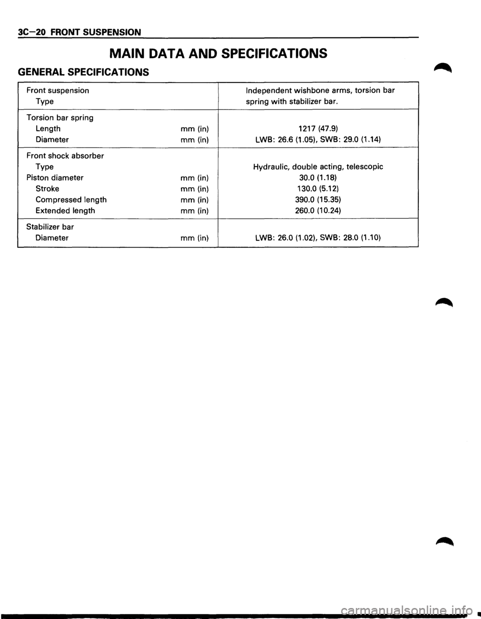
MAIN DATA AND SPECIFICATIONS
GENERAL SPECIFICATIONS
Front suspension Independent wishbone arms, torsion bar
Type spring
with stabilizer bar.
Torsion bar spring
Length
mm (in) 1217
(47.9)
Diameter
mm (in) LWB: 26.6 (1.05), SWB: 29.0 (1.14)
Front shock absorber
Type
Hydraulic, double acting, telescopic
Piston diameter mm (in) 30.0 (1.18)
Stroke
mm (in) 130.0 (5.12)
Compressed
length mm (in) 390.0 (15.35)
Extended
length mm (in) 260.0 (1 0.24)
Stabilizer
bar
Diameter
mm (in) LWB: 26.0 (1.02),
SWB: 28.0 (1.10)
•
Page 187 of 1928
REAR SUSPENSION 30-1
SECTION 30
REAR SUSPENSION
WCAUTION:
VI When fasteners are removed, always reinstall them at the same location from which they were removed. If a
fastener needs to be
replaced, use the correct part number fastener for that application. If the correct part
number fastener is
not available, a fastener of equal size and strength (or stronger) may be used. Fasteners
that are
not reused, and those requiring thread locking compound, will be called out. The correct torque
value must be used when installing fasteners that require it. If the above conditions are not followed, parts or
system damage could result.
CONTENTS
General Description . . . . . . . . . . . . . . . . . . . . 3D-2
On-Vehicle Service .................... 3D-3
Coil Spring . .
. . . . . . . . . . . . . . . . . . . . . . . 3D· 3
Shock
Absorber . . . . . . . . . . . . • . . . . . . . . 3D-5
Trailing Link . .
. . . . . . . . . . . . . . . . . . . . . . 3D-6
Center
Link . . • . . . . . . . . . . • . . . . . . . . . . . 3D-8
Lateral Rod ......................... 3D-1 0
Stabilizer Bar ........................ 3D-11
Main Data and Specifications ............ 3D-12
General Specifications ................ 3D-12
Torque Specifications
................ 30-13
Special Tools .......................... 3D-13
Page 188 of 1928
30-2 REAR SUSPENSION
GENERAL DESCRIPTION
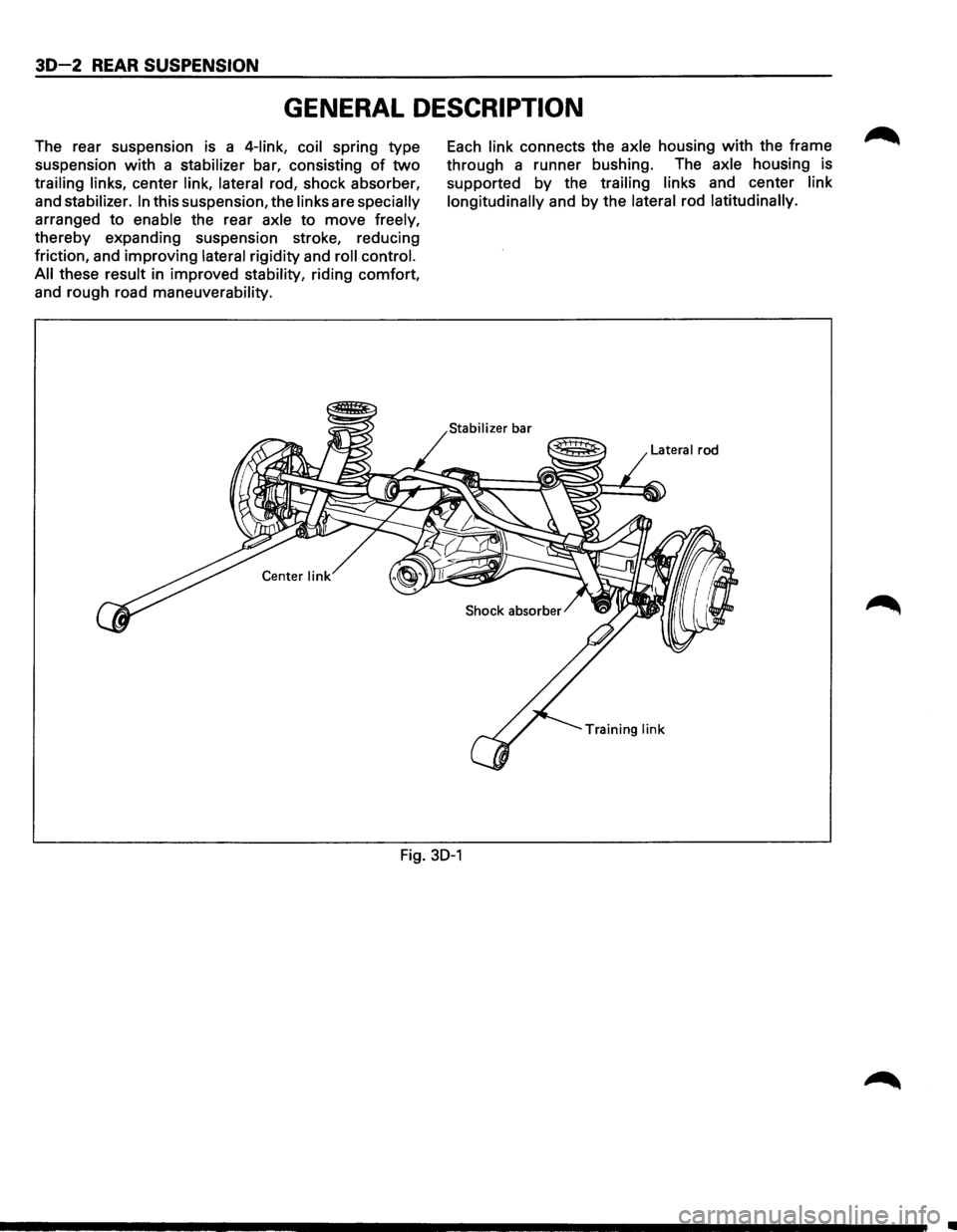
The rear suspension is a 4-link, coil spring type
suspension
with a stabilizer bar, consisting of two
trailing links, center link, lateral rod, shock absorber,
and
stabilizer. In this suspension, the links are specially
arranged to enable the rear axle to move freely,
thereby expanding suspension stroke, reducing
friction, and improving
lateral rigidity and roll control.
All
these result in improved stability, riding comfort,
and rough road
maneuverability.
Each link connects the axle housing with the frame
through a runner bushing. The
axle housing is
supported
by the trailing links and center link
longitudinally
and by the lateral rod latitudinally.
Lateral rod
Training
link
Fig. 30-1
•
Page 189 of 1928
REAR SUSPENSION 30-3
ON-VEHICLE SERVICE
COIL SPRING
3
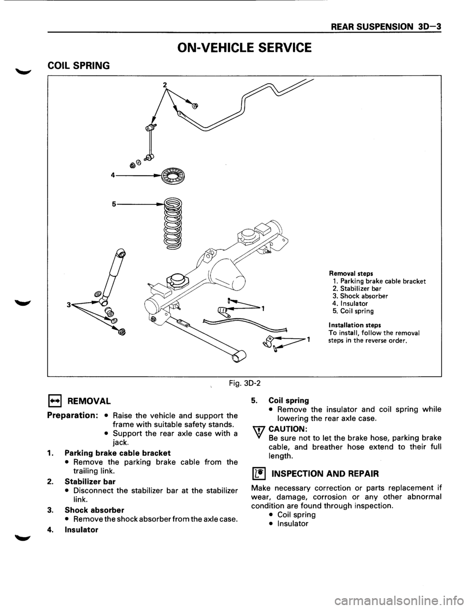
Removal steps
1. Parking brake cable bracket 2. Stabilizer bar
3. Shock absorber
4. Insulator 5. Coil spring
Installation steps
To install,
follow the removal
steps in the reverse order.
Fig. 30-2
E) REMOVAL
Preparation: • Raise the vehicle and support the
frame
with suitable safety stands.
• Support the rear axle case with a
jack.
1. Parking brake cable bracket
• Remove the parking brake cable from the
trailing link.
2. Stabilizer bar
• Disconnect the stabilizer bar at the stabilizer
link.
3. Shock absorber
• Remove the shock absorber from the axle case.
4. Insulator
5. Coil spring
• Remove the insulator and coil spring while
lowering
the rear axle case.
U7 CAUTION:
VI Be sure not to let the brake hose, parking brake
cable, and breather hose extend to their full
length.
(L!] INSPECTION AND REPAIR
Make necessary correction or parts replacement if
wear, damage, corrosion or any other abnormal
condition are found through inspection.
• Coil spring
• Insulator