light ISUZU TROOPER 1995 Workshop Manual
[x] Cancel search | Manufacturer: ISUZU, Model Year: 1995, Model line: TROOPER, Model: ISUZU TROOPER 1995Pages: 1928
Page 22 of 1928
OB-6 MAINTENANCE AND LUBRICATION
BRAKE SYSTEMS OPERATION
Watch for the "BRAKE" light coming on. Other
signs of possible brake trouble are such things as
repeated pulling to one side when braking, unusual
sounds
when braking or between brake
applications,
or increased brake pedal travel. If you
note one of these conditions, repair the system at
once.
For convenience, the
following should be done
when wheels are removed for rotation: Inspect lines
and hoses
for proper hookup, bindings, leaks, crack,
chafing etc.
Inspect disc brake pads for wear and
rotors
for surface condition.
Inspect other brake parts, including parking brake
drums, linings etc., at the same time. Check parking
brake adjustment.
Inspect brakes more often if habit or
conditions
result in frequent braking.
PARKING BRAKE AND TRANSMISSION
PARK MECHANISM OPERATION
Park on a fairly steep hill and hold the vehicle with
the parking brake only. This checks holding ability.
On
automatic transmission vehicles, shifting from
"P" position to the other positions cannot be made
unless
the brake pedal is depressed when the key
switch is in
"ON" position or the engine running.
WARNING
•
Before checking starter safety switch
operation below,
be sure to have enough
room around the
vehicle. Then firmly apply
both the parking brake and the regular brake.
Do not
use the accelerator pedal. If the engine
starts, be ready
to turn off the key promptly.
Take these precautions because the vehicle
could move
without warning and possibly
cause personal injury
or property damage.
STARTER SAFETY SWITCH OPERATION
(AUTOMATIC TRANSMISSION)
Check by trying to start the engine in each gear
while setting the parking brake and the foot brake.
The starter
should crank only in "P" (Park) or "N"
(Neutral).
STARTER SAFETY SWITCH OPERATION
(MANUAL TRANSMISSION)
To check, place the shift lever in "Neutral", push
the clutch pedal halfway and try to start. The starter
should not crank. The starter should crank only
when the clutch pedal is fully depressed.
ACCELERATOR LINKAGE LUBRICATION
Lubricate the accelerator pedal fulcrum pin with
chassis grease.
STEERING AND SUSPENSION
INSPECTION
Inspect front and rear suspension and steering
system
for damaged, loose or missing parts or signs
of wear. Inspect power steering lines and hoses for
proper hookup, binding, leaks, cracks, chafing, etc.
BODY AND CHASSIS LUBRICATION
Lubricate the key lock cylinders, the hood latch, the
hood and door hinges, the door check link, the
parking cable guides,
the underbody contact points,
and the linkage.
PROPELLER SHAFT INSPECTION AND
LUBRICATION
Lubricate sliding yoke and universal joints with
grease containing MOS2 (disulfide molybdenum
type grease) at the interval shown in the
Maintenance Schedule. Check for play in normal
direction of rotation of sliding yoke and universal
joints. Also check
propeller shaft flange-to-pinion
bolts for proper torque of 63 N·m (46 lb·ft) for front
and rear propeller shaft.
AUTOMATIC TRANSMISSION FLUID
INSPECTION
Check the lubricant level every 7,500 miles (12,000
km) and add lubricant
if necessary.
Under harsh operating conditions, such as constant
driving in heavy city traffic during
hot weather, or in
hilly or mountainous terrain, change the transmission
fluid and service the
sump filter after every 20,000
miles (32,000 km) of operation.
AUTO CRUISE CONTROL INSPECTION
Check to see if the clearance between cruise link and
accelerator is normal. Also check that the vacuum
hoses are routed and connected properly.
CLUTCH LINES AND HOSES INSPECTION
Check lines and hoses for proper attachment,
binding, leaks, cracks, chafing, deterioration, etc.
Any questionable parts should be replaced or
repaired at once. When abrasion or wear is evident
on lines or hoses, the cause must be corrected.
..
Page 58 of 1928
1 B - 4 AIR CONDITIONING
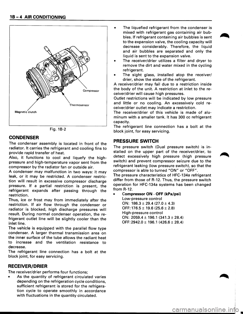
Compressor
Thermosensor
Magnetic clutch
Fig. 18-2
CONDENSER
The condenser assembly is located in front of the
radiator. It carries the refrigerant and cooling fins to
provide rapid transfer of heat.
Also, it functions to cool and liquefy the high
pressure and high-temperature vapor sent from the
compressor by the radiator fan or outside air.
A condenser
may malfunction in two ways: it may
leak, or it may be restricted. A condenser restric
tion will result in excessive compressor discharge
pressure.
If a partial restriction is present, the
refrigerant expands after passing through the
restriction.
Thus, ice
or frost may from immediately after the
restriction. If air flow through the condenser or
radiator is blocked, high discharge pressures will
result. During normal condenser operation, the re
frigerant outlet line will be slightly cooler than the
inlet line.
The vehicle is equipped with the parallel flow type
condenser. A larger thermal transmission area on
the inner surface of the tube allows the radiant heat
to increase and the ventilation resistance to
decrease.
The
refrigerant line connection has a bolt at the
block joint, for easy servicing.
RECEIVER/DRIER
The receiver/drier performs four functions;
• As the quantity of refrigerant circulated varies
depending on the refrigeration cycle conditions,
sufficient refrigerant is stored for the refrigera
tion cycle to operate smoothly in accordance
with fluctuations in the quantity circulated. •
The liquefied refrigerant from the condenser
is
mixed with refrigerant gas containing air bub
bles. If refrigerant containing air bubbles is sent
to the expansion valve, the cooling capacity will
decrease considerably. Therefore, the liquid
and air bubbles are separated and only the
liquid is sent to the expansion valve.
•
The receiver/drier utilizes a filter and dryer to
remove the dirt and water mixed in the cycling
refrigerant.
• The sight glass, installed atop the receiver/
drier, show the state of the refrigerant.
A receiver/drier may fail due to a restriction inside
the body of the unit. A restriction at inlet to the re
ceiver/drier
will cause high pressures.
Outlet restrictions will be indicated by low pressure
and
little or no cooling. An excessively cold re
ceiver/drier
outlet may indicate a restriction.
The receiver/drier
of this vehicle is made of alu
minum with a smaller tank. It has 300 cc refrigerant
capacity.
The
refrigerant line connection has a bolt at the
block joint, for easy servicing.
PRESSURE SWITCH
The pressure switch (Dual pressure switch) is in
stalled on the upper part of the receiver/drier, to
detect excessively high pressure (high pressure
switch) and prevent compressor seizure due to the
refrigerant leaking (low pressure switch), so that the
compressor is able to turned "ON" or "OFF".
The pressure characteristics of HFC-134a refrigerant
differ from those of R-12. Thus, the pressure switch
operation for HFC-134a systems has been changed
from R-12.
• Compressor ON · OFF (kPa/psi)
Low-pressure control
ON: 186.3 ± 29.4 (27.0 ± 4.3)
OFF: 176.5 ± 19.6 (25.6 ± 2.8)
High-pressure
control
ON: 2059.4 ± 196.1 (341.3 ± 28.4)
OFF: 2942.0 ± 196.1 (426.6 ± 28.4)
Page 77 of 1928
6.
7.
Perform system leak test.
• Charge the system with approx. 200 g (0.44
lbs) of HFC-134a.
• Make sure the high pressure valve of the
manifold gauge is closed.
• Check
to ensure that the degree of pressure
does
not change.
• Check for refrigerant leaks by using a HFC-
134a leak detector.
• If a leak occurs, recover the refrigerant. Repair
the leak, and start all over again from the first
step of evacuation.
If no leaks are found, continue charging re
frigerant to the air conditioning system.
• Charge the refrigerant until the scale reading
decreases
by the amount of the charge
specified.
Specified
amount g (lbs.) I 750 (1.65)
• If charging the system becomes difficult:
( 1) Run the engine at idle and close all the
vehicle doors.
(2) Turn A!C switch "ON".
(3) Set the fan switch to its highest position.
(4) Set air source selector lever to "CIRC".
(5) Slowly open the low side valve on the
manifold gauge set.
WARNING: BE ABSOLUTELY SURE NOT TO
OPEN THE HIGH PRESSURE VALVE OF THE
MANIFOLD GAUGE. SHOULD THE HIGH
PRESSURE VALVE BE OPENED, THE HIGH
PRESSURE REFRIGERANT WOULD FLOW
BACKWARD, AND
THIS MAY CAUSE THE
REFRIGERANT CONTAINER TO BURST.
8. When finished with the refrigerant charging,
close the low pressure valve of the manifold
gauge and container valve.
9. Check for refrigerant leaks.
AIR CONDITIONING 18 -23
Checking
the A/C system
1. Run the engine and close all the vehicle doors.
2. Turn A!C switch "ON", set the fan switch to its
highest position, set air source
lever to "CIRD"
and set temperature lever to full cool position.
3. Check the high and low pressure of the manifold
gauge.
• Immediately after charging refrigerant, both
high and low pressure are slightly high, but
they settle down to the pressure guidelines
shown below:
Ambient temperature: 25-30°C (77 -86°F)
Pressure guidelines:
• High-pressure side;
Approx. 1372.9-1863.3kPa (199.1-270.2psi)
• Low-pressure side;
Approx. 147.1-294.2 kPa (21.3-42.7 psi)
• If an abnormal pressure is found, refer to
"CHECKING REFRIGERANT SYSTEM WITH
MANIFOLD
GAUGE" in this section.
4. Put your hand in front of the air outlet and move
the temperature control lever of the control
panel
to different positions. Check if the outlet
temperature changes as selected by the control
knob.
Page 104 of 1928
28-2 BUMPERS
FRONT BUMPER
ON-VEHICLE SERVICE
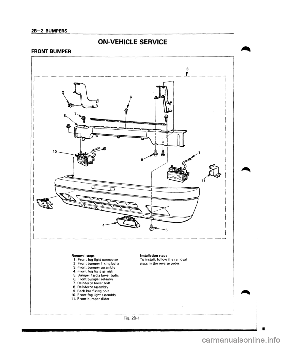
Removal steps 1. Front fog llght connector 2. Front bumper fixing bolts 3. Front bumper assembly 4. Front fog light garnish
5. Bumper fascia lower bolts 6. Front bumper retainer 7. Reinforce lower bolt 8. Reinforce assembly
9. Back bar fixing bolt
10. Front fog light assembly 11. Front bumper slider
Fig. 2B-1
Installation steps To install, follow the removal steps in the reverse order.
•
Page 105 of 1928
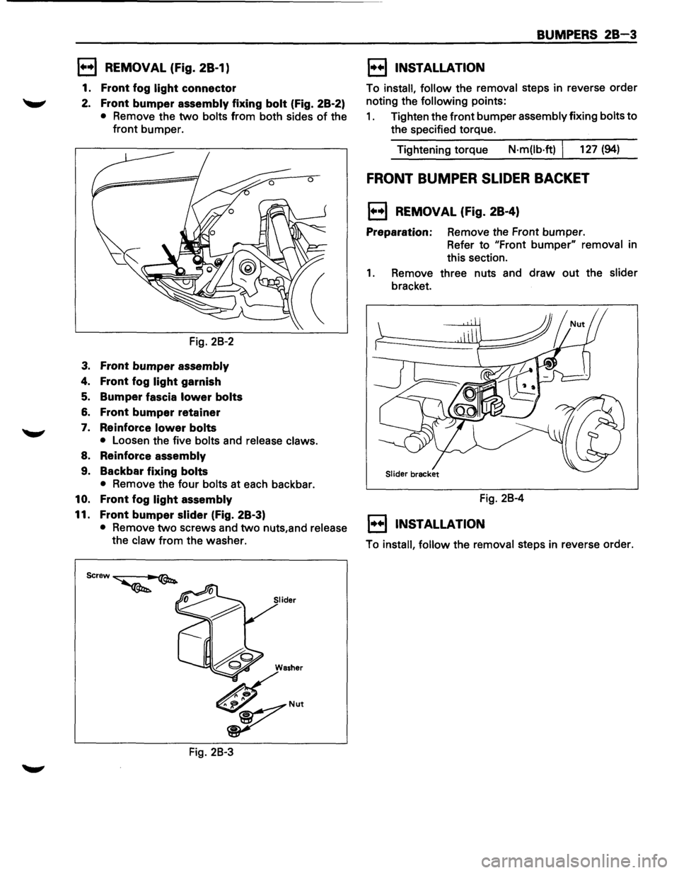
1••1 REMOVAL (Fig. 28-1)
1. Front fog light connector
2. Front bumper assembly fixing bolt (Fig. 28-2)
• Remove the two bolts from both sides of the
front bumper.
Fig. 28-2
3. Front bumper assembly
4. Front fog light garnish
5. Bumper fascia lower bolts
6. Front bumper retainer
7. Reinforce lower bolts
• Loosen the five bolts and release claws.
8. Reinforce assembly
9. Backbar fixing bolts
• Remove the four bolts at each backbar.
10. Front fog light assembly
11. Front bumper slider (fig. 28-3)
• Remove two screws and two nuts,and release
the claw from the washer.
Fig. 28-3
BUMPERS 28-3
1••1 INSTALLATION
To install, follow the removal steps in reverse order
noting the
following points:
1. Tighten the front bumper assembly fixing bolts to
the specified torque.
Tightening torque
N·m(lb·ft) I 127 (94)
FRONT BUMPER SLIDER BACKET
1••1 REMOVAL (Fig. 28-4)
Preparation: Remove the Front bumper.
Refer to "Front
bumper" removal in
this section.
1. Remove three nuts and draw out the slider
bracket.
Fig. 28-4
1••1 INSTALLATION
To install, follow the removal steps in reverse order.
Page 125 of 1928
DIAGNOSIS 3-5
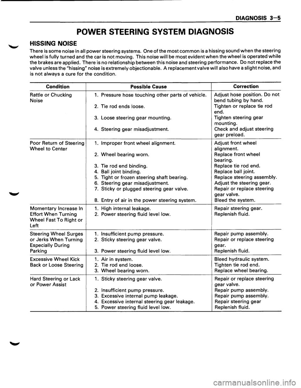
POWER STEERING SYSTEM DIAGNOSIS
HISSING NOISE
There is some noise in all power steering systems. One of the most common is a hissing sound when the steering
wheel is fully turned and the car is not moving. This noise will be most evident when the wheel is operated while
the brakes are applied. There is no relationship between this noise and steering performance. Do not replace the
valve unless the "hissing" noise is extremely objectionable. A replacement valve will also have a slight noise, and
is
not always a cure for the condition.
Condition
Possible Cause Correction
Rattle or Chucking 1. Pressure
hose touching other parts of vehicle. Adjust hose position. Do not
Noise bend
tubing by hand.
2. Tie rod ends loose. Tighten or replace tie rod
end.
3. Loose steering gear mounting. Tighten
steering gear
mounting.
4. Steering gear misadjustment. Check and adjust steering
gear
preload.
Poor Return of Steering 1. Improper front wheel alignment. Adjust front wheel
Wheel
to Center alignment.
2. Wheel bearing worn. Replace front wheel
bearing.
3. Tie rod end binding. Replace tie rod end.
4. Ball joint binding. Replace ball joint.
5. Tight or frozen steering shaft bearing. Replace steering assembly.
6. Steering gear misadjustment. Adjust the steering gear.
7. Sticky or plugged steering gear valve. Repair or replace steering
gear
valve.
8. Entry of air in the power steering system. Bleed the system.
Momentary Increase In 1. High internal leakage. Repair steering gear.
Effort When Turning
2. Power steering fluid level low. Replenish
fluid.
Wheel
Fast To Right or
Left
Steering
Wheel Surges 1. Insufficient pump pressure. Repair pump assembly.
or Jerks
When Turning 2. Sticky steering gear valve. Repair or replace steering
Especially During gear.
Parking
3. Power steering fluid level low. Replenish
fluid.
Excessive Wheel Kick 1. Air in system. Bleed hydraulic system.
Back
or Loose Steering 2. Tie rod end loose. Tighten tie rod end.
3. Wheel bearing worn. Replace wheel bearing.
Hard Steering
or Lack 1. Sticky steering gear valve. Repair or replace steering
or Power Assist gear valve.
2. Insufficient pump pressure.
Repair pump assembly.
3. Excessive internal pump leakage. Repair
pump assembly.
4. Excessive internal steering gear leakage. Repair steering gear
5. Power steering fluid level low. Replenish
fluid.
Page 128 of 1928
3-8 DIAGNOSIS
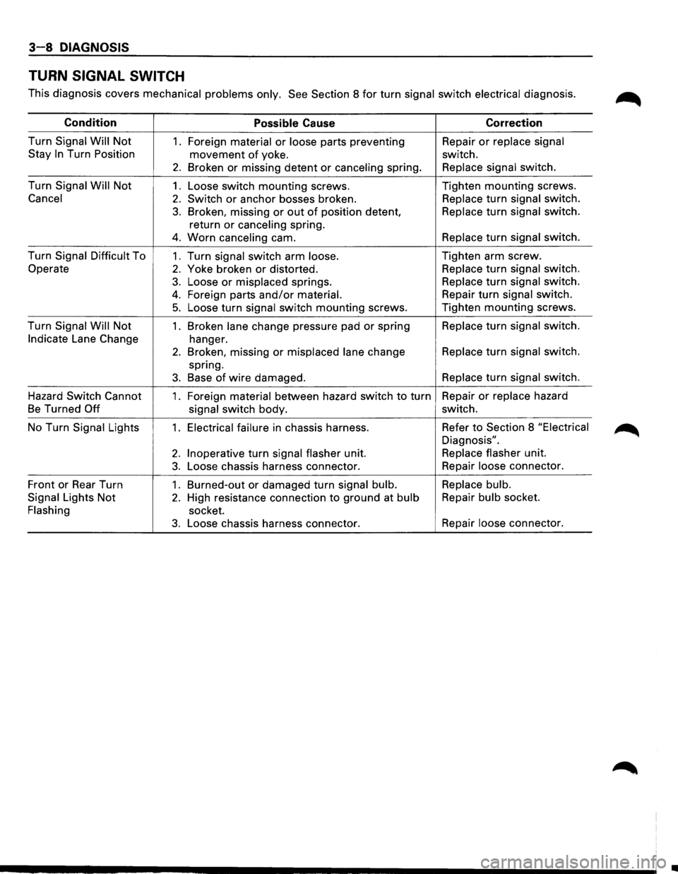
TURN SIGNAL SWITCH
This diagnosis covers mechanical problems only. See Section 8 for turn signal switch electrical diagnosis. ~
Condition Possible Cause Correction
Turn Signal
Will Not 1. Foreign material or loose parts preventing Repair or replace
signal
Stay
In Turn Position movement of yoke. switch.
2. Broken or missing detent or canceling spring. Replace
signal switch.
Turn Signal
Will Not 1. Loose switch mounting screws. Tighten mounting screws.
Cancel
2. Switch or anchor bosses broken. Replace
turn signal switch.
3. Broken, missing or out of position detent, Replace
turn signal switch.
return
or canceling spring.
4. Worn canceling cam. Replace
turn signal switch.
Turn Signal Difficult To
1. Turn signal switch arm loose. Tighten
arm screw.
Operate
2. Yoke broken or distorted. Replace
turn signal switch.
3. Loose or misplaced springs. Replace
turn signal switch.
4. Foreign parts and/or material. Repair
turn signal switch.
5. Loose turn signal switch mounting screws. Tighten mounting screws.
Turn Signal Will Not
1 . Broken lane change pressure pad or spring Replace
turn signal switch.
Indicate Lane Change
hanger.
2. Broken, missing or misplaced lane change Replace
turn signal switch.
spring.
3. Base of wire damaged. Replace
turn signal switch.
Hazard Switch Cannot
1. Foreign material between hazard switch to turn Repair
or replace hazard
Be Turned Off
signal switch body. switch.
No Turn Signal Lights
1. Electrical failure in chassis harness. Refer to Section
8 "Electrical
Diagnosis".
2. Inoperative turn signal flasher unit. Replace
flasher unit.
3. Loose chassis harness connector. Repair
loose connector.
Front or Rear Turn
1. Burned-out or damaged turn signal bulb. Replace
bulb.
Signal Lights
Not 2. High resistance connection to ground at bulb Repair
bulb socket.
Flashing socket.
3. Loose chassis harness connector. Repair
loose connector.
•
Page 134 of 1928
3A-2 FRONT END ALIGNMENT
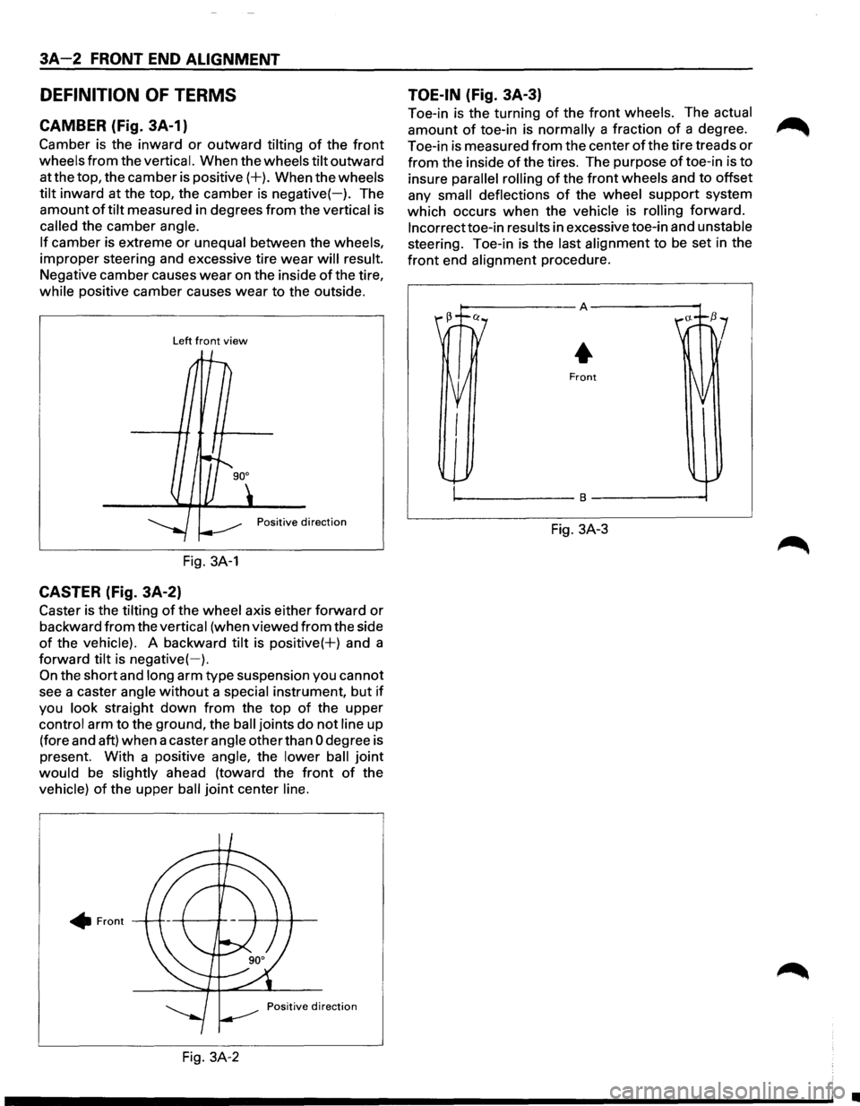
DEFINITION OF TERMS
CAMBER (Fig. 3A-1)
Camber is the inward or outward tilting of the front
wheels from the vertical. When the wheels tilt outward
at the top, the camber is
positive(+). When the wheels
tilt inward at the top, the camber is negative(-). The
amount
of tilt measured in degrees from the vertical is
called the camber angle.
If camber is extreme or unequal between the wheels,
improper steering and excessive tire
wear will result.
Negative camber causes
wear on the inside of the tire,
while positive camber causes wear to the outside.
Left front view
Positive direction
Fig. 3A-1
CASTER (Fig. 3A-2)
Caster is the tilting of the wheel axis either forward or
backward from the vertical (when viewed from the side
of the vehicle). A backward tilt is positive(+) and a
forward tilt is
negative(-).
On the short and long arm type suspension you cannot
see a caster angle
without a special instrument, but if
you look straight down from the top of the upper
control arm to the ground, the
ball joints do not line up
(fore and aft) when a caster angle other than
0 degree is
present. With a positive angle, the lower
ball joint
would be slightly ahead (toward the front of the
vehicle)
of the upper ball joint center line .
• Front
Fig. 3A-2
TOE-IN (Fig. 3A-3)
Toe-in is the turning of the front wheels. The actual
amount of toe-in is normally a fraction of a degree.
Toe-in is measured
from the center of the tire treads or
from the inside of the tires. The purpose of toe-in is to
insure
parallel rolling of the front wheels and to offset
any
small deflections of the wheel support system
which occurs
when the vehicle is rolling forward.
lncorrecttoe-in results in excessive toe-in and unstable
steering. Toe-in is the last alignment to
be set in the
front end alignment procedure.
Fig. 3A-3
•
Page 142 of 1928
381 - 4 POWER STEERING GEAR AND PUMP
ON-VEHICLE SERVICE
MAINTENANCE
The hydraulic system should be kept clean and fluid
level in the reservoir should be checked at regular
intervals
and fluid added when required. Refer to
"MAINTENANCE AND LUBRICATION" in section OB
ofthe manual for type offluid to be used and intervals
for filling.
If the system contains some dirt, flush it as detailed
later
in this section. If it is exceptionally dirty, both the
pump and the gear must be completely disassembled
before further usage.
All tubes, hoses, and fittings should be inspected for
leakage at regular intervals. Fittings must be tight.
Make sure the clips, clamps and supporting tubes and
hoses are in
place and properly secured.
Power steering hoses and lines must not be twisted,
kinked or tightly bent. Air in the system will cause
spongy action and noisy operation. When a hose is
disconnected
or when fluid is lost, for any reason, the
system must be bled after refilling. Refer to "Bleeding
the Power Steering System" in this section.
FLUID LEVEL
1. Run the engine until the power steering fluid
reaches normal operating temperature, about
55°C (130°F), then shut the engine off.
2. Check the level of fluid in the reservoir.
3. If the fluid level is low, add power steering fluid
as specified in "MAINTENANCE AND LUBRI
CATION" in Section OB to the proper level and
install the receiver cap.
4. When checking the fluid level after the steering
system has been serviced,
air must be bled from
the system. Refer to "Bleeding the Power
Steering
System" in this section.
BLEEDING THE POWER STEERING
SYSTEM
When a power steering pump or gear has been
installed, or an oil line has been disconnected, the air
that has entered the system must be bled out before
the vehicle is operated. If air is allowed to remain in
the power steering fluid system, noisy and
unsatisfactory operation of the system may result.
BLEEDING PROCEDURE
When bleeding the system, and any time fluid is
added
to the power steering system, be sure to use
only power steering fluid as specified in
"MAINTENANCE AND LUBRICATION" in section OB.
1. Fill the pump fluid reservoir to the proper level
and let the fluid settle for at least two minutes.
2. Start the engine and let it run for a few seconds.
Do
not turn the steering wheel. Then turn the
engine off.
3. Add fluid if necessary.
4. Repeat the above procedure until the fluid level
remains constant after running the engine.
5. Raise the front end of the vehicle so that the
wheels are off the ground.
6. Start the engine. Slowly turn the steering wheel
right and left, lightly contacting the wheel stops.
7. Add power steering fluid if necessary.
8. Lower the vehicle and turn the steering wheel
slowly from lock to lock.
9. Stop the engine. Check the fluid level and refill
as required.
10.
If the fluid is extremely foamy, allow the vehicle
to stand a few minutes and repeat the above
procedure.
~ INSPECT
• Belt for tightness.
• Pulley for looseness or damage. The pulley
should not wobble with the engine running.
• Hoses so they are not touching any other parts
of the vehicle.
• Fluid level
and fill to the proper level.
FLUSHING THE POWER STEERING
SYSTEM
1. Raise the front end of the vehicle off the ground
until the wheels are free to turn.
2. Remove the fluid return line at the pump inlet
connector and plug the connector port on the
pump.
Position the line toward a large container to
catch the draining fluid.
3. While running the engine at idle, fill the reservoir
with new power steering fluid. Turn the steering
wheel in both directions. DO NOT contact wheel
stops or hold the wheel in a corner, or fluid will
stop and the pump will be in pressure relief mode.
A sudden
overflow from the reservoir may
develop if the wheel is held at a stop.
4. Install all the lines and hoses. Fill the system with
new power steering fluid and bleed the system
as described in "Bleeding The Power Steering
System". Operate the engine for about 15
minutes.
Remove the
pump return line at the pump inlet
and plug the connection on the pump. While
refilling the reservoir, check the draining fluid for
contamination. If foreign material is still evident,
replace all lines, disassemble and clean or replace
the power steering system components. Do not
re-use any drained power steering fluid.
~
~
Page 190 of 1928
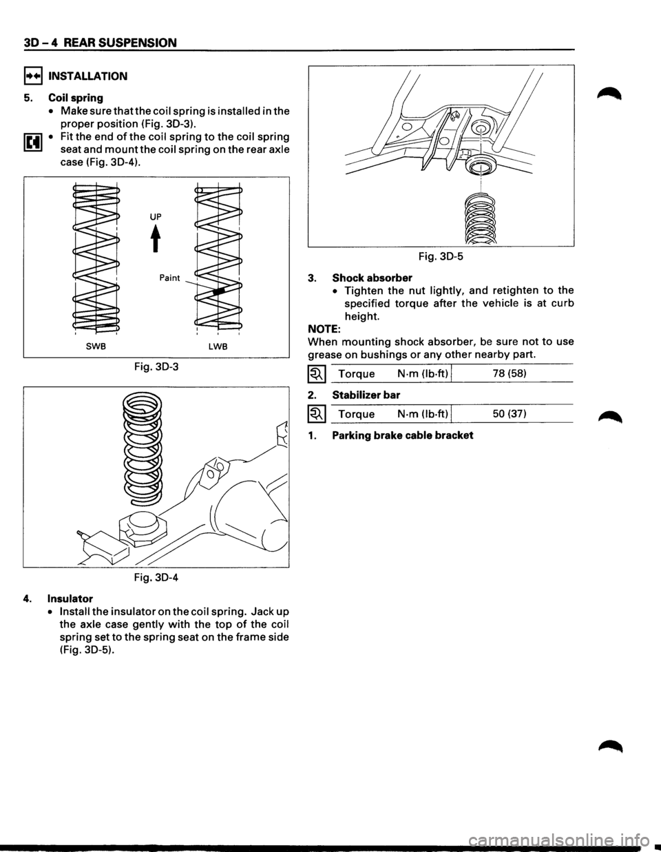
30-4 REAR SUSPENSION
I••IINSTALLATION
5. Coil spring
• Make surethatthecoil spring is installed in the
proper position (Fig. 30-3).
1~41 • Fit the end of the coil spring to the coil spring
seat and
mount the coil spring on the rear axle
case (Fig. 30-4).
UP
t
Paint
SWB LWB
Fig. 30-3
Fig. 30-4
4. Insulator
• Install the insulator on the coil spring. Jack up
the axle case gently with the top of the coil
spring set to the spring seat on the frame side
(Fig.
30-5).
Fig. 30-5
3. Shock absorber
• Tighten the nut lightly, and retighten to the
specified
torque after the vehicle is at curb
height.
NOTE:
When mounting shock absorber, be sure not to use
grease on
bushings or any other nearby part.
~~~ Torque N·m (lb.ft) I 78 (58)
2. Stabilizer bar
~~~ Torque N·m (lb·ft) I 50 (37)
1. Parking brake cable bracket
•