fuse ISUZU TROOPER 1995 Workshop Manual
[x] Cancel search | Manufacturer: ISUZU, Model Year: 1995, Model line: TROOPER, Model: ISUZU TROOPER 1995Pages: 1928
Page 38 of 1928
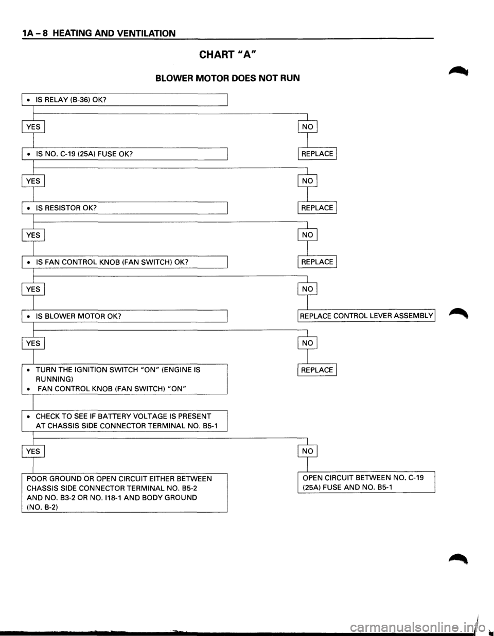
1A-8 HEATING AND VENTILATION
CHART II A"
BLOWER MOTOR DOES NOT RUN
• TURN THE IGNITION SWITCH "ON" (ENGINE IS
RUNNING)
•
FAN CONTROL KNOB (FAN SWITCH) "ON"
• CHECK TO SEE IF BATTERY VOLTAGE IS PRESENT
AT CHASSIS SIDE CONNECTOR TERMINAL NO. B5-1
POOR GROUND OR OPEN CIRCUIT EITHER BETWEEN
CHASSIS SIDE CONNECTOR TERMINAL NO. B5-2
AND NO. B3-2 OR NO. 118-1 AND BODY GROUND
(NO. B-2) (25A)
FUSE AND NO. B5-1
Page 69 of 1928
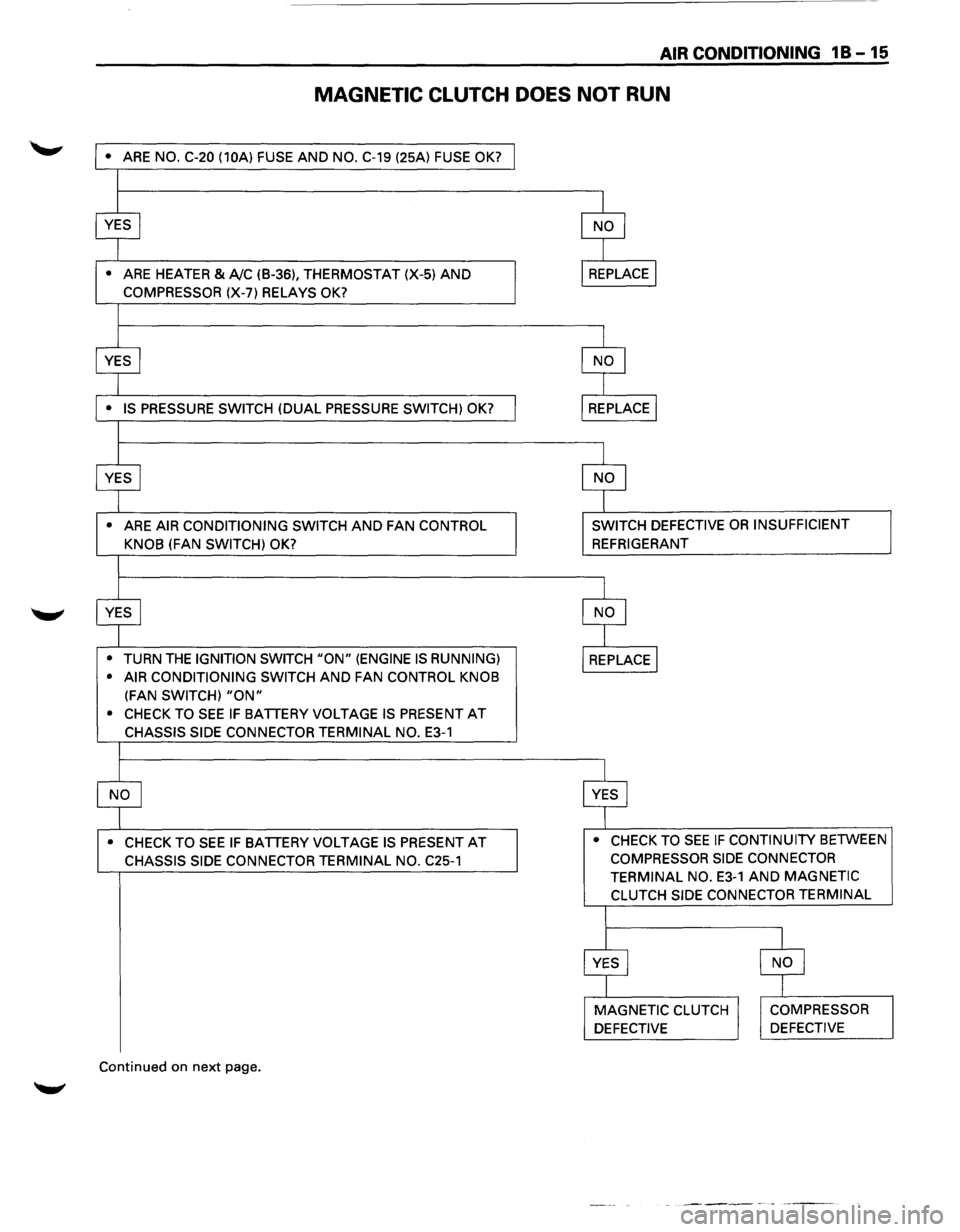
AIR CONDITIONING 1 B -15
MAGNETIC CLUTCH DOES NOT RUN
• ARE NO. C-20 (10A) FUSE AND NO. C-19 (25A) FUSE OK?
•
ARE HEATER & A!C (B-36), THERMOSTAT (X-5) AND
COMPRESSOR (X-7) RELAYS OK?
•
ARE AIR CONDITIONING SWITCH AND FAN CONTROL
KNOB
(FAN SWITCH) OK?
•
TURN THE IGNITION SWITCH "ON" (ENGINE IS RUNNING)
• AIR CONDITIONING SWITCH
AND FAN CONTROL KNOB
(FAN SWITCH) "ON"
• CHECK TO SEE IF BATTERY VOLTAGE IS PRESENT AT
CHASSIS SIDE CONNECTOR TERMINAL NO. E3-1
• CHECK TO SEE IF BATTERY VOLTAGE IS PRESENT AT
CHASSIS SIDE CONNECTOR TERMINAL NO. C25-1
Continued on next page.
SWITCH DEFECTIVE OR INSUFFICIENT
REFRIGERANT
• CHECK TO
SEE IF CONTINUITY BETWEEN
COMPRESSOR SIDE CONNECTOR
TERMINAL NO.
E3-1 AND MAGNETIC
CLUTCH SIDE CONNECTOR TERMINAL
Page 70 of 1928
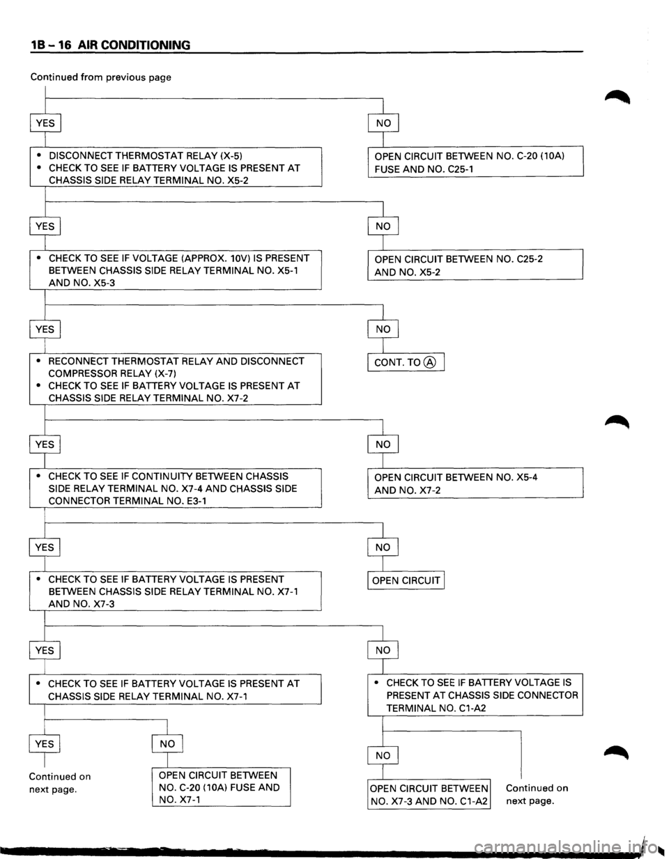
1 B -16 AIR CONDITIONING
Continued from previous page
• DISCONNECT THERMOSTAT RELAY (X-5)
• CHECK TO SEE IF BATTERY VOLTAGE IS PRESENT AT
CHASSIS SIDE RELAY TERMINAL NO. X5-2
• CHECK TO SEE IF VOLTAGE (APPROX. 10V) IS PRESENT
BETWEEN CHASSIS SIDE RELAY TERMINAL NO. X5-1
AND NO. X5-3
• RECONNECT THERMOSTAT RELAY AND DISCONNECT
COMPRESSOR
RELAY (X-7)
• CHECK TO SEE IF BATTERY VOLTAGE IS PRESENT AT
CHASSIS SIDE RELAY TERMINAL NO. X7-2
• CHECK TO SEE IF CONTINUITY BETWEEN CHASSIS
SIDE
RELAY TERMINAL NO. X7-4 AND CHASSIS SIDE
CONNECTOR TERMINAL NO. E3-1
• CHECK TO SEE IF BATTERY VOLTAGE IS PRESENT
BETWEEN CHASSIS SIDE RELAY TERMINAL NO. X7-1
AND NO. X7-3
• CHECK TO SEE IF BATTERY VOLTAGE IS PRESENT AT
CHASSIS SIDE RELAY TERMINAL NO. X7-1
Continued on
next page. OPEN
CIRCUIT BETWEEN
NO. C-20 (10A)
FUSE AND
NO. X7-1 OPEN
CIRCUIT BETWEEN
NO. C-20 (10A)
FUSE AND NO. C25-1
AND NO. X5-2
AND NO. X7-2
• CHECK TO SEE IF BATTERY VOLTAGE IS
PRESENT AT CHASSIS SIDE CONNECTOR
TERMINAL NO. C1-A2
Continued on
NO. X7-3 AND NO. C1-A2 next page.
Page 71 of 1928
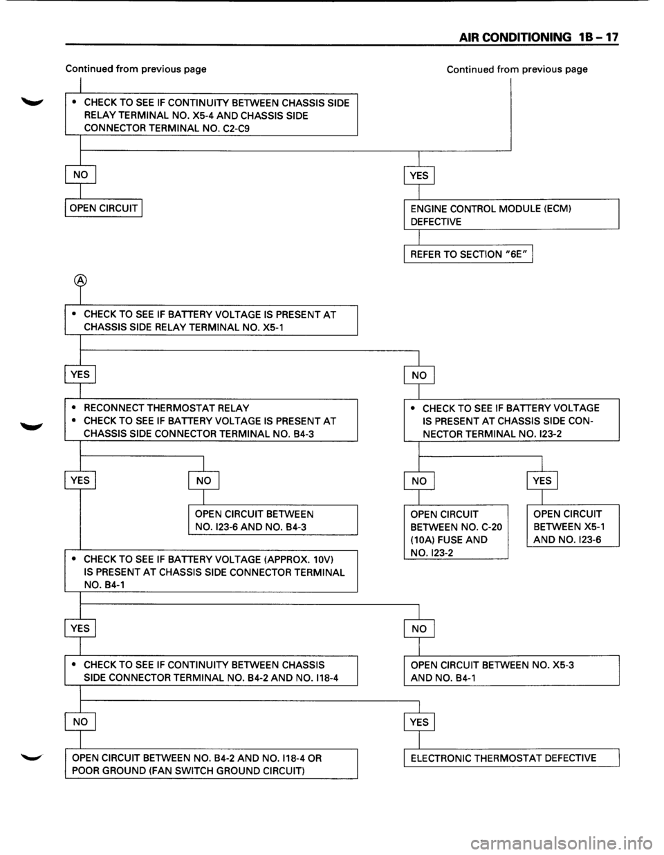
Continued from previous page
~ • CHECK TO SEE IF CONTINUITY BETWEEN CHASSIS SIDE
RELAY TERMINAL NO. X5-4 AND CHASSIS SIDE
CONNECTOR
TERMINAL NO. C2-C9
• CHECK TO SEE IF BATTERY VOLTAGE IS PRESENT AT
CHASSIS SIDE RELAY TERMINAL NO. XS-1
•
RECONNECT THERMOSTAT RELAY
• CHECK TO SEE IF BATTERY VOLTAGE IS PRESENT AT
CHASSIS SIDE CONNECTOR TERMINAL NO. B4-3
OPEN CIRCUIT BETWEEN
NO. 123-6 AND NO. B4-3
• CHECK TO SEE IF BATTERY VOLTAGE (APPROX. 10V)
IS PRESENT
AT CHASSIS SIDE CONNECTOR TERMINAL
NO. B4-1
• CHECK TO SEE IF CONTINUITY BETWEEN CHASSIS
SIDE CONNECTOR
TERMINAL NO. B4-2 AND NO. 118-4
OPEN CIRCUIT BETWEEN NO. B4-2 AND NO. 118-4 OR
POOR GROUND (FAN SWITCH GROUND CIRCUIT)
AIR CONDITIONING 18-17
Continued from previous page
• CHECK TO SEE IF BATTERY VOLTAGE
IS PRESENT
AT CHASSIS SIDE CON
NECTOR TERMINAL NO.
123-2
OPEN CIRCUIT
BETWEEN NO. C-20
(10A) FUSE
AND
NO. 123-2
AND NO. B4-1
OPEN CIRCUIT
BETWEEN XS-1
AND NO. 123-6
ELECTRONIC THERMOSTAT DEFECTIVE
Page 245 of 1928
REAR AXLE 48-3
DIAGNOSIS OF REAR AXLE NOISE
Many noises that seem to come from the rear axle
actually
originate from other sources such as tires,
road surface, wheel bearings, engine, transmission,
muffler,
or body drumming. Investigate to find the
source
ofthe noise before disassembling the rear axle.
Rear axles,
like any other mechanical device, are not
absolutely quiet but should be considered quiet unless
some abnormal noise is present.
To make a systematic check
for axle noise, observe the
following:
1. Select a level asphalt road to reduce tire noise and
body drumming.
2. Check rear axle lubricant level to assure correct
level, and then drive the vehicle far enough to
thoroughly warm up the rear axle lubricant.
3. Note the speed at which noise occurs. Stop the
vehicle and put the transmission in neutral. Run
the engine speed
slowly up and down to
determine if the noise is caused by exhaust,
muffler noise, or other engine conditions.
4. Tire noise changes with different road surfaces;
axle noises do not. Temporarily inflate all tires to
344
kPa (50 psi) (for test purposes only). This will
change noise caused by tires but will not affect
noise caused by the rear
axle.
Rear axle nose usually stops when coasting at
speeds under
48 km/h (30 mph); however, tire
noise continues
with a lower tone. Rear axle noise
usually changes when comparing pull and coast,
but tire noise stays about the same.
Distinguish between tire noise and rear
axle noise
by noting
if the noise changes with various
speeds
or sudden acceleration and deceleration.
Exhaust and
axle noise vary under these
conditions,
while tire noise remains constant and
is more pronounced at speeds
of 32 to 48 km/h
(20 to 30 mph). Further check for tire noise by
driving the vehicle
over smooth pavements or dirt
roads (not gravel) with the tires at normal
pressure.
If the noise is caused by tires, it will
change noticeably with changes in road surface.
5. Loose or rough front wheel bearings will cause
noise
which may be confused with rear axle
noise; however, front wheel bearing noise does
not change when comparing drive and coast.
Light application
of the brake while holding
vehicle speed steady
will often cause wheel
bearing noise to diminish. Front wheel bearings
may be checked for noise by jacking up the
wheels and spinning them
or by shaking the
wheels
to determine if bearings are loose.
6. Rear suspension rubber bushings and spring
insulators dampen
out rear axle noise when
correctly installed. Check to see that there is no
link or rod loosened or metal-to-metal contact.
7. Make sure that there is no metal-to-metal contact
between the
floor and the frame.
After the noise has been determined to be in the axle,
the type of axle noise should be determined, in order to
make any necessary repairs.
GEAR NOISE
Gear noise (whine) is audible from 32 to 89 km/h (20 to
55 mph) under four driving conditions.
1. In drive under acceleration or heavy pull.
2. Driving under load or under constant speed.
3. When using enough throttle to keep the vehicle
from driving the engine while the vehicle slows
down gradually (engine still pulls slightly).
4. When coasting with the vehicle in gear and the
throttle closed. The gear noise is
usually more
noticeable between 48 and 64
km/h (30 and 40
mph) and 80 and 89 km/h (50 and 55 mph).
BEARING NOISE
Bad bearings generally produce a rough growl or
grating sound, rather than the whine typical of gear
noise. Bearing noise frequently
"wow-wows" at
bearing rpm, indicating a bad pinion
or rear axle side
bearing. This noise can
be confused with rear wheel
bearing noise.
REAR WHEEL BEARING NOISE
Rear wheel bearing noise continues to be heard while
coasting at low speed with transmission in the neutral.
Noise may diminish by gentle braking. Jack up the rear
wheels, spin them by hand and
listen for noise at the
hubs. Replace any faulty
wheel bearings.
KNOCK AT LOW SPEEDS
Low speed knock can be caused by worn universal
joints or a side gear hub counter bore in the cage that is
worn oversize. Inspect and replace universal joints or
cage and side gears as required.
BACKLASH CLUNK
Excessive clunk on acceleration and deceleration can
be caused by a worn rear axle pinion shaft, a worn
cage, excessive clearance between the axle and the
side gear splines, excessive clearance between the
side gear hub and the counterbore in the cage,
worn
pinion and side gear teeth, worn thrust washers, or
excessive drive pinion and ring gear backlash.
Remove
worn parts and replace as required. Select
close-fitting parts when possible. Adjust pinion and
ring gear backlash.
Page 325 of 1928
HYDRAULIC BRAKES 5A-5
ON-VEHICLE SERVICE
FILLING MASTER CYLINDER
RESERVOIR
'\fl CAUTION:
'VI • Use only specified brake fluid. Do not use any
fluid which contains a petroleum base. Do not
use a container which has been used for
petroleum based fluids or a container which is
wet with water. Petroleum based fluids will
cause swelling and distortion of rubber parts in
the
hydraulic brake system. Water mixed with
brake fluid lowers the fluid boiling point. Keep
all fluid containers capped to prevent contami
nation.
• Always fill the master cylinder reservoir when
the engine is
cold.
•
Never allow the brake fluid to come in contact
with the painted surfaces.
The master
cylinder reservoir must be kept properly
filled
to ensure adequate reserve and to prevent air
and moisture
from entering the hydraulic system.
However, because
of expansion due to heat absorbed
from the brakes and the engine, the reservoir must not
be overfilled. The brake fluid reservoir is on the master
cylinder, which is located under the hood on the
left
side of the cowl. Thoroughly clean reservoir cap
before
removal to avoid getting dirt into reservoir.
Remove cap and diaphragm.
Add fluid as required to
bring level to the "MAX" mark on the reservoir tank.
Use
"DOT 3" Hydraulic Brake Fluid. If the fluid cap
diaphragm is stretched, return
it to the original position
before
installing.
DETERIORATION OF BRAKE FLUID
Using any other brake fluid than specified or brake fluid
with mineral oil or water mixed in will drop the boiling
point of brake fluid. It may, in turn, result in vapor lock
or deteriorated rubber parts of the hydraulic system.
Be sure to change brake fluid at specified intervals.
If rubber parts are deteriorated, remove all the system
parts and
clean them with alcohol. Prior to reassembly,
dry the cleaned parts with air to remove the alcohol.
Replace all
hoses and rubber parts of the system.
LEAKAGE OF BRAKE FLUID
With engine idling, set shift lever in the neutral position
and continue to depress brake
pedal at a constant
pressure.
Should the pedal stroke become deeper gradually,
leak from the hydraulic pressure system is possible.
Make sure
by visual check that there is no leak.
BLEEDING BRAKE HYDRAULIC SYSTEM
A bleeding operation is necessary to remove air from
the hydraulic brake system whenever air is introduced
into the hydraulic system.
It may be necessary to bleed
the hydraulic system at all four brakes if air has been
introduced through a
low fluid level or by dis
connecting brake pipes at the master cylinder. If a
brake pipe is disconnected at one
wheel, only that
wheel cylinder/caliper needs to be bled. If pipes are
disconnected at any fitting
located between master
cylinder and brakes, then the brake system served by
the disconnected pipe must
be bled.
1. For 4-wheel Antilock Brake System (ABS)
equipped
vehicle, be sure to remove the ABS
main fuse
40A located at the relay and fuse box
before
bleeding air. If you attempt to bleed air
without removing the main fuse, air cannot be let
out thoroughly, and this may cause damage to the
hydraulic unit.
After bleeding air, be sure to
replace the ABS main fuse back to its original
position.
2. Set the parking brake completely, then start the
engine.
NOTE:
The vacuum booster will be damaged if the
bleeding operation is performed with the engine
off.
3. Remove the master cylinder reservoir cap.
4. Fill the master cylinder reservoir with brake fluid.
Keep the reservoir at least half full during the air
bleeding operation.
5. Always use new brake fluid for replenishment.
6. In replenishing brake fluid, take care that air
bubbles do not enter the brake fluid.
•
When the master cylinder is replaced or
overhauled, first bleed the air from the master
cylinder, then from each
wheel cylinder and
caliper following the procedures described
below.
Bleeding the master cylinder (Fig. 5A-1}
7. Disconnect the rear wheel brake pipe
cylinder (Fig. 5A-1 ). Check the fluid level
and replenish as necessary. If replenished, leave
the system for at least one minute.
8. Depress the brake pedal slowly once and hold it
depressed.
9. Completely seal the delivery port of the master
cylinder where the pipe was disconnected with
your finger, then release the brake pedal slowly.
10. Release your finger from the delivery port when
the brake
pedal returns completely.
11. Repeat steps 7 through 9 until the brake fluid
comes out of the delivery port during step 7.
Page 331 of 1928
INSPECTION OF BRAKE PAD LINING
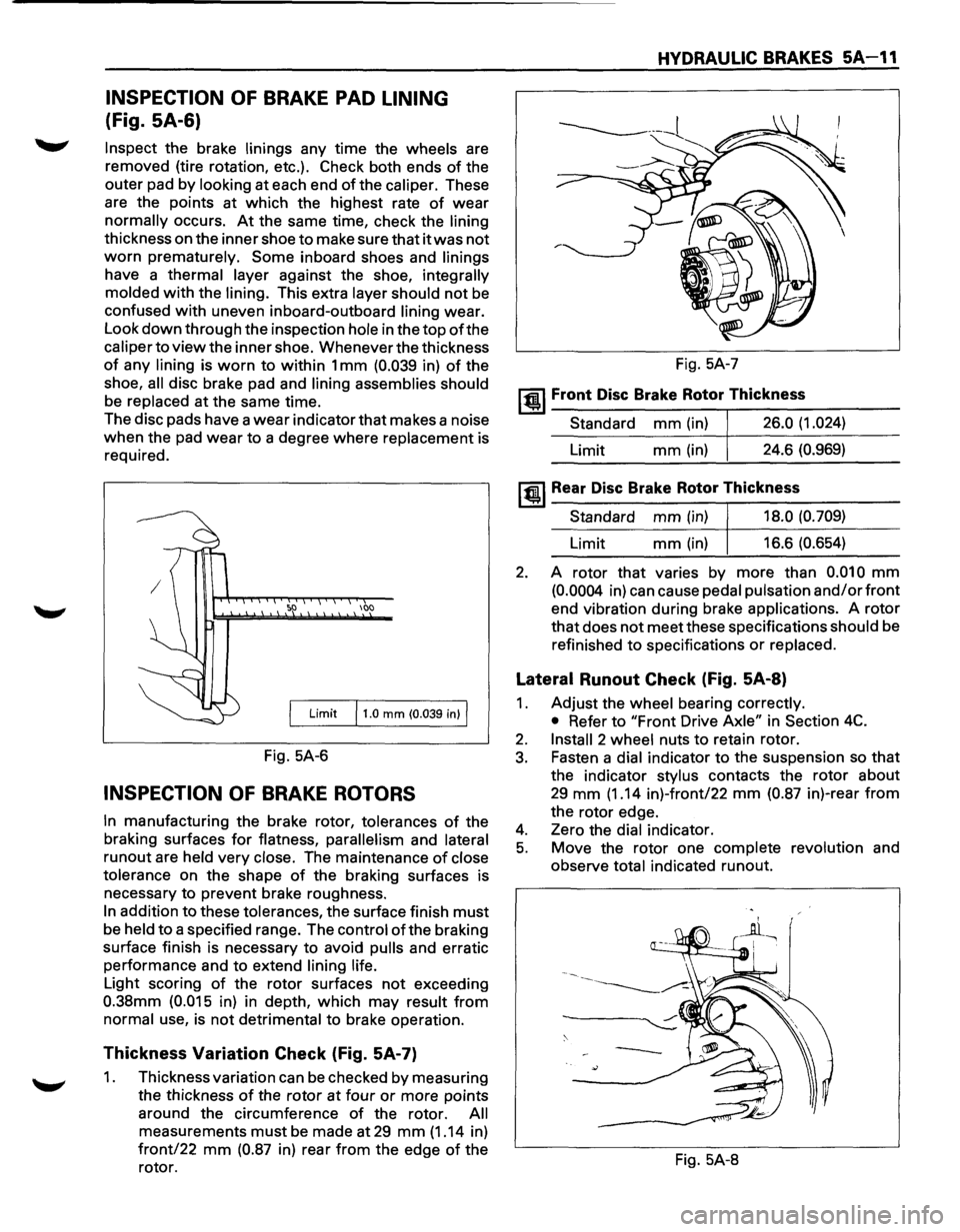
(Fig. SA-6)
Inspect the brake linings any time the wheels are
removed (tire rotation, etc.). Check both ends
of the
outer pad by
looking at each end of the caliper. These
are the points at which the highest rate
of wear
normally occurs. At the same time, check the lining
thickness on the inner shoe to make sure that it was not
worn prematurely. Some inboard shoes and linings
have a thermal layer against the shoe, integrally
molded
with the lining. This extra layer should not be
confused with uneven inboard-outboard lining wear.
Look
down through the inspection hole in the top of the
caliper to view the inner shoe. Whenever the thickness
of any lining is worn to within 1 mm (0.039 in) of the
shoe,
all disc brake pad and lining assemblies should
be replaced at the same time.
The disc pads have a
wear indicator that makes a noise
when the pad wear to a degree where replacement is
required.
100
Limit 11.0 mm (0.039 in) I
Fig. 5A-6
INSPECTION OF BRAKE ROTORS
In manufacturing the brake rotor, tolerances of the
braking surfaces
for flatness, parallelism and lateral
runout are held very close. The maintenance of close
tolerance
on the shape of the braking surfaces is
necessary to prevent brake roughness.
In addition to these tolerances, the surface finish must
be held to a specified range. The control ofthe braking
surface finish is necessary to avoid
pulls and erratic
performance and to extend
lining life.
Light scoring of the rotor surfaces not exceeding
0.38mm (0.015 in) in depth, which may result from
normal use, is not detrimental to brake operation.
Thickness Variation Check (Fig. 5A-7)
1. Thickness variation can be checked by measuring
the thickness
of the rotor at four or more points
around the circumference
of the rotor. All
measurements must be made at 29 mm (1.14 in)
front/22 mm (0.87 in) rear from the edge of the
rotor.
HYDRAULIC BRAKES 5A-11
Fig. 5A-7
~~~ Front Disc Brake Rotor Thickness
Standard mm (in) 26.0 (1.024)
Limit mm(in) 24.6 (0.969)
~~~Rear Disc Brake Rotor Thickness
Standard mm (in) 18.0 (0.709)
Limit mm (in) 16.6 (0.654)
2. A rotor that varies by more than 0.010 mm
(0.0004 in) can cause pedal pulsation and/or front
end vibration during brake applications. A rotor
that does not meet these specifications should be
refinished
to specifications or replaced.
Lateral Runout Check (Fig. 5A-8)
1. Adjust the wheel bearing correctly.
• Refer to "Front Drive Axle" in Section 4C.
2. Install 2 wheel nuts to retain rotor.
3. Fasten a dial indicator to the suspension so that
the indicator stylus contacts the rotor about
29 mm (1.14 in)-front/22 mm (0.87 in)-rear from
the rotor edge.
4. Zero the dial indicator.
5. Move the rotor one complete revolution and
observe
total indicated runout.
Fig. 5A-8
Page 374 of 1928
5A3-6 REAR WHEEL ANTILOCK BRAKE SYSTEM
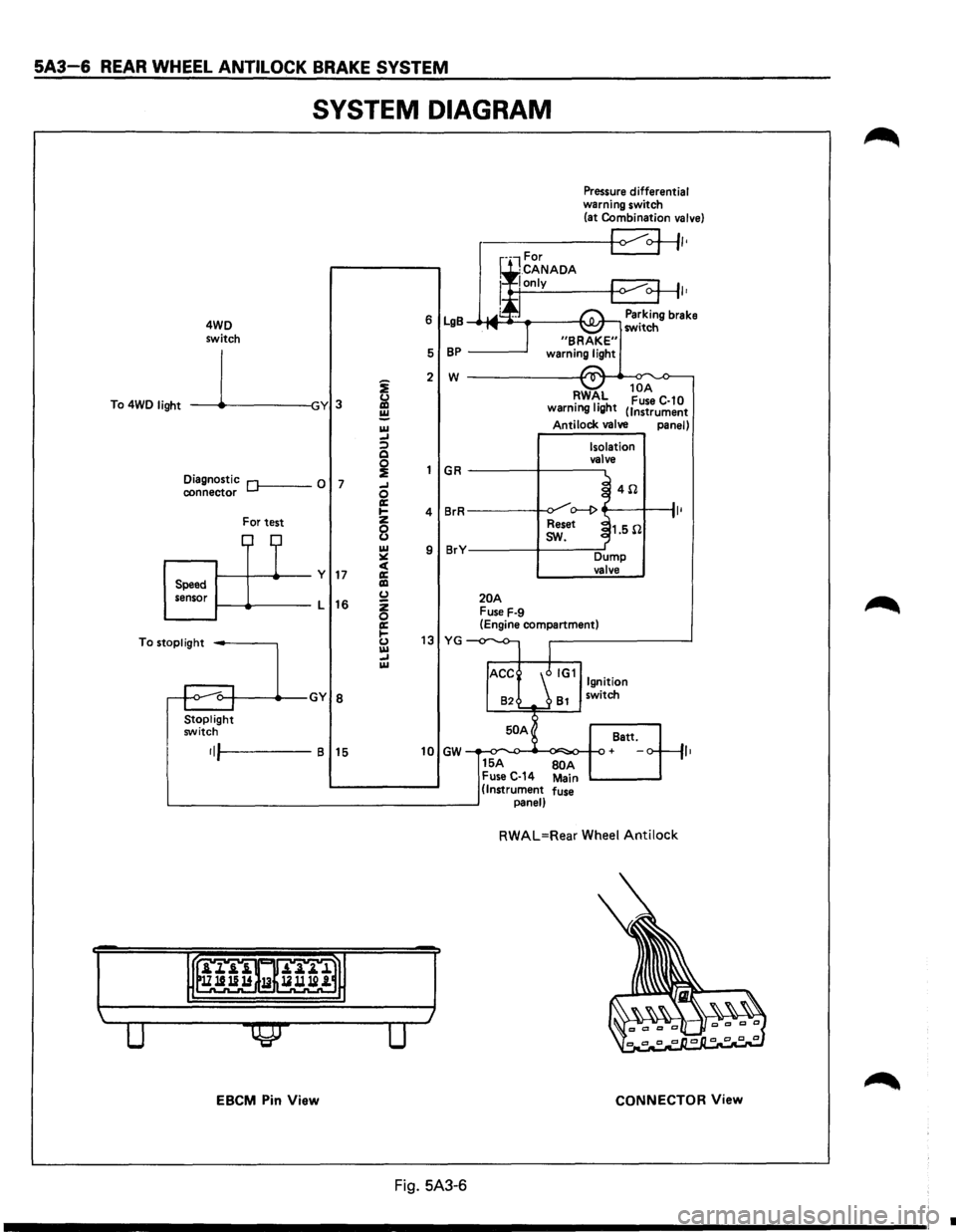
SYSTEM DIAGRAM
4WD
switch
To 4WD
light -----11~-----lGY 3
Diagnostic Of------0 7 connector
For test
1-----11---+--y 17 Speed
sensor 1-----lt-----L
16
To
stoplight -----,
Stoplight switch
•IJI-----B 15
EBCM Pin View
i
&l ~ IU _, :;) Q
~ _, 0 a: .... z
8 IU ~ c( a: liD (.) z 0 a: 1-(.) IU _, IU
Pressure differential warning switch
(at Combination valve)
r-----+-<1 ~+II•
I•
6 LgB Parking brake _.-MI ____ ___,I'\.JI.Jr-, switch
5
BP -----'
2 w ------------~~._~
GR
4 BrR
9 BrY
20A Fuse F-9
RWAL 10
A •
1• h Fuse C-10
warnmg IQ t (Instrument
Antilock valve panel)
Isolation
valve
~ 4il .J o--1> ~
Reset ~1.5il
I
sw.
Dump valve
(Engine compartment)
13 YG -
82 81 switch
50 A
Batt.
10 GW + ,,
15A BOA Fuse C-14 Main (Instrument fuse panel)
RWAL=Rear Wheel Antilock
CONNECTOR View
Fig. 5A3-6
•
Page 375 of 1928
REAR WHEEL ANTILOCK BRAKE SYSTEM 5A3-7
REAR WHEEL ANTILOCK (RWAL) SYSTEM DIAGNOSTICS
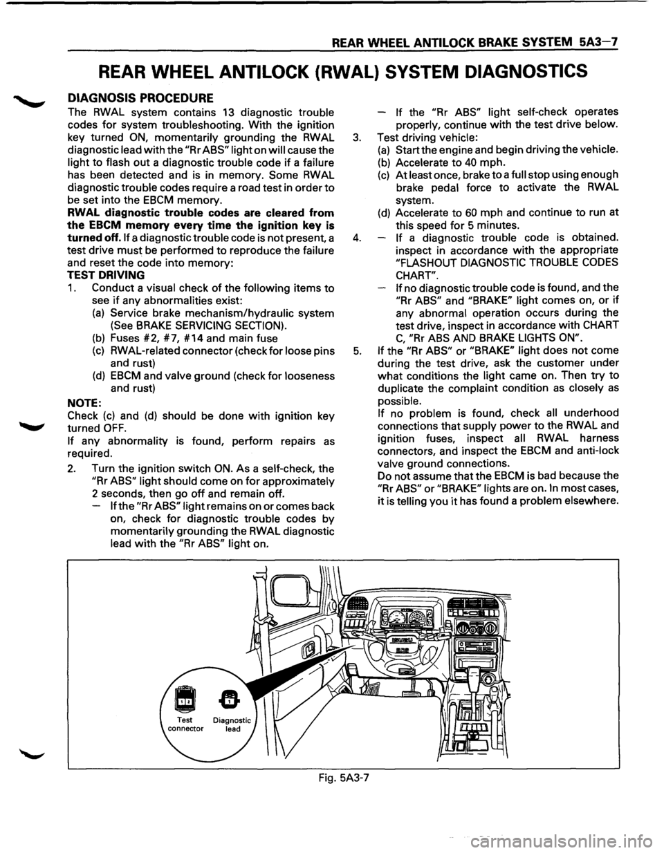
DIAGNOSIS PROCEDURE
The RWAL system contains 13 diagnostic trouble
codes
for system troubleshooting. With the ignition
key turned
ON, momentarily grounding the RWAL
diagnostic lead
with the "Rr ABS" light on will cause the
light
to flash out a diagnostic trouble code if a failure
has been detected and is in memory.
Some RWAL
diagnostic trouble codes require a road test in order
to
be set into the EBCM memory.
RWAL diagnostic trouble codes are cleared from
the
EBCM memory every time the ignition key is
turned off. If a diagnostic trouble code is not present, a
test drive
must be performed to reproduce the failure
and reset the code into
memory:
TEST DRIVING
1. Conduct a visual check of the following items to
see if any abnormalities exist:
(a) Service brake mechanism/hydraulic system
(See BRAKE SERVICING SECTION).
(b) Fuses #2, #7, #14 and main fuse
(c) RWAL-related connector (check for loose pins
and rust)
(d) EBCM and valve ground (check for looseness
and rust)
NOTE:
Check
(c) and (d) should be done with ignition key
turned
OFF.
If any abnormality is found, perform repairs as
required.
2. Turn the ignition switch ON. As a self-check, the
"Rr ABS" light should come on for approximately
2 seconds, then go
off and remain off.
If the "Rr ABS" light remains on or comes back
on, check
for diagnostic trouble codes by
momentarily grounding the RWAL diagnostic
lead
with the "Rr ABS" light on. -
If the "Rr
ABS" light self-check operates
properly, continue
with the test drive below.
3. Test driving vehicle:
(a) Start the engine and begin driving the vehicle.
(b) Accelerate to 40 mph.
(c) At least once, brake to a full stop using enough
brake pedal force
to activate the RWAL
system.
(d) Accelerate to 60 mph and continue to run at
this speed
for 5 minutes.
4. If a diagnostic trouble code is obtained.
inspect in accordance
with the appropriate
"FLASHOUT DIAGNOSTIC TROUBLE CODES
CHART".
If
no diagnostic trouble code is found, and the
"Rr ABS" and "BRAKE" light comes on, or if
any abnormal operation occurs during the
test drive, inspect in accordance
with CHART
C, "Rr ABS AND BRAKE LIGHTS ON".
5. If the "Rr ABS" or "BRAKE" light does not come
during the test drive, ask the customer under
what conditions the light came on. Then try to
duplicate the complaint condition
as closely as
possible.
If no problem is found, check all underhood
connections that supply power
to the RWAL and
ignition fuses, inspect
all RWAL harness
connectors, and inspect the
EBCM and anti-lock
valve ground connections.
Do not assume that the
EBCM is bad because the
"Rr ABS" or "BRAKE" lights are on. In most cases,
it is telling you it has found a problem elsewhere.
Fig. 5A3-7
Page 377 of 1928
REAR WHEEL ANTILOCK BRAKE SYSTEM 5A3-9
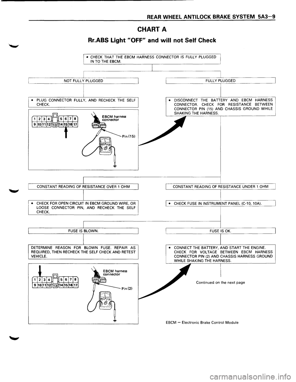
CHART A
Rr.ABS Light "OFF" and will not Self Check
• CHECK THAT THE EBCM HARNESS CONNECTOR IS FULLY PLUGGED IN TO THE EBCM.
• PLUG CONNECTOR FULLY, AND RECHECK THE SELF
CHECK.
• CHECK FOR OPEN CIRCUIT IN EBCM GROUND WIRE, OR LOOSE CONNECTOR PIN, AND RECHECK THE SELF
CHECK.
DETERMINE REASON FOR BLOWN FUSE. REPAIR AS
REQUIRED, THEN RECHECK THE SELF CHECK AND RETEST VEHICLE. •
DISCONNECT
THE BATTERY AND EBCM HARNESS
CONNECTOR. CHECK FOR RESISTANCE BETWEEN
CONNECTOR PIN (15) AND CHASSIS GROUND WHILE
SHAKING THE HARNESS.
• CONNECT THE BATTERY, AND START THE ENGINE. CHECK FOR VOLTAGE BETWEEN EBCM HARNESS
CONNECTOR PIN (2) AND CHASSIS HARNESS GROUND WHILE SHAKING THE HARNESS.
Continued on the next page
EBCM
~ Electronic Brake Control Module