coolant level ISUZU TROOPER 1995 User Guide
[x] Cancel search | Manufacturer: ISUZU, Model Year: 1995, Model line: TROOPER, Model: ISUZU TROOPER 1995Pages: 1928
Page 637 of 1928
E!) INSTALLATION
6. Radiator assembly
• Install cushion rubbers on both sides of radia
tor bottom.
• Install radiator assembly with hose, taking
care
not to damage the radiator core with a fan
blade.
5. Bracket
• Support the radiator uppertankwith the bracket
and secure the radiator.
4. Reserve tank hose
3. Fan guide, lower
2. Radiator hose
• Connect inlet hose and outlet hose to the
engine.
1. Oil cooler hose (A/T)
• Connect oil cooler hose for automatic trans-
mission.
• Connect battery ground cable.
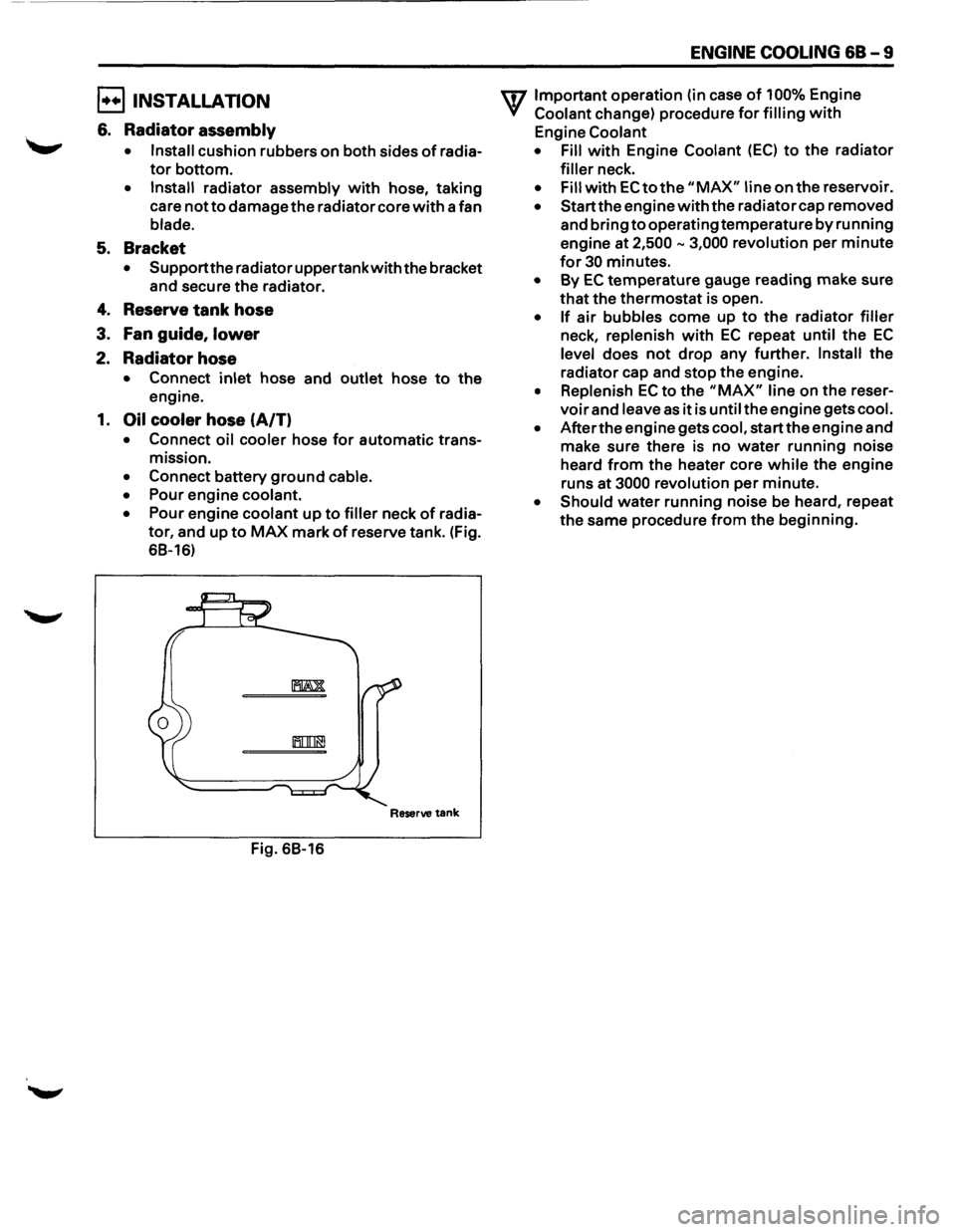
• Pour engine coolant.
• Pour engine coolant up to filler neck of radia
tor, and up to MAX mark of reserve tank. (Fig.
68-16)
Reserve tank
Fig. 68-16
ENGINE COOLING 68-9
U7 Important operation (in case of 100% Engine
V Coolant change) procedure for filling with
Engine Coolant
• Fill
with Engine Coolant (EC) to the radiator
filler neck.
• Fill with EC to the "MAX" line on the reservoir.
• Start the engine with the radiator cap removed
and bring
to operating temperature by running
engine at
2,500-3,000 revolution per minute
for 30 minutes.
• By EC temperature gauge reading make sure
that the thermostat is open.
• If air bubbles come up to the radiator filler
neck, replenish with EC repeat until the EC
level does not drop any further. Install the
radiator cap and stop the engine.
• Replenish EC to the "MAX" line on the reser
voir and leave as it is until the engine gets cool.
• After the engine gets cool, start the engine and
make sure there is no
water running noise
heard
from the heater core while the engine
runs
at 3000 revolution per minute.
• Should water running noise be heard, repeat
the same procedure from the beginning.
Page 703 of 1928
DRIVEABILITY AND EMISSIONS 6E2-7
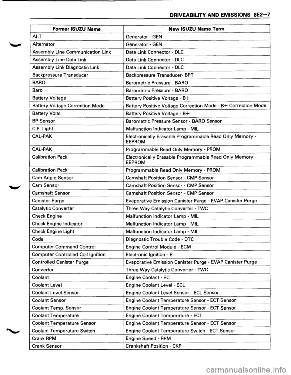
Former ISUZU Name New ISUZU Name Term
ALT Generator -GEN
Alternator
Generator -GEN
Assembly Line Communication Link
Data Link Connector -DLC
Assembly Line Data Link
Data Link Connector -DLC
Assembly Link Diagnostic Link
Data Link Connector -DLC
Backpressure Transducer
Backpressure Transducer-BPT
BARO Barometric Pressure -BARO
Baro
Barometric Pressure -BARO
Battery Voltage
Battery Positive Voltage-B+
Battery Voltage Correction Mode Battery Positive Voltage Correction Mode -B+ Correction Mode
Battery Volts
Battery
Positive Voltage-B+
BP Sensor Barometric Pressure Sensor -BARO Sensor
C.E. Light
Malfunction Indicator Lamp -MIL
CAL-PAK Electronically
Erasable Programmable Read Only Memory -
EEPROM
CAL-PAK
Programmable Read Only Memory -PROM
Calibration Pack Electronically Erasable Programmable Read Only Memory -
EEPROM
Calibration Pack
Programmable Read Only Memory-PROM
Cam Angle Sensor Camshaft Position Sensor -CMP Sensor
Cam Sensor Camshaft Position Sensor -CMP Sensor
Camshaft Sensor Camshaft Position Sensor -CMP Sensor
Canister Purge Evaporative Emission Canister Purge-EVAP Canister Purge
Catalytic Converter
Three Way Catalytic Converter-TWC
Check Engine
Malfunction
Indicator Lamp -MIL
Check Engine Indicator Malfunction Indicator Lamp -MIL
Check Engine Light
Malfunction Indicator Lamp-MIL
Code Diagnostic Trouble Code -DTC
Computer Command Control Engine Control Module -ECM
Computer Controlled Coil Ignition Electronic Ignition -El
Controlled Canister Purge Evaporative Emission Canister Purge-EVAP Canister Purge
Converter Three Way Catalytic Converter -TWC
Coolant Engine Coolant -EC
Coolant Level
Engine Coolant Level -ECL
Coolant Level Sensor Engine Coolant Level Sensor -ECL Sensor
Coolant Sensor Engine Coolant Temperature Sensor -ECT Sensor
Coolant Temp. Sensor Engine Coolant Temperature Sensor-ECT Sensor
Coolant Temperature Engine Coolant Temperature -ECT
Coolant Temperature Sensor Engine Coolant Temperature Sensor-ECT Sensor
Coolant Temperature Switch Engine Coolant Temperature Switch -ECT Sensor
Crank RPM Engine Speed -RPM
Crank Sensor Crankshaft Position-CKP
Page 707 of 1928
DRIVEABILITY AND EMISSIONS 6E2-11
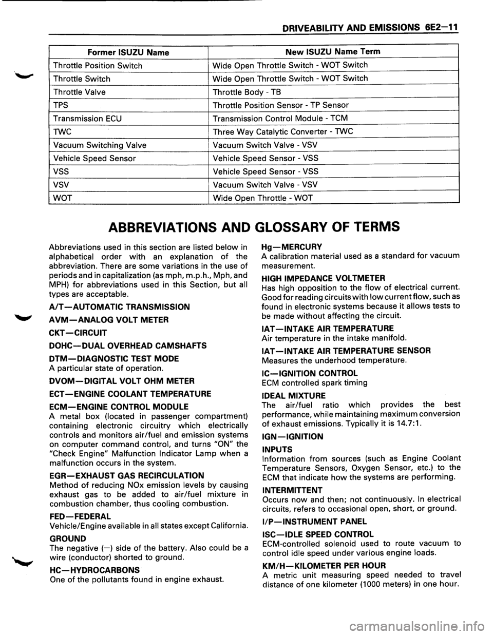
Former ISUZU Name New ISUZU Name Term
Throttle Position Switch Wide Open Throttle Switch -WOT Switch
Throttle Switch
Wide Open Throttle Switch -WOT Switch
Throttle Valve Throttle
Body -TB
TPS Throttle Position Sensor -TP Sensor
Transmission ECU Transmission Control Module -TCM
TWC Three
Way
Catalytic Converter -TWC
Vacuum Switching Valve Vacuum Switch Valve -VSV
Vehicle Speed Sensor Vehicle
Speed Sensor
-VSS
vss Vehicle Speed Sensor -VSS
vsv Vacuum Switch Valve -VSV
WOT
Wide Open Throttle -WOT
ABBREVIATIONS AND GLOSSARY OF TERMS
Abbreviations used in this section are listed below in
alphabetical order with an explanation of the
abbreviation. There are some variations in the use
of
periods and in capitalization (as mph, m.p.h., Mph, and
MPH) for abbreviations used in this Section, but all
types are acceptable.
A/T -AUTOMATIC TRANSMISSION
AVM-ANALOG VOLT METER
CKT -CIRCUIT
DOHC-DUAL OVERHEAD CAMSHAFTS
DTM-DIAGNOSTIC TEST MODE
A particular state of operation.
DVOM-DIGITAL VOLT OHM METER
ECT -ENGINE COOLANT TEMPERATURE
ECM-ENGINE CONTROL MODULE
A metal box (located in passenger compartment)
containing
electronic circuitry which electrically
controls
and monitors air/fuel and emission systems
on
computer command control, and turns "ON" the
"Check Engine"
Malfunction Indicator Lamp when a
malfunction occurs in the system.
EGR-EXHAUST GAS RECIRCULATION
Method of reducing NOx emission levels by causing
exhaust gas
to be added to air/fuel mixture in
combustion chamber, thus
cooling combustion.
FED-FEDERAL
Vehicle/Engine available in all states except California.
GROUND
The negative (-) side of the battery. Also could be a
wire (conductor) shorted to ground.
HC-HVDROCARBONS
One of the pollutants found in engine exhaust.
Hg-MERCURV
A calibration material used as a standard for vacuum
measurement.
HIGH IMPEDANCE VOLTMETER
Has high opposition to the flow of electrical current.
Good
for reading circuits with low currentflow, such as
found in electronic systems because it allows tests to
be made without affecting the circuit.
IAT -INTAKE AIR TEMPERATURE
Air temperature in the intake manifold.
IAT-INTAKE AIR TEMPERATURE SENSOR
Measures the underhood temperature.
IC-IGNITION CONTROL
ECM controlled spark timing
IDEAL MIXTURE
The air/fuel ratio which provides the best
performance,
while maintaining maximum conversion
of exhaust emissions. Typically it is 14.7:1.
IGN-IGNITION
INPUTS
Information from sources (such as Engine Coolant
Temperature Sensors, Oxygen Sensor, etc.) to the
ECM that indicate how the systems are performing.
INTERMITTENT
Occurs now and then; not continuously. In electrical
circuits, refers to occasional open, short, or ground.
liP-INSTRUMENT PANEL
ISC-IDLE SPEED CONTROL
ECM-controlled solenoid used to route vacuum to
control idle speed under various engine loads.
KM/H-KILOMETER PER HOUR
A metric unit measuring speed needed to travel
distance of one kilometer (1 000 meters) in one hour.
Page 791 of 1928
IGNITION SYSTEM
• CHECK: Ignition timing, using a "Scan tool".
• CHECK: Ignition system; wires, plugs, electronic
ignition, etc.
ENGINE MECHANICAL
• CHECK: Perform a cylinder compression check.
See ENGINE MECHANICAL DIAGNOSIS
(SECTION 6).
• CHECK: For correct camshaft or weak valve
springs.
ADDITIONAL CHECKS
• CHECK: Manifold absolute pressure sensor.
Refer to
CHART C-10.
• CHECK: Throttle linkage for sticking or binding.
• CHECK: Park/neutral position switch circuit. See
CHART C-1A,
or use "Scan tool" and be
sure
tool indicates vehicle is in drive with
gear selector in drive or overdrive.
DRIVEABILITY AND EMISSIONS 6E2-95
• CHECK:
• CHECK:
• CHECK:
• CHECK:
• CHECK:
• CHECK:
Idle air control operation, use CHART C-
2C.
Exhaust gas recirculation valve. There
should be no exhaust gas recirculation at
idle. Refer to CHART C-7A.
Air conditioning (A/C) signal to engine
control module, "Scan tool" should
indicate A/C is being requested when
ever
A/C is selected. If problem exists
with A/C "ON," check A/C system
operation
CHART C-10.
Positive crankcase ventilation valve for
proper operation. Refer to "Positive
Crankcase Ventilation (PCV),"
Section
"6E2-C13."
For broken motor mounts.
Generator output
voltage. Repair if less
than 9 or more than 16 volts.
POOR FUEL ECONOMY
Definition: Fuel economy, as measured by an actual
road test, is noticeably lower than
expected.
Also, fuel economy is
noticeably lower than it was on this car at
one time,
as previously shown by an actual
road test.
PRELIMINARY CHECKS
• Perform the careful visual checks as described at
start
of "Symptoms," Section "6E2-B."
• Visually (physically)
check: Vacuum hoses for
splits, kinks, and proper connections as shown on
"Vehicle Emission Control Information" label.
• Check
owner's driving habits.
Is A/C "ON" full time (Defroster mode "ON")?
Are tires at correct pressure?
Are
excessively heavy loads being carried?
Is acceleration too much, too often?
• Check air cleaner filter for dirty or being plugged.
IGNITION SYSTEM
• CHECK: Ignition timing. Refer to "Vehicle
Emission Control Information" label.
• CHECK: Spark plugs. Remove spark plugs, check
for wet plugs, cracks, wear, improper
gap, burned electrodes, or heavy
deposits. Repair or
replace as necessary.
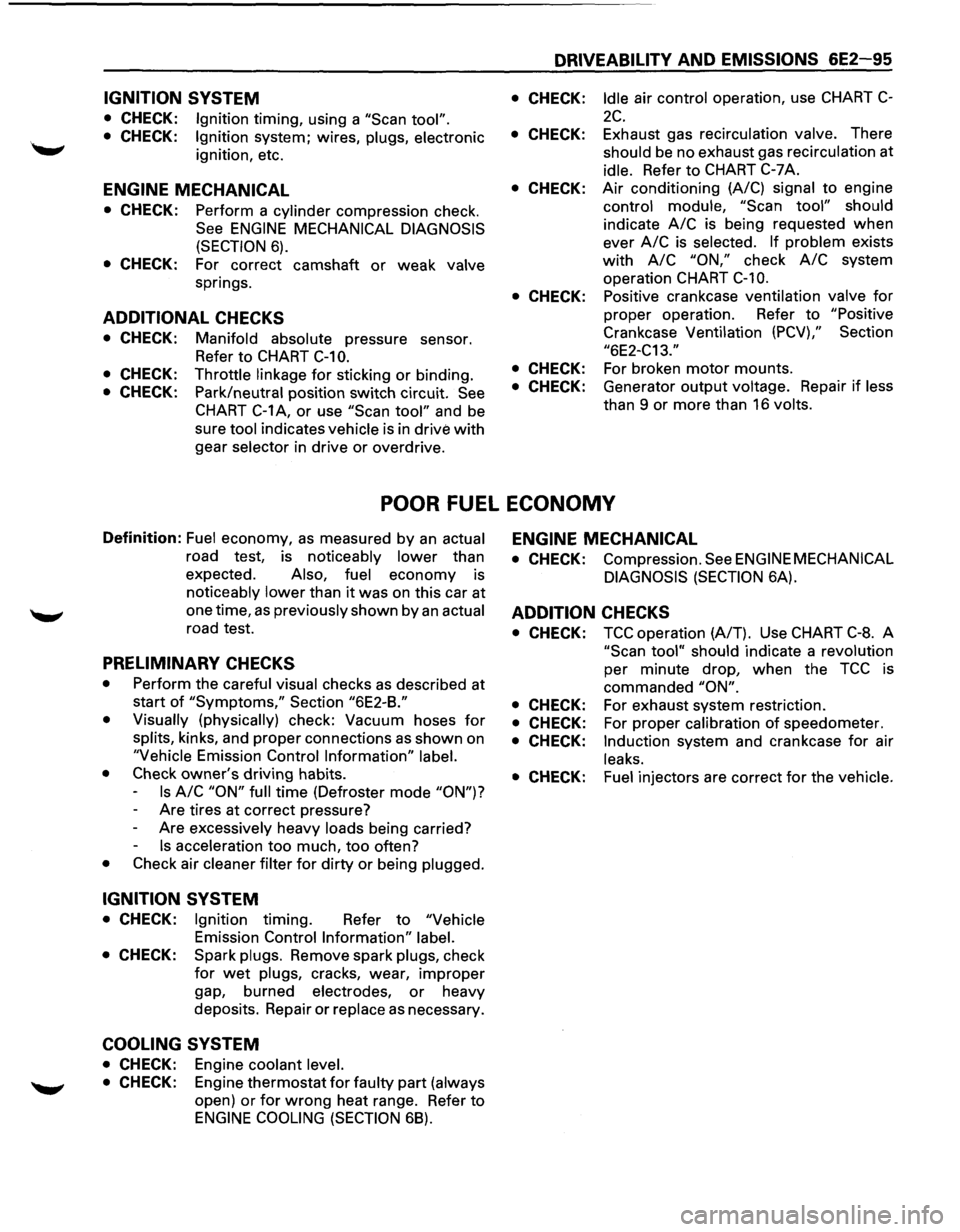
COOLING SYSTEM
• CHECK: Engine coolant level.
• CHECK: Engine thermostat for faulty part (always
open) or for wrong heat range. Refer to
ENGINE COOLING (SECTION 68).
ENGINE MECHANICAL
• CHECK: Compression. See ENGINE MECHANICAL
DIAGNOSIS
(SECTION 6A).
ADDITION CHECKS
• CHECK:
• CHECK:
• CHECK:
• CHECK:
• CHECK:
TCC operation (A/T). Use CHART C-8. A
"Scan tool" should indicate a revolution
per minute drop, when the TCC is
commanded
"ON".
For exhaust system restriction.
For proper
calibration of speedometer.
Induction system and crankcase for air
leaks.
Fuel
injectors are correct for the vehicle.
Page 792 of 1928
6E2-96 DRIVEABILITY AND EMISSIONS
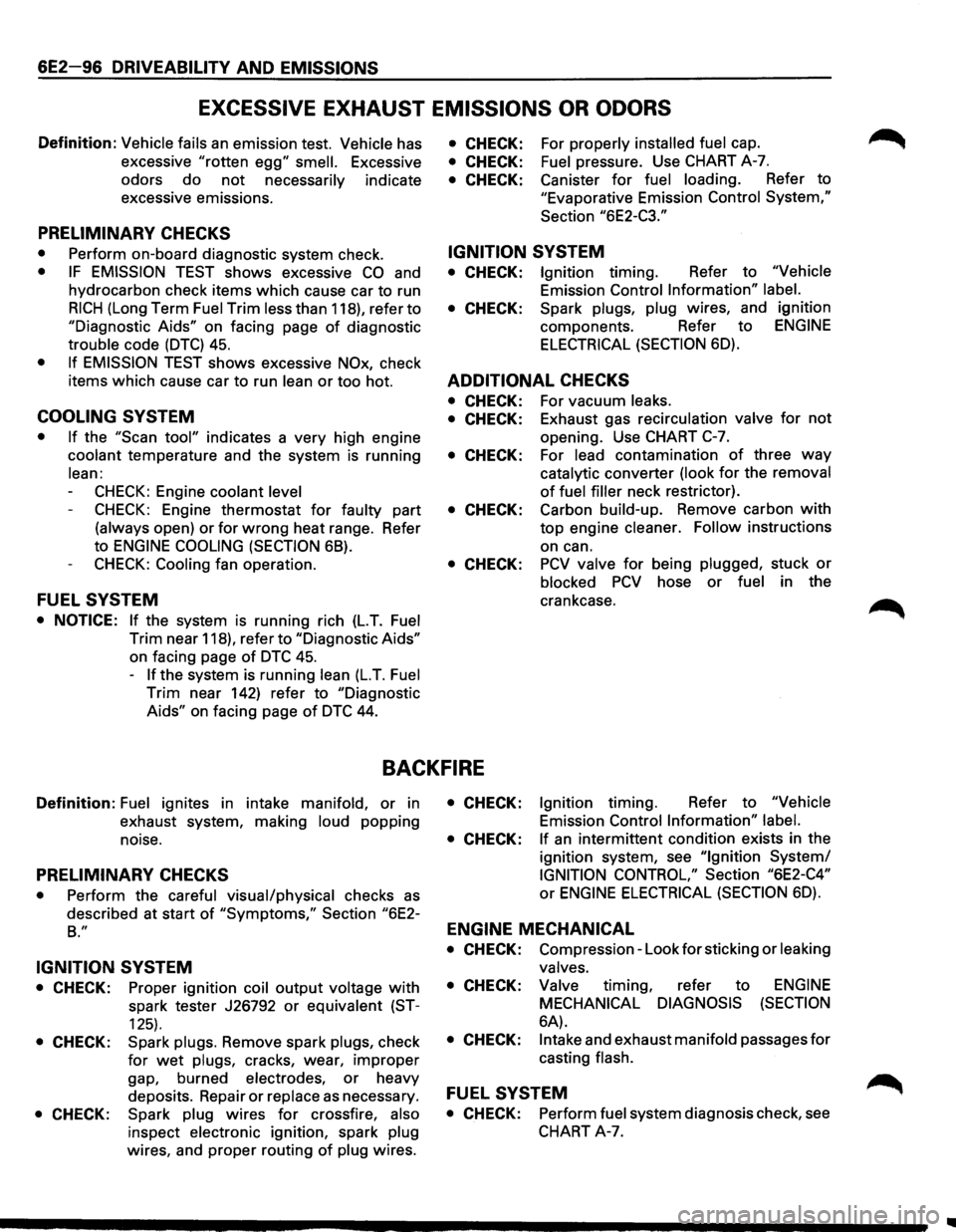
EXCESSIVE EXHAUST EMISSIONS OR ODORS
Definition: Vehicle fails an emission test. Vehicle has
excessive
"rotten egg" smell. Excessive
odors
do not necessarily indicate
excessive emissions.
PRELIMINARY CHECKS
• Perform on-board diagnostic system check.
• IF EMISSION TEST shows excessive CO and
hydrocarbon check items which cause car to run
RICH (Long Term Fuel Trim less than 118), refer to
"Diagnostic Aids" on facing page of diagnostic
trouble code (DTC) 45.
• If EMISSION TEST shows excessive NOx, check
items which cause car
to run lean or too hot.
COOLING SYSTEM
• If the "Scan tool" indicates a very high engine
coolant temperature and the system is running
lean:
CHECK: Engine coolant level
CHECK: Engine thermostat for faulty part
(always open) or for wrong heat range. Refer
to
ENGINE COOLING (SECTION 68).
CHECK: Cooling fan operation.
FUEL SYSTEM
• NOTICE: If the system is running rich (L.T. Fuel
Trim near 118), refer to "Diagnostic Aids"
on facing page
of DTC 45.
-
If the system is running lean (L.T. Fuel
Trim near 142) refer to "Diagnostic
Aids" on facing page of DTC 44.
• CHECK: For properly installed fuel cap.
• CHECK: Fuel pressure. Use CHART A-7.
• CHECK: Canister for fuel loading. Refer to
"Evaporative Emission Control System,"
Section
"6E2-C3."
IGNITION SYSTEM
• CHECK: Ignition timing. Refer to "Vehicle
Emission Control Information" label.
• CHECK: Spark plugs, plug wires, and ignition
components. Refer to
ENGINE
ELECTRICAL (SECTION 6D).
ADDITIONAL CHECKS
• CHECK: For vacuum leaks.
• CHECK: Exhaust gas recirculation valve for not
opening. Use CHART C-7.
• CHECK: For lead contamination of three way
catalytic converter (look for the removal
of fuel filler neck restrictor).
• CHECK: Carbon build-up. Remove carbon with
top engine cleaner. Follow instructions
on can.
• CHECK: PCV valve for being plugged, stuck or
blocked PCV hose or fuel in the
crankcase.
BACKFIRE
Definition: Fuel ignites in intake manifold, or in
exhaust system, making
loud popping
noise.
PRELIMINARY CHECKS
• Perform the careful visual/physical checks as
described at start of "Symptoms," Section "6E2-
B."
IGNITION SYSTEM
• CHECK: Proper ignition coil output voltage with
spark tester J26792 or equivalent (ST-
125).
• CHECK: Spark plugs. Remove spark plugs, check
for
wet plugs, cracks, wear, improper
gap, burned
electrodes, or heavy
deposits. Repair
or replace as necessary.
• CHECK: Spark plug wires for crossfire, also
inspect electronic ignition, spark plug
wires, and proper routing of plug wires.
• CHECK: Ignition timing. Refer to "Vehicle
Emission Control Information" label.
• CHECK: If an intermittent condition exists in the
ignition system, see
"Ignition System/
IGNITION CONTROL," Section "6E2-C4"
or ENGINE ELECTRICAL (SECTION 6D).
ENGINE MECHANICAL
• CHECK: Compression- Look for sticking or leaking
valves.
• CHECK: Valve timing, refer to ENGINE
MECHANICAL DIAGNOSIS (SECTION
6A).
• CHECK: Intake and exhaust manifold passages for
casting
flash.
FUEL SYSTEM
• CHECK: Perform fuel system diagnosis check, see
CHART A-7.
Page 893 of 1928
AUTOMATIC TRANSMISSION (4L30-E) 7A-21
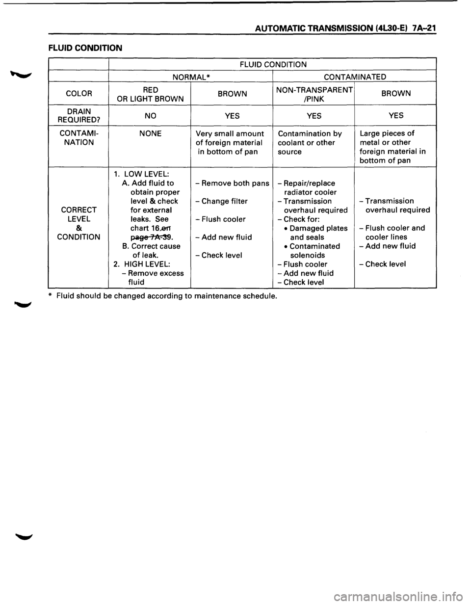
FLUID CONDITION
FLUID CONDITION
NORMAL* CONTAMINATED
COLOR
RED BROWN NON-TRANSPARENT BROWN OR LIGHT BROWN
/PINK
DRAIN NO
YES YES YES
REQUIRED?
CO NT AMI- NONE Very small amount Contamination by Large pieces of
NATION of foreign material coolant or other metal or other
in bottom of pan
source foreign material in
bottom of pan
1. LOW LEVEL:
A. Add fluid to -
Remove both pans -Repair/replace
obtain
proper radiator cooler
level
& check -Change filter -Transmission -Transmission
CORRECT for external overhaul required overhaul required
LEVEL leaks. See -Flush cooler -Check for:
& chart 16..811 • Damaged plates -Flush cooler and
CONDITION ~· -Add new fluid and seals cooler
lines
B. Correct cause • Contaminated -Add new fluid
of leak. -Check level solenoids
2. HIGH LEVEL: -Flush cooler -Check level
-Remove excess -Add new fluid
fluid -Check level
* Fluid should be changed according to maintenance schedule.
Page 913 of 1928
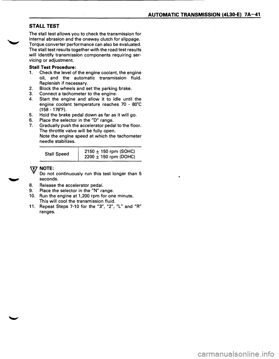
STALL TEST
The stall test allows you to check the transmission for
internal abrasion and the oneway clutch for slippage.
Torque converter performance can also be evaluated.
The
stall test results together with the road test results
will identify transmission components requiring ser
vicing or adjustment.
Stall Test Procedure:
1. Check the level of the engine coolant, the engine
oil, and the automatic transmission fluid.
Replenish
if necessary.
2. Block the wheels and set the parking brake.
3. Connect a tachometer to the engine.
4. Start the engine and allow it to idle until the
engine coolant temperature reaches
70 -8o·c
(158 -176.F).
5. Hold the brake pedal down as far as it will go.
6. Place the selector in the "D" range.
7. Gradually push the accelerator pedal to the floor.
The throttle valve
will be fully open.
Note the engine speed at which the tachometer
needle stabilizes.
Stall Speed
\fl NOTE:
2150 ± 150 rpm (SOHC)
2200 ± 150 rpm (DOHC)
VI Do not continuously run this test longer than 5
........, seconds.
8. Release the accelerator pedal.
9. Place the selector in the "N" range.
10. Run the engine at 1,200 rpm for one minute.
This
will cool the transmission fluid.
11. Repeat Steps 7-10 for the "3", "2", "L" and "R"
ranges.
AUTOMATIC TRANSMISSION (4L30-E) 7A-41
Page 914 of 1928
7 A-42 AUTOMATIC TRANSMISSION (4L30-E)
LINE PRESSURE TEST
The line pressure test checks oil pump and control
valve
pressure regulator valve function. It will also
detect oil leakage.
Line Pressure Test Procedure:
1. Check the level of the engine coolant, the engine
oil, and the automatic transmission fluid.
Replenish
if required.
2. Block the wheels and set the parking brake.
3. Remove the pressure detection plug at the left
side of the transmission case.
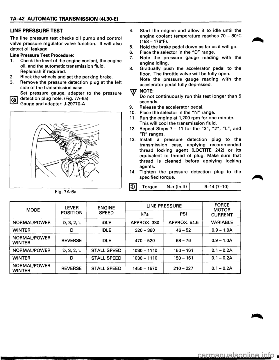
Set pressure gauge, adapter
to the pressure
l"iC\1 detection plug hole. (Fig. 7 A-6a)
~ Gauge and adapter: J-29770-A
Fig. 7A-6a
LEVER ENGINE
MODE
POSITION
SPEED
NORMAL/POWER D,3,2, L IDLE
WINTER D IDLE
NORMAL/POWER REVERSE IDLE WINTER
NORMAL/POWER
D,3,2,L STALL SPEED
WINTER D STALL SPEED
NORMAL/POWER REVERSE STALL SPEED WINTER
4.
5.
6.
7.
8.
9.
10.
11.
Start the engine and allow it to idle until the
engine
coolant temperature reaches 70 -80°C
(158-176°F).
Hold
the brake pedal down as far as it will go.
Place the selector in the "D" range.
Note the pressure gauge reading
with the
engine
idling.
Gradually
push the accelerator pedal to the
floor. The throttle valve will be fully open.
Note the pressure gauge reading
with the
accelerator
pedal fully depressed.
NOTE:
Do not continuously run this test longer than 5
seconds.
Release the accelerator pedal.
Place
the selector in the "N" range.
Run the engine at
1,200 rpm for one minute.
This
will cool the transmission fluid.
12. Repeat Steps 7-11 for the "3", "2", "L", and
"R" ranges.
13.
Install a pressure detection plug to the
transmission case,
applying recommended
thread
locking agent (LOCTITE 242) or its
equivalent to thread
of plug. Make sure that
thread is cleaned before applying locking
agents.
14. Tighten the pressure detection plug to the
specified torque.
~~~ Torque N·mOb·ft) / 9-14 (7-10)
LINE
PRESSURE FORCE
MOTOR kPa PSI CURRENT
APPROX. 380 APPROX. 54.6 VARIABLE
320-360 46-52 0.9 -1.0A
470-520 68-76 0.9 -1.0A
1030-1110 150-161 0.1-0.2A
1030-1110 150-161 0.1-0.2A
1450-1570 210-227 0.1-0.2A
•