cooling ISUZU TROOPER 1995 User Guide
[x] Cancel search | Manufacturer: ISUZU, Model Year: 1995, Model line: TROOPER, Model: ISUZU TROOPER 1995Pages: 1928
Page 65 of 1928
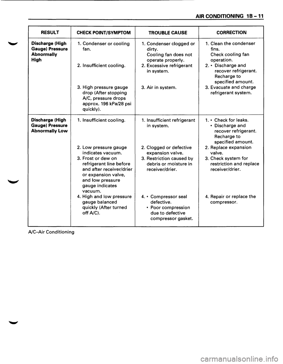
AIR CONDITIONING 1 B -11
RESULT CHECK POINT/SYMPTOM TROUBLE CAUSE CORRECTION
Discharge
(High 1. Condenser or cooling 1. Condenser clogged or 1. Clean the condenser
Gauge) Pressure fan. dirty. fins.
Abnormally Cooling fan does not Check cooling fan
High operate properly. operation.
2. Insufficient cooling. 2. Excessive refrigerant 2. • Discharge and
in system. recover
refrigerant.
Recharge
to
specified amount.
3. High pressure gauge 3. Air in system. 3. Evacuate and charge
drop (After stopping refrigerant system.
A/C, pressure
drops
approx. 196 kPa/28 psi
quickly).
Discharge (High 1. Insufficient cooling. 1. Insufficient refrigerant 1 .• Check for leaks.
Gauge)
Pressure in system. • Discharge and
Abnormally Low recover refrigerant.
Recharge
to
specified amount.
2. Low pressure gauge 2. Clogged or defective 2. Replace expansion
indicates vacuum.
expansion
valve. valve.
3. Frost or dew on 3. Restriction caused by 3. Check system for
refrigerant line before
debris or moisture in restriction
and replace
and after receiver/drier
receiver/drier. receiver/drier.
or expansion valve,
and low pressure
gauge indicates
vacuum.
4. High and low pressure 4. • Compressor seal 4. Repair or replace the
gauge balanced defective. compressor.
quickly (After turned • Poor
compression
off A/C). due to defective
compressor gasket.
A/C-Air Conditioning
Page 66 of 1928
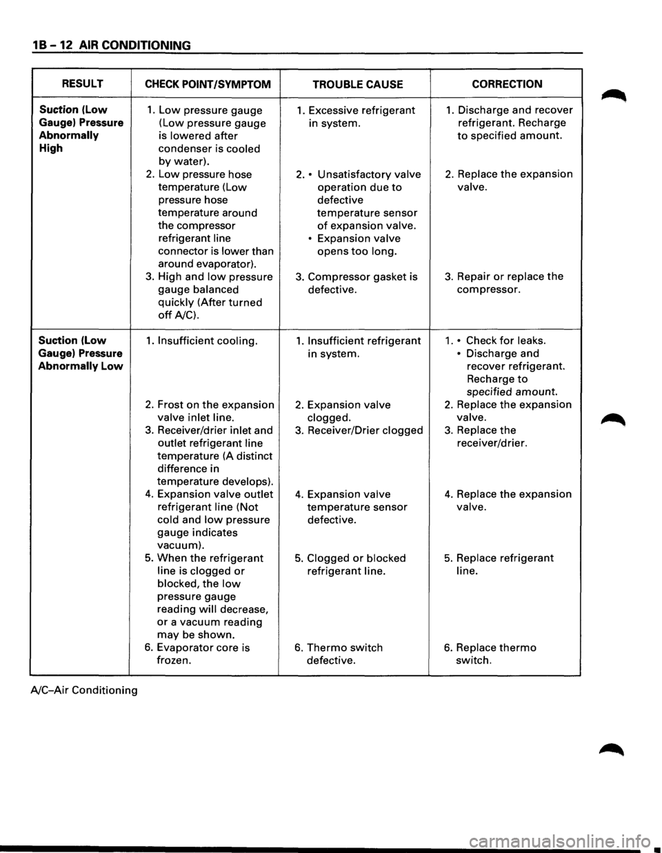
1 B -12 AIR CONDITIONING
RESULT CHECK POINT /SYMPTOM
TROUBLE CAUSE CORRECTION
Suction (low 1. Low pressure
gauge 1. Excessive refrigerant 1. Discharge and recover
Gauge) Pressure (Low pressure gauge
in system. refrigerant.
Recharge
Abnormally is lowered after to specified amount.
High condenser is cooled
by water).
2. Low pressure hose 2. • Unsatisfactory valve 2. Replace the expansion
temperature (Low operation due to valve.
pressure hose
defective
temperature around
temperature sensor
the compressor of expansion valve.
refrigerant line
• Expansion valve
connector is lower than opens too long.
around evaporator).
3. High and low pressure 3. Compressor gasket is 3. Repair or replace the
gauge balanced defective. compressor.
quickly (After turned
off A/C).
Suction (low 1. Insufficient cooling. 1. Insufficient refrigerant 1 .• Check for leaks.
Gauge) Pressure in system. • Discharge and
Abnormally Low recover refrigerant.
Recharge
to
specified amount.
2. Frost on the expansion 2. Expansion valve 2. Replace the expansion
valve inlet line.
clogged. valve.
3. Receiver/drier inlet and 3. Receiver/Drier clogged 3. Replace the
outlet refrigerant line receiver/drier.
temperature (A distinct
difference in
temperature
develops).
4. Expansion valve outlet 4. Expansion valve 4. Replace the expansion
refrigerant line (Not temperature sensor valve.
cold
and low pressure defective.
gauge indicates
vacuum).
5. When the refrigerant 5. Clogged or blocked 5. Replace refrigerant
line is clogged or refrigerant line. line.
blocked,
the low
pressure gauge
reading
will decrease,
or a vacuum reading
may be shown.
6. Evaporator core is 6. Thermo switch 6. Replace thermo
frozen.
defective. switch.
A/C-Air Conditioning
..
Page 67 of 1928
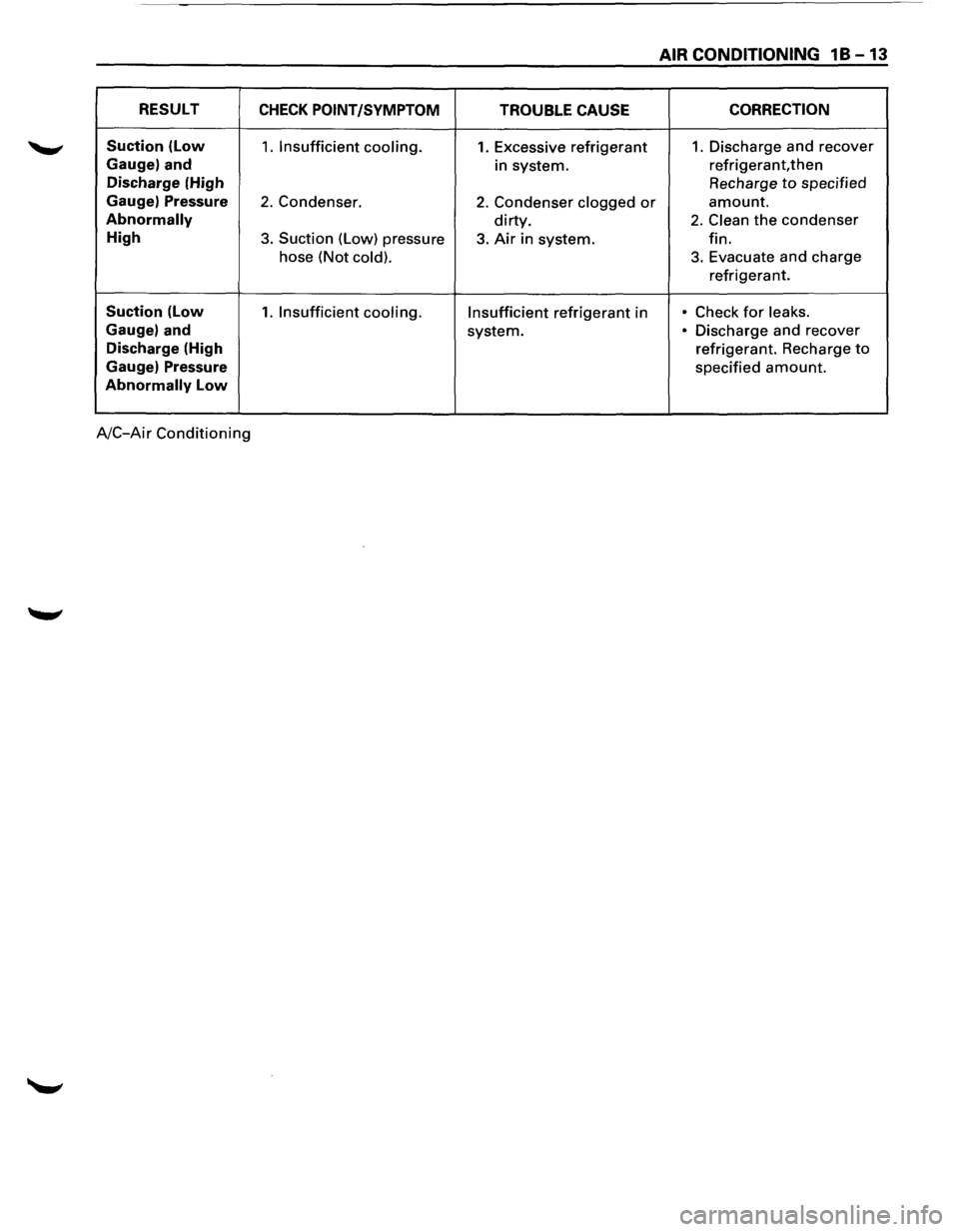
AIR CONDITIONING 1 B -13
RESULT CHECK POINT /SYMPTOM
TROUBLE CAUSE CORRECTION
Suction (low 1. Insufficient cooling. 1. Excessive refrigerant 1. Discharge
and recover
Gauge) and in system. refrigerant, then
Discharge
(High Recharge to specified
Gauge) Pressure 2. Condenser. 2. Condenser clogged or amount.
Abnormally dirty. 2. Clean the condenser
High 3. Suction (Low) pressure 3. Air in system. fin.
hose (Not
cold). 3. Evacuate and charge
refrigerant.
Suction (Low 1. Insufficient cooling. Insufficient refrigerant in • Check for leaks.
Gauge) and system. • Discharge and recover
Discharge (High refrigerant. Recharge to
Gauge) Pressure specified amount.
Abnormally Low
A/C-Air Conditioning
Page 90 of 1928
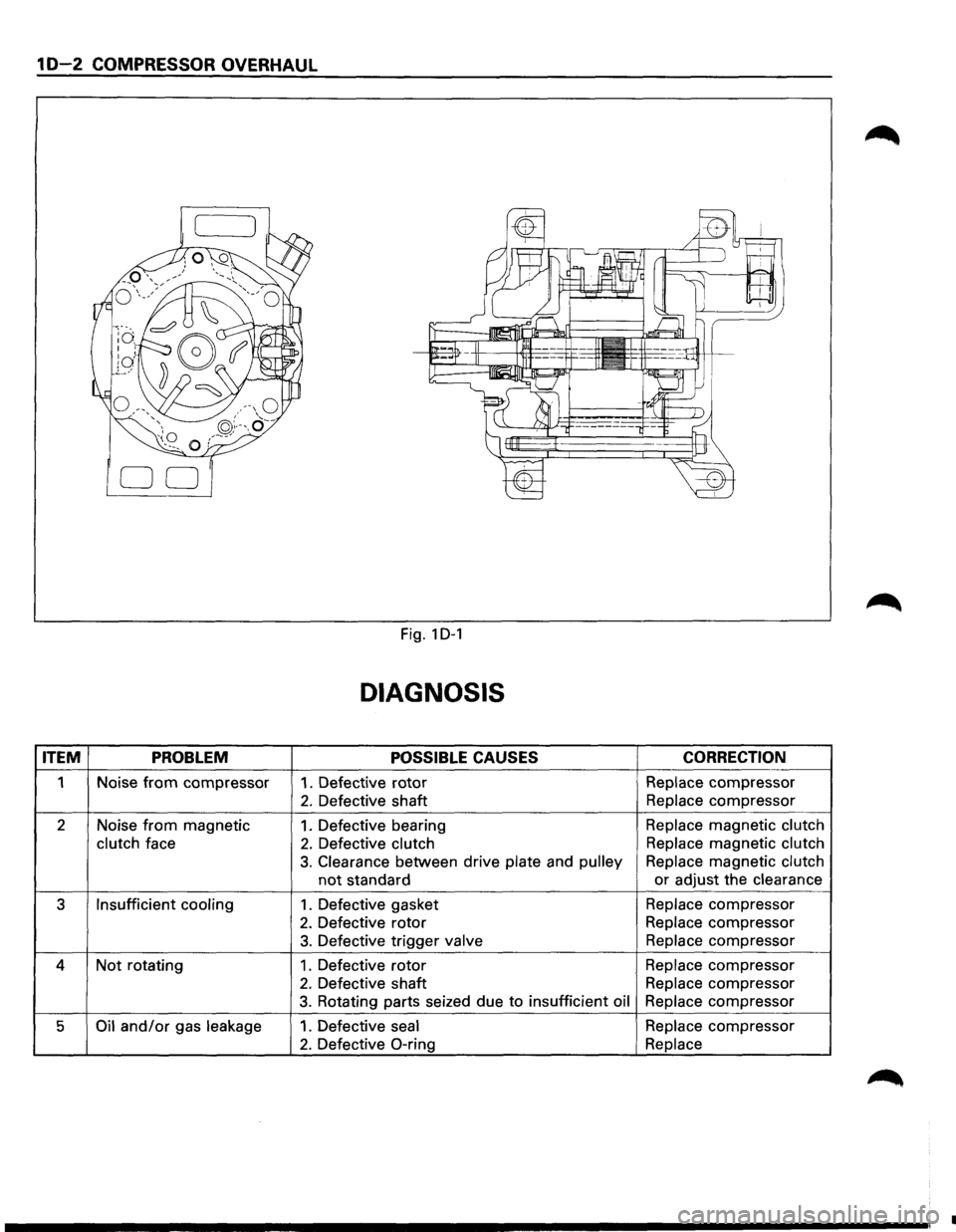
1 D-2 COMPRESSOR OVERHAUL
Fig. 1 D-1
DIAGNOSIS
ITEM PROBLEM POSSIBLE CAUSES CORRECTION
1
Noise from compressor 1. Defective rotor Replace compressor
2. Defective shaft Replace compressor
2 Noise
from magnetic 1. Defective bearing Replace magnetic clutch
clutch
face 2. Defective clutch Replace magnetic clutch
3. Clearance
between drive plate and pulley Replace magnetic clutch
not standard or adjust
the clearance
3
Insufficient cooling 1. Defective gasket Replace
compressor
2. Defective rotor Replace compressor
3. Defective trigger valve Replace compressor
4 Not rotating 1. Defective rotor Replace compressor
2. Defective shaft Replace compressor
3. Rotating parts seized due to insufficient oil Replace compressor
5 Oil and/or gas leakage 1. Defective seal Replace compressor
2. Defective 0-ring Replace
•
Page 144 of 1928
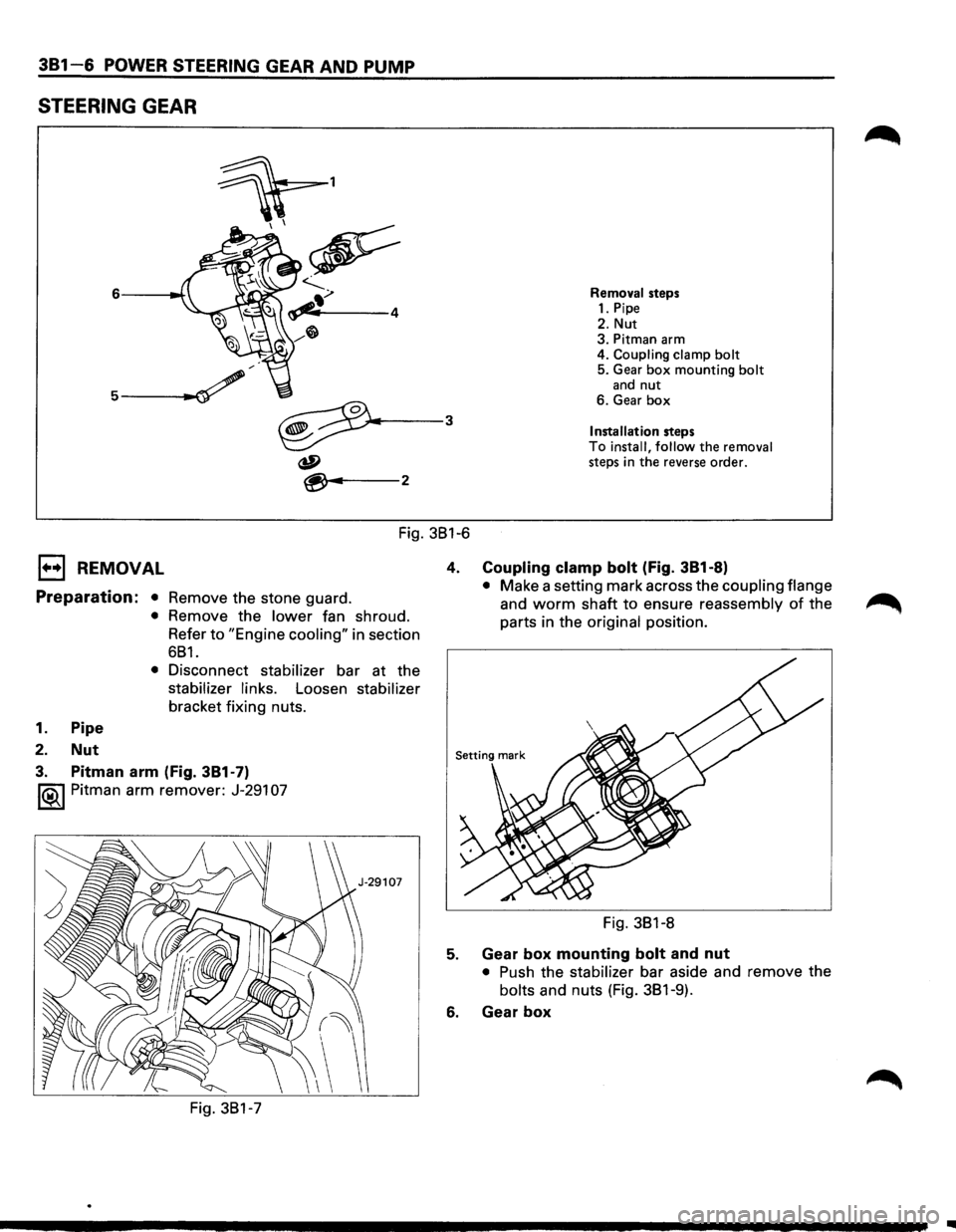
381-6 POWER STEERING GEAR AND PUMP
STEERING GEAR
Removal steps 1. Pipe
2. Nut 3. Pitman arm
4. Coupling clamp bolt 5. Gear box mounting bolt and nut 6. Gear box
Installation steps To install, follow the removal steps in the reverse order.
Fig. 381-6
EJ REMOVAL
Preparation: • Remove the stone guard.
1. Pipe
2. Nut
• Remove the lower fan shroud.
Refer to
"Engine cooling" in section
681.
• Disconnect stabilizer bar at the
stabilizer links. Loosen stabilizer
bracket fixing nuts.
3. Pitman arm (Fig. 381-7)
1®1 Pitman arm remover: J-291 07
Fig. 381-7 4.
Coupling clamp bolt (Fig.
381-8)
• Make a setting mark across the coupling flange
and worm shaft to ensure reassembly of the
parts in the
original position.
Fig. 381-8
5. Gear box mounting bolt and nut
• Push the stabilizer bar aside and remove the
bolts and nuts (Fig. 381-9).
6. Gear box
..
Page 499 of 1928
ENGINE DIAGNOSIS S-1
ENGINE
CONTENTS
Engine General Information . . . . . . . . . . . . . . . . . . . . . . . . . . . . . . . . . . . . . . . . . . . . . . . . . . . . . Section S
General
Engine Mechanical .................................................... Section SA
3.2L VS Engine ............................................................... Section SA1
Engine Cooling . . . . . . . . . . . . . . . . . . . . . . . . . . . . . . . . . . . . . . . . . . . . . . . . . . . . . . . . . . . . . . . . Section S8
Engine Fuel . . . . . . . . . . . . . . . . . . . . . . . . . . . . . . . . . . . . . . . . . . . . . . . . . . . . . . . . . . . . . . . . . . . Section SC
Engine Electrical . . . . . . . . . . . . . . . . . . . . . . . . . . . . . . . . . . . . . . . . . . . . . . . . . . . . . . . . . . . . . . Section SD
Driveability and Emissions . . . . . . . . . . . . . . . . . . . . . . . . . . . . . . . . . . . . . . . . . . . . . . . . . . . . Section SE2
Engine Exhaust . . . . . . . . . . . . . . . . . . . . . . . . . . . . . . . . . . . . . . . . . . . . . . . . . . . . . . . . . . . . . . . Section SF
SECTION 6
ENGINE GENERAL INFORMATION
CONTENTS
Description of Engine Section . . . . . . . . . . . . . . . . . . . . . . . . . . . . . . . . . . . . . . . . . . . . . . . . . . . . . . . . S-1
General Description . . . . . . . . . . . . . . . . . . . . . . . . . . . . . . . . . . . . . . . . . . . . . . . . . . . . . . . . . . . . . . . . . S-2
Engine Diagnosis . . . . . . . . . . . . . . . . . . . . . . . . . . . . . . . . . . . . . . . . . . . . . . . . . . . . . . . . . . . . . . . . . . . . S-2
DESCRIPTION OF ENGINE SECTION
SECTIONS-ENGINE GENERAL INFORMATION SECTION S8-ENGINE COOLING
General description
Engine cleanliness and care, and general information
on engine service are covered in this section.
Engine diagnosis
This section covers the components of the fuel,
ignition, and mechanical systems that could cause a
particular complaint, and then outlines repairs in a
logical sequence.
SECTION SA-ENGINE MECHANICAL
This section contains information on the mechanical
parts of the engine, such as cylinder block, cylinder
head, crankshaft, pistons, valve train, camshaft, and
engine
lubrication.
Overhaul
procedures, removal and replacement
procedures, and specifications are also covered.
Specific subsections are:
SA-GENERAL;
Disassembly and reassembly procedures,
inspection and repair procedures
off the vehicle.
6A 1-3.2L V6 ENGINE;
Removal
and replacement procedures on the
vehicle.
Engine cooling system components such as radiator,
engine
coolant pump, thermostat, and cooling fan, are
covered
in this section.
SECTION SC-ENGINE FUEL
This section contains information on all the parts of the
fuel system except the fuel injectors, or throttle body II
unit itself. Items covered are: fuel tank, fuel pump, fuel
filter,
and fuel lines. Specific sections are used for each
fuel system type:
Port
Injection fuel rail and injectors will be found in
Section
6E2.
SECTION SD-ENGINE ELECTRICAL
Items covered in this section are battery, generator,
starter, ignition
coil, spark plugs and wires.
Ignition system diagnosis will be found in Section 6E2
as a "C4" chart.
Specific sections are:
601 -Battery
602 - Cranking System
603 -Charging System
604 -Ignition System
Page 507 of 1928
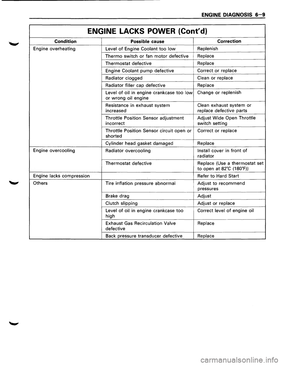
ENGINE DIAGNOSIS 6-9
ENGINE LACKS POWER (Cont'd)
Condition Possible cause Correction
Engine overheating
Level of Engine Coolant too low Replenish
Thermo switch or fan motor defective Replace
Thermostat defective Replace
Engine
Coolant pump defective Correct or replace
Radiator clogged
Clean or replace
Radiator
filler cap defective Replace
Level
of oil in engine crankcase too low Change or replenish
or
wrong oil engine
Resistance in exhaust system
Clean exhaust system or
increased replace
defective parts
Throttle Position Sensor adjustment Adjust
Wide Open Throttle
incorrect switch setting
Throttle Position Sensor circuit open
or Correct or replace
shorted
Cylinder head gasket damaged Replace
Engine overcooling
Radiator
overcooling Install cover
in front of
radiator
Thermostat defective Replace
(Use a thermostat set
to open at a2·c (180.F))
Engine
lacks compression Refer to Hard Start
Others Tire inflation pressure
abnormal Adjust to recommend
pressures
Brake drag Adjust
Clutch slipping Adjust or replace
Level
of oil in engine crankcase too Correct level of engine oil
high
Exhaust Gas
Recirculation Valve Replace
defective
Back pressure transducer defective
Replace
Page 578 of 1928
·,'
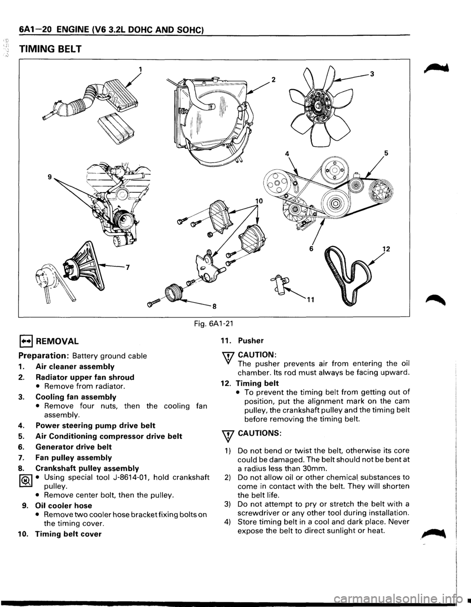
6A1-20 ENGINE (V6 3.2L DOHC AND SOHC)
TIMING BELT
1 3
2
6 12
~ ..
Fig. 6A1-21
1••1 REMOVAL
Preparation: Battery ground cable
1. Air cleaner assembly
2. Radiator upper fan shroud
• Remove from radiator.
3. Cooling fan assembly
• Remove four nuts, then the cooling fan
assembly.
4. Power steering pump drive belt
5. Air Conditioning compressor drive belt
6. Generator drive belt
7. Fan pulley assembly
8. Crankshaft pulley assembly
~ • Using special tool J-8614-01, hold crankshaft
~ pulley.
•
Remove center bolt, then the pulley.
9. Oil cooler hose
• Remove two cooler hose bracket fixing bolts on
the timing cover.
10. Timing belt cover 11.
Pusher
'IT7 CAUTION:
'if The pusher prevents air from entering the oil
chamber. Its rod must always be facing upward.
12. Timing belt
• To prevent the timing belt from getting out of
position, put the alignment mark on the cam
pulley, the crankshaft pulley and the timing belt
before removing the timing belt.
w CAUTIONS:
1) Do not bend or twist the belt, otherwise its core
could be damaged. The belt should not be bent at
a radius
less than 30mm.
2) Do not allow oil or other chemica[ substances to
come in contact with the belt. They will shorten
the
belt life.
3) Do not attempt to pry or stretch the belt with a
screwdriver or any other tool during installation.
4) Store timing belt in a cool and dark place. Never
expose the
belt to direct sunlight or heat. ~
•
Page 581 of 1928
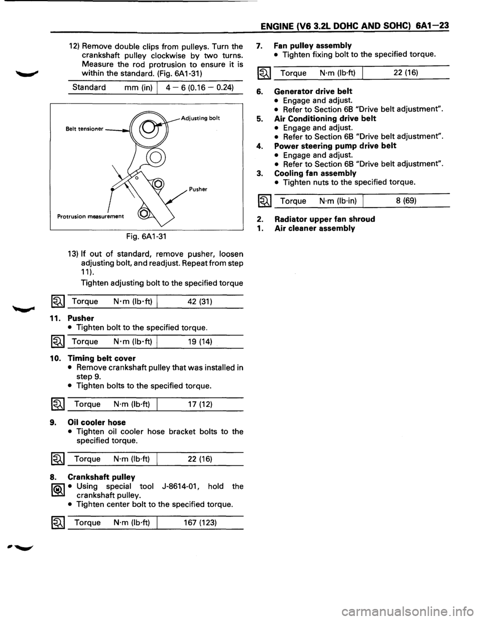
12) Remove double clips from pulleys. Turn the
crankshaft
pulley clockwise by two turns.
Measure the rod protrusion to ensure
it is
within the standard. (Fig. 6A 1-31)
Standard
mm (in) I 4 - 6 (0.16 -0.24)
Adjusting bolt
Pusher
Fig. 6A1-31
13) If out of standard, remove pusher, loosen
adjusting bolt, and readjust. Repeat from step
11 ).
Tighten adjusting bolt to the specified torque
1~1 Torque N·m (lb·ft) I 42 (31)
11. Pusher
• Tighten bolt to the specified torque.
1~1 Torque N·m (lb·ft) I 19 (14)
10. Timing belt cover
• Remove crankshaft pulley that was installed in
step
9.
• Tighten bolts to the specified torque.
~~~ Torque N·m (lb·ft) I 17 (12)
9. Oil cooler hose
• Tighten oil cooler hose bracket bolts to the
specified torque.
~~~ Torque N·m (lb·ft) I 22 (16)
8. Crankshaft pulley
l"iQ\1 • Using special tool J-8614-01, hold the
~ crankshaft pulley.
•
Tighten center bolt to the specified torque.
1~1 Torque N·m (lb·ft) 167 (123)
ENGINE (V6 3.2L DOHC AND SOHC) 6A1-23
7. Fan pulley assembly
• Tighten fixing bolt to the specified torque.
~~~ Torque N·m (lb·ft) 22 (16)
6. Generator drive belt
• Engage and adjust.
• Refer to Section 68 "Drive belt adjustment".
5. Air Conditioning drive belt
• Engage and adjust.
• Refer to Section 68 "Drive belt adjustment".
4. Power steering pump drive belt
• Engage and adjust.
• Refer to Section 68 "Drive belt adjustment".
3. Cooling fan assembly
• Tighten nuts to the specified torque.
~~~ Torque N·m (lb·in) I 8 (69)
2. Radiator upper fan shroud
1. Air cleaner assembly
Page 582 of 1928
, r;
6A 1-24 ENGINE (V6 3.2L DOHC AND SOHC)
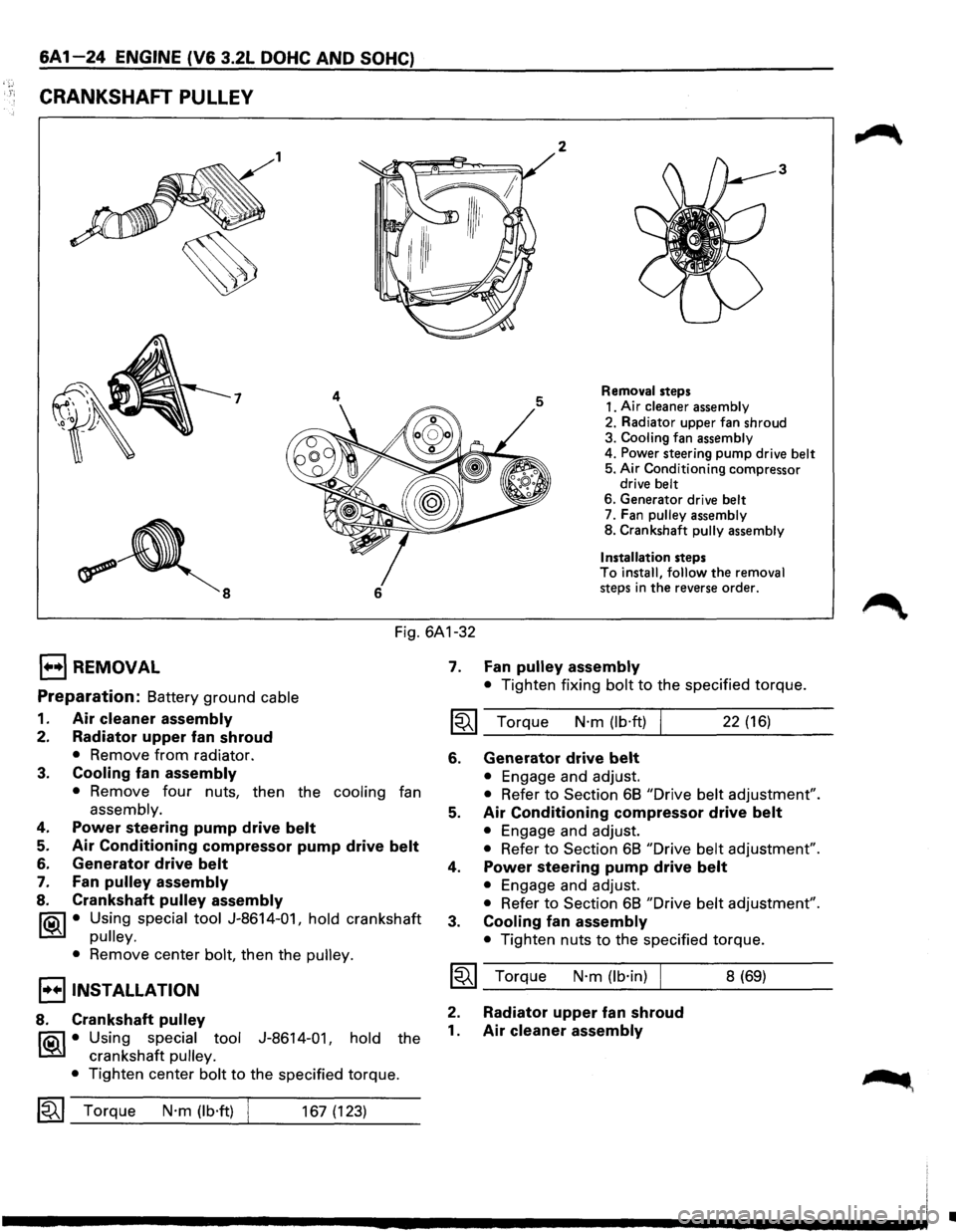
CRANKSHAFT PULLEY
1 2
7 4
6
3
Removal steps
1. Air
cleaner assembly
2. Radiator upper fan shroud
3. Cooling fan assembly
4. Power steering pump drive belt 5. Air Conditioning compressor
drive belt
6. Generator drive belt 7. Fan pulley assembly
8. Crankshaft pully assembly
Installation
steps To install, follow the removal steps in the reverse order.
Fig. 6A1-32
E) REMOVAL
Preparation: Battery ground cable
1. Air cleaner assembly
2. Radiator upper fan shroud
• Remove from radiator.
3. Cooling fan assembly
• Remove four nuts, then the cooling fan
assembly.
4. Power steering pump drive belt
5. Air Conditioning compressor pump drive belt
6. Generator drive belt
7. Fan pulley assembly
8. Crankshaft pulley assembly
IQil • Using special tool J-8614-01, hold crankshaft
I.:Sil pulley.
•
Remove center bolt, then the pulley.
I••IINSTALLATION
8. Crankshaft pulley
IQil • Using special tool J-8614-01, hold the
I.:Sil crankshaft pulley.
•
Tighten center bolt to the specified torque.
1~1 Torque N·m (lb·ft) 167 (123)
7. Fan pulley assembly
• Tighten fixing bolt to the specified torque.
1~1 Torque N·m (lb·ft) 22 (16)
6. Generator drive belt
• Engage and adjust.
• Refer to Section 68 "Drive belt adjustment".
5. Air Conditioning compressor drive belt
• Engage and adjust.
• Refer to Section 68 "Drive belt adjustment".
4. Power steering pump drive belt
• Engage and adjust.
• Refer to Section 68 "Drive belt adjustment".
3. Cooling fan assembly
• Tighten nuts to the specified torque.
~~~ Torque N·m (lb·in) I
2. Radiator upper fan shroud
1. Air cleaner assembly
8 (69)
•