tire pressure ISUZU TROOPER 1995 Workshop Manual
[x] Cancel search | Manufacturer: ISUZU, Model Year: 1995, Model line: TROOPER, Model: ISUZU TROOPER 1995Pages: 1928
Page 21 of 1928
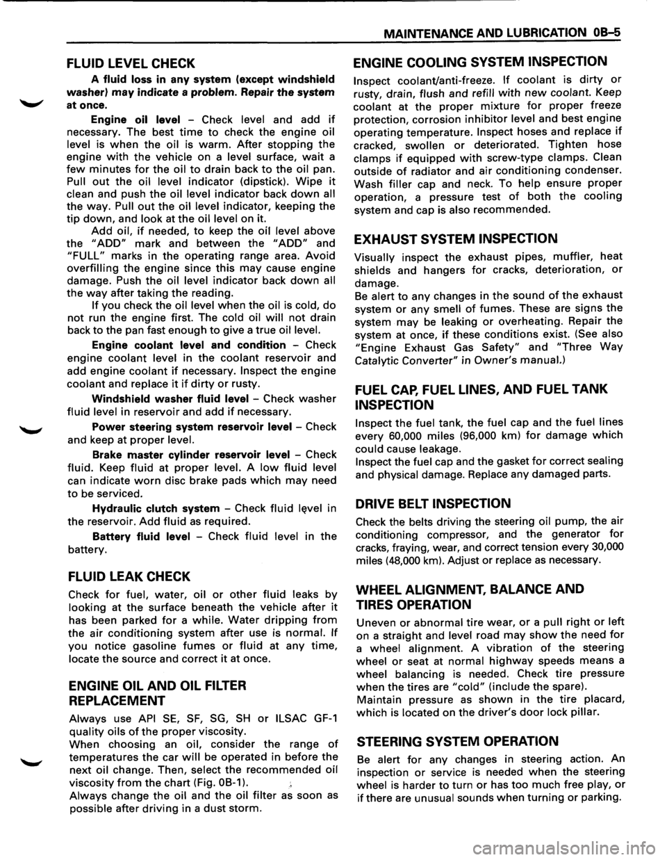
FLUID LEVEL CHECK
A fluid loss in any system (except windshield
washer) may indicate a problem. Repair the system
at once.
Engine
oil level -Check level and add if
necessary. The best time to check the engine oil
level is
when the oil is warm. After stopping the
engine with the vehicle on a level surface, wait a
few minutes for the oil to drain back to the oil pan.
Pull
out the oil level indicator (dipstick). Wipe it
clean and push the oil level indicator back down all
the
way. Pull out the oil level indicator, keeping the
tip down, and look at the oil level on it.
Add oil, if needed, to keep the oil level above
the
"ADD" mark and between the "ADD" and
"FULL" marks in the operating range area. Avoid
overfilling the engine since this may cause engine
damage. Push
the oil level indicator back down all
the
way after taking the reading.
If you check the oil level when the oil is cold, do
not run the engine first. The cold oil will not drain
back
to the pan fast enough to give a true oil level.
Engine coolant level and condition -Check
engine coolant level in the coolant reservoir and
add engine
coolant if necessary. Inspect the engine
coolant and replace it if dirty or rusty.
Windshield washer fluid level -Check washer
fluid level in reservoir and add if necessary.
Power steering system reservoir level-Check
and keep at
proper level.
Brake master cylinder reservoir level -Check
fluid. Keep fluid at proper level. A low fluid level
can indicate
worn disc brake pads which may need
to be serviced.
Hydraulic clutch system -Check fluid l~vel in
the reservoir.
Add fluid as required.
Battery fluid level -Check fluid level in the
battery.
FLUID LEAK CHECK
Check for fuel, water, oil or other fluid leaks by
looking at the surface beneath the vehicle after it
has been parked for a while. Water dripping from
the air conditioning system after use is normal. If
you notice gasoline fumes or fluid at any time,
locate the source and correct it at once.
ENGINE OIL AND OIL FILTER
REPLACEMENT
Always use API SE, SF, SG, SH or ILSAC GF-1
quality oils of the proper viscosity.
When choosing an oil, consider the range of
temperatures the car will be operated in before the
next oil change. Then, select the recommended oil
viscosity
from the chart (Fig. OB-1).
Always change the oil and the oil filter as soon as
possible after driving in a dust storm.
MAINTENANCE AND LUBRICATION OB-5
ENGINE COOLING SYSTEM INSPECTION
Inspect coolant/anti-freeze. If coolant is dirty or
rusty, drain, flush and refill with new coolant. Keep
coolant at the proper mixture for proper freeze
protection,
corrosion inhibitor level and best engine
operating temperature.
Inspect hoses and replace if
cracked, swollen or deteriorated. Tighten hose
clamps if equipped with screw-type clamps. Clean
outside of radiator and air conditioning condenser.
Wash
filler cap and neck. To help ensure proper
operation, a pressure test of both the cooling
system and cap is also recommended.
EXHAUST SYSTEM INSPECTION
Visually inspect the exhaust pipes, muffler, heat
shields and hangers
for cracks, deterioration, or
damage.
Be alert to any changes in the sound of the exhaust
system
or any smell of fumes. These are signs the
system may be leaking or overheating. Repair the
system at once,
if these conditions exist. (See also
"Engine Exhaust Gas Safety" and "Three Way
Catalytic Converter" in Owner's manual.)
FUEL CAP, FUEL LINES, AND FUEL TANK
INSPECTION
Inspect the fuel tank, the fuel cap and the fuel lines
every
60,000 miles (96,000 km) for damage which
could cause leakage.
Inspect the fuel cap and the gasket for correct sealing
and physical damage. Replace any damaged parts.
DRIVE BELT INSPECTION
Check the belts driving the steering oil pump, the air
conditioning compressor, and the generator
for
cracks, fraying, wear, and correct tension every 30,000
miles (48,000 km). Adjust or replace as necessary.
WHEEL ALIGNMENT, BALANCE AND
TIRES OPERATION
Uneven or abnormal tire wear, or a pull right or left
on a straight and level road may show the need for
a wheel alignment. A vibration of the steering
wheel or seat at normal highway speeds means a
wheel balancing is needed. Check tire pressure
when the tires are "cold" (include the spare).
Maintain pressure as shown in the tire placard,
which is located on the driver's door lock pillar.
STEERING SYSTEM OPERATION
Be alert for any changes in steering action. An
inspection
or service is needed when the steering
wheel is harder
to turn or has too much free play, or
if there are unusual sounds when turning or parking.
Page 28 of 1928
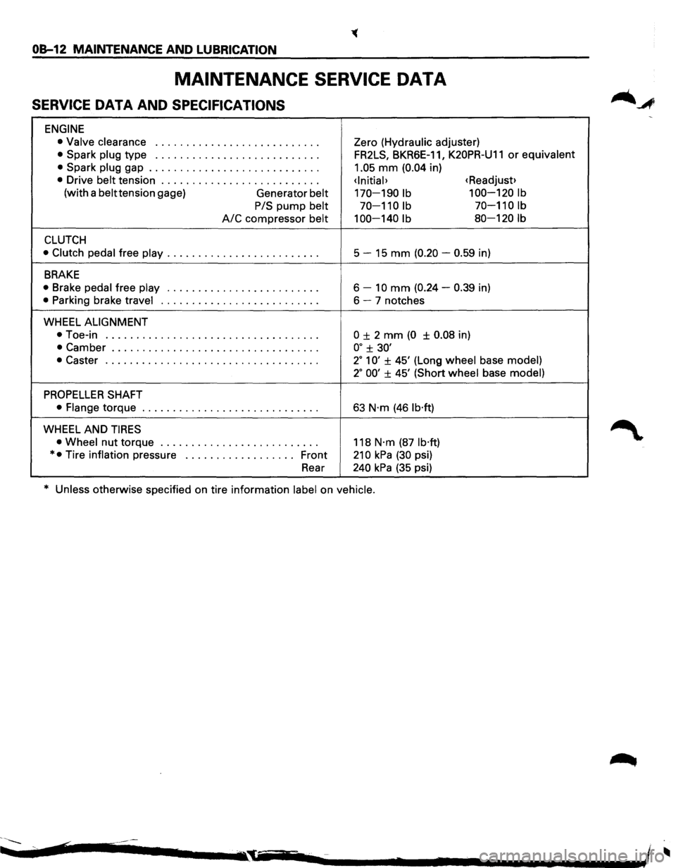
OB-12 MAINTENANCE AND LUBRICATION
MAINTENANCE SERVICE DATA
SERVICE DATA AND SPECIFICATIONS
ENGINE
• Valve clearance I o o I I I 0 0 0 I 0 o o o o o I 0 o o o 0 0 o o o o Zero (Hydraulic adjuster)
• Spark plug type I I o 0 I o 0 I I I 0 o o o I 0 I o o 0 0 0 o o 0 0 0 FR2LS, BKR6E-1 1, K20PR-U11 or equivalent
•
Spark plug gap ............................ 1.05 mm (0.04 in)
• Drive belt tension ..........................
(with a belttension gage)
Generator belt 170-190 lb 100-120 lb
PIS
pump belt 70-110 lb 70-110 lb
A/C compressor belt 100-140 lb 80-120 lb
CLUTCH
• Clutch pedal free play ......................... 5 -15 mm (0.20 -0.59 in)
BRAKE
• Brake pedal free play o o o o o o o o 0 0 o o o o o 0 0 o o 0 I o o o o 6 -10 mm (0.24 -0.39 in)
• Parking brake travel ••••••••••••••••••\
•• 0 ••••• 6-7 notches
WHEEL
ALIGNMENT
•
Toe-in 0 0 o o 0 0 I 0 0 o o o o 0 0 0 0 o o o o I 0 0 o o 0 0 o o o o 0 I 0 0 ± 2 mm (0 ± 0.08 in)
• Camber .................................. oo ± 30'
•
Caster o o o 0 0 0 0 o o o o o o I 0 0 o o o o 0 0 o o o o 0 o o o o o 0 0 o 2° 1 0' ± 45' (Long wheel base model)
2° 00' ± 45' (Short wheel base model)
PROPELLER SHAFT
• Flange torque ••••••••••••••••••\
•• 0' ••• 0 ••• 63 N·m (46 lb·ft)
WHEEL AND TIRES
• Wheel nut torque o o o o 0 0 o o o o o o o o o o o I o o o o 0 0 0 o 118 N·m (87 lb·ft)
* • Tire inflation pressure •••••••••••••• 0 ••• Front 21 0 kPa (30 psi)
Rear
240 kPa (35 psi)
* Unless otherwise specified on tire information label on vehicle.
~~-.... ¢ .............. .-I ~ -.,~iii~-..--. ....... 2 ........ -. .................. ~~ - I
Page 121 of 1928
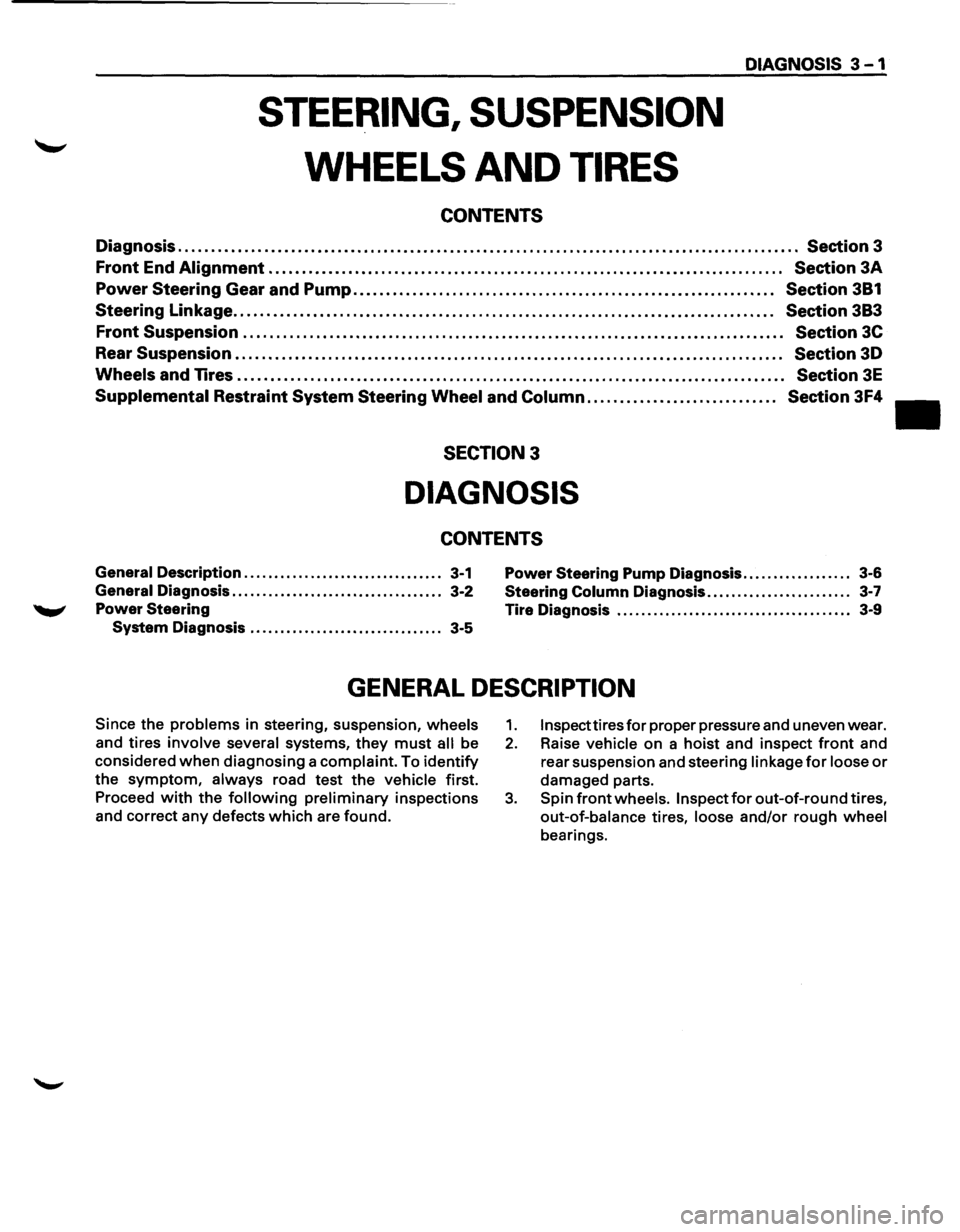
DIAGNOSIS 3 -1
STEERING, SUSPENSION
WHEELS AND TIRES
CONTENTS
Diagnosis.............................. . . . . . . . . . . . . . . . . . . . . . . . . . . . . . . . . . . . . . . . . . . . . . . . . . . . . . . . . . . . . . . . . Section 3
Front End
Alignment . . . . . . . . . . . . . . . . . . . . . . . . . . . . . . . . . . . . . . . . . . . . . . . . . . . . . . . . . . . . . . . . . . . . . . . . . . . . . . Section 3A
Power Steering Gear and Pump ................................................................ Section 381
Steering Linkage
........................................................................\
.......... Section 383
Front Suspension . . . . . . . . . . . . . . . . . . . . . . . . . . . . . . . . . . . . . . . . . . . . . . . . . . . . . . . . . . . . . . . . . . . . . . . . . . . . . . . . . . Section
3C
Rear Suspension . . . . . . . . . . . . . . . . . . . . . . . . . . . . . . . . . . . . . . . . . . . . . . . . . . . . . . . . . . . . . . . . . . . . . . . . . . . . . . . . . . . Section 3D
Wheels and
lires . . . . . . . . . . . . . . . . . . . . . . . . . . . . . . . . . . . . . . . . . . . . . . . . . . . . . . . . . . . . . . . . . . . . . . . . . . . . . . . . . . . Section 3E
Supplemental Restraint System Steering Wheel and Column............................. Section 3F4
SECTION 3
DIAGNOSIS
CONTENTS
General Description ................................. 3-1 Power Steering Pump Diagnosis. . . . . . . . . . . . . . . . . . 3-6
General Diagnosis . . . . . . . . . . . . . . . . . . . . . . . . . . . . . . . . . . . 3-2
Steering Column Diagnosis ........................ 3-7
"-"' Power Steering Tire Diagnosis . . . . . . . . . . . . . . . . . . . . . . . . . . . . . . . . . . . . . . . 3-9
System Diagnosis .. .. . . . . . .. . . . .. .. . . . .. .. . . . . . . . 3-5
GENERAL DESCRIPTION
Since the problems in steering, suspension, wheels
and tires
involve several systems, they must all be
considered
when diagnosing a complaint. To identify
the symptom, always road test the vehicle first.
Proceed
with the following preliminary inspections
and correct
any defects which are found.
1. lnspecttires for proper pressure and uneven wear.
2. Raise vehicle on a hoist and inspect front and
rear suspension and steering
linkage for loose or
damaged parts.
3. Spin front wheels. Inspect for out-of-round tires,
out-of-balance tires,
loose and/or rough wheel
bearings.
Page 122 of 1928
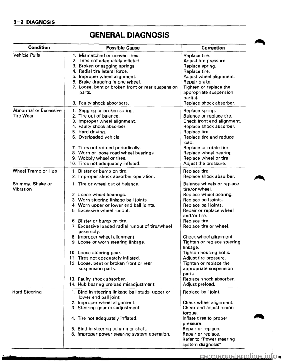
3-2 DIAGNOSIS
GENERAL DIAGNOSIS
Condition Possible Cause Correction
Vehicle
Pulls 1. Mismatched or uneven tires. Replace tire.
2. Tires not adequately inflated. Adjust tire pressure.
3. Broken or sagging springs. Replace spring.
4. Radial tire lateral force. Replace tire.
5. Improper wheel alignment. Adjust wheel alignment.
6. Brake dragging in one wheel. Repair brake.
7. Loose, bent or broken front or rear suspension Tighten or replace the
parts. appropriate suspension
part(s).
8. Faulty shock absorbers. Replace shock absorber.
Abnormal or Excessive 1. Sagging or broken spring. Replace spring.
Tire Wear
2. Tire out of balance. Balance or replace tire.
3. Improper wheel alignment. Check front end alignment.
4. Faulty shock absorber. Replace shock absorber.
5. Hard driving. Replace tire.
6. Overloaded vehicle. Replace tire
and reduce
load.
7. Tires not rotated periodically. Replace or rotate
tire.
8. Worn or loose road wheel bearings. Replace wheel bearing.
9. Wobbly wheel or tires. Replace wheel or tire.
10. Tires not adequately inflated. Adjust the pressure.
Wheel Tramp or Hop 1. Blister or bump on tire. Replace tire.
2. Improper shock absorber operation. Replace shock absorber.
Shimmy,
Shake or 1. Tire or wheel out of balance. Balance
wheels or replace
Vibration tire/or wheel.
2. Loose wheel bearings. Replace wheel bearing.
3. Worn steering linkage ball joints. Replace ball joints.
4. Worn upper or lower end ball joints. Replace ball joints.
5. Excessive wheel runout. Repair or replace
wheel
and/or tire.
6. Blister or bump on tire. Replace tire.
7. Excessive loaded radial runout of tire/wheel Replace tire or wheel.
assembly.
8. Improper wheel alignment. Check
wheel alignment.
9. Loose or worn steering linkage. Tighten or replace steering
linkage.
10. Loose steering gear. Tighten
housing bolts.
11. Tires not adequately inflated. Adjust tire pressure.
12. Loose, bent or broken front or rear Tighten or replace the
suspension parts. appropriate suspension
parts.
13. Faulty shock absorber. Replace shock absorber.
14. Hub bearing preload misadjustment. Adjust preload.
Hard Steering 1. Bind in steering linkage ball studs, upper or Replace ball joint.
lower end ball joint.
2. Improper wheel alignment. Check wheel alignment.
3. Steering gear misadjustment. Check and adjust pinion
torque.
4. Tire not adequately inflated. Inflate tires to proper
pressure.
5. Bind in steering column or shaft. Repair or replace.
6. Improper power steering
system operation. Repair or replace.
Refer to "Power steering
system diagnosis"
'· •
Page 123 of 1928
DIAGNOSIS 3-3
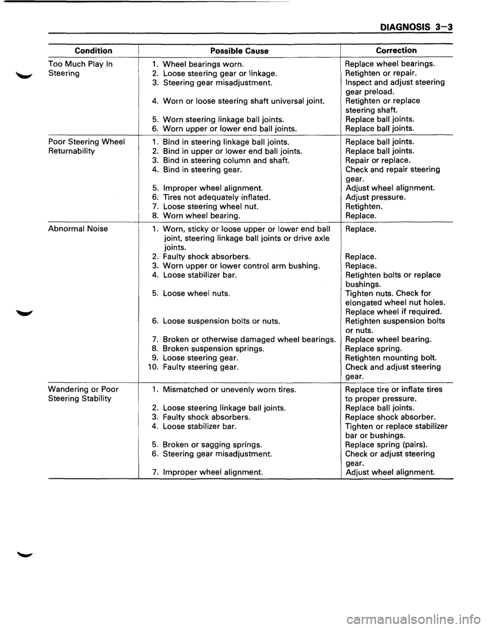
Condition Possible Cause Correction
Too
Much Play In 1. Wheel bearings worn. Replace wheel bearings.
Steering
2. Loose steering gear or linkage. Retighten or repair.
3. Steering
gear misadjustment. Inspect and adjust steering
gear preload.
4. Worn or loose steering shaft universal joint. Retighten or replace
steering shaft.
5. Worn steering linkage ball joints. Replace ball joints.
6. Worn upper or lower end ball joints. Replace ball joints.
Poor Steering
Wheel 1. Bind in steering linkage ball joints. Replace ball joints.
Returnability 2. Bind
in upper or lower end ball joints. Replace ball joints.
3. Bind
in steering column and shaft. Repair
or replace.
4. Bind in steering gear. Check and repair steering
gear.
5. Improper wheel alignment. Adjust wheel alignment.
6. Tires not adequately
inflated. Adjust
pressure.
7. Loose steering wheel nut. Retighten.
8. Worn wheel bearing.
Replace.
Abnormal Noise
1. Worn, sticky or loose upper or lower end ball Replace.
joint, steering linkage
ball joints or drive axle
joints.
2. Faulty shock absorbers.
Replace.
3. Worn upper or lower control arm bushing.
Replace.
4. Loose stabilizer bar. Retighten bolts or replace
bushings.
5. Loose wheel nuts. Tighten nuts. Check for
elongated wheel nut holes.
Replace
wheel if required.
6. Loose suspension bolts or nuts. Retighten suspension bolts
or nuts.
7. Broken or otherwise damaged wheel bearings. Replace wheel bearing.
8. Broken suspension springs. Replace spring.
9. Loose steering gear. Retighten mounting bolt.
10. Faulty steering gear. Check and adjust steering
gear.
Wandering
or Poor 1. Mismatched or unevenly worn tires. Replace tire or inflate tires
Steering
Stability to proper pressure.
2. Loose steering linkage ball joints. Replace ball joints.
3. Faulty shock absorbers. Replace shock absorber.
4. Loose stabilizer bar. Tighten or replace stabilizer
bar or bushings.
5. Broken or sagging springs. Replace spring (pairs).
6. Steering gear misadjustment. Check or adjust steering
gear.
7. Improper wheel alignment.
Adjust wheel alignment.
Page 124 of 1928
3-4 DIAGNOSIS
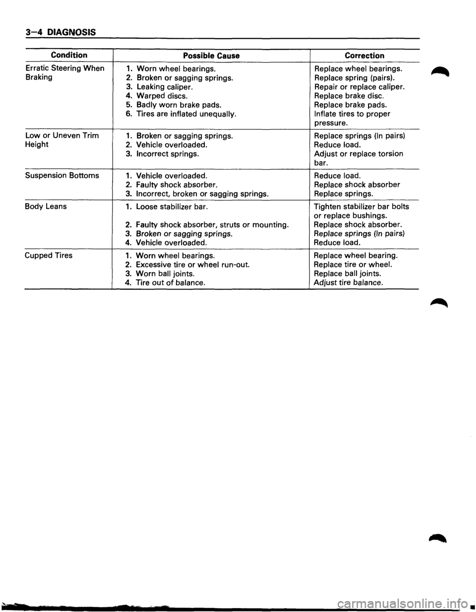
Condition Possible Cause Correction
Erratic Steering When 1. Worn wheel bearings. Replace wheel bearings.
Braking
2. Broken or sagging springs. Replace spring (pairs).
3. Leaking caliper. Repair or replace caliper.
4. Warped discs. Replace brake disc.
5. Badly worn brake pads. Replace brake pads.
6. Tires are inflated unequally. Inflate tires to proper
pressure.
Low or Uneven Trim
1. Broken or sagging springs. Replace springs (In pairs)
Height
2. Vehicle overloaded. Reduce load.
3. Incorrect springs. Adjust or replace torsion
bar.
Suspension Bottoms
1. Vehicle overloaded. Reduce load.
2. Faulty shock absorber. Replace shock absorber
3. Incorrect, broken or sagging springs. Replace springs.
Body Leans
1. Loose stabilizer bar. Tighten stabilizer bar bolts
or replace bushings.
2. Faulty shock
absorber, struts or mounting. Replace shock absorber.
3. Broken or sagging springs. Replace springs (In pairs)
4. Vehicle overloaded. Reduce load.
Cupped Tires 1. Worn wheel bearings. Replace wheel bearing.
2. Excessive tire or wheel run-out. Replace tire or wheel.
3. Worn ball joints. Replace ball joints.
4. Tire out of balance. Adjust tire balance.
•
Page 129 of 1928
DIAGNOSIS 3-9
TIRE DIAGNOSIS
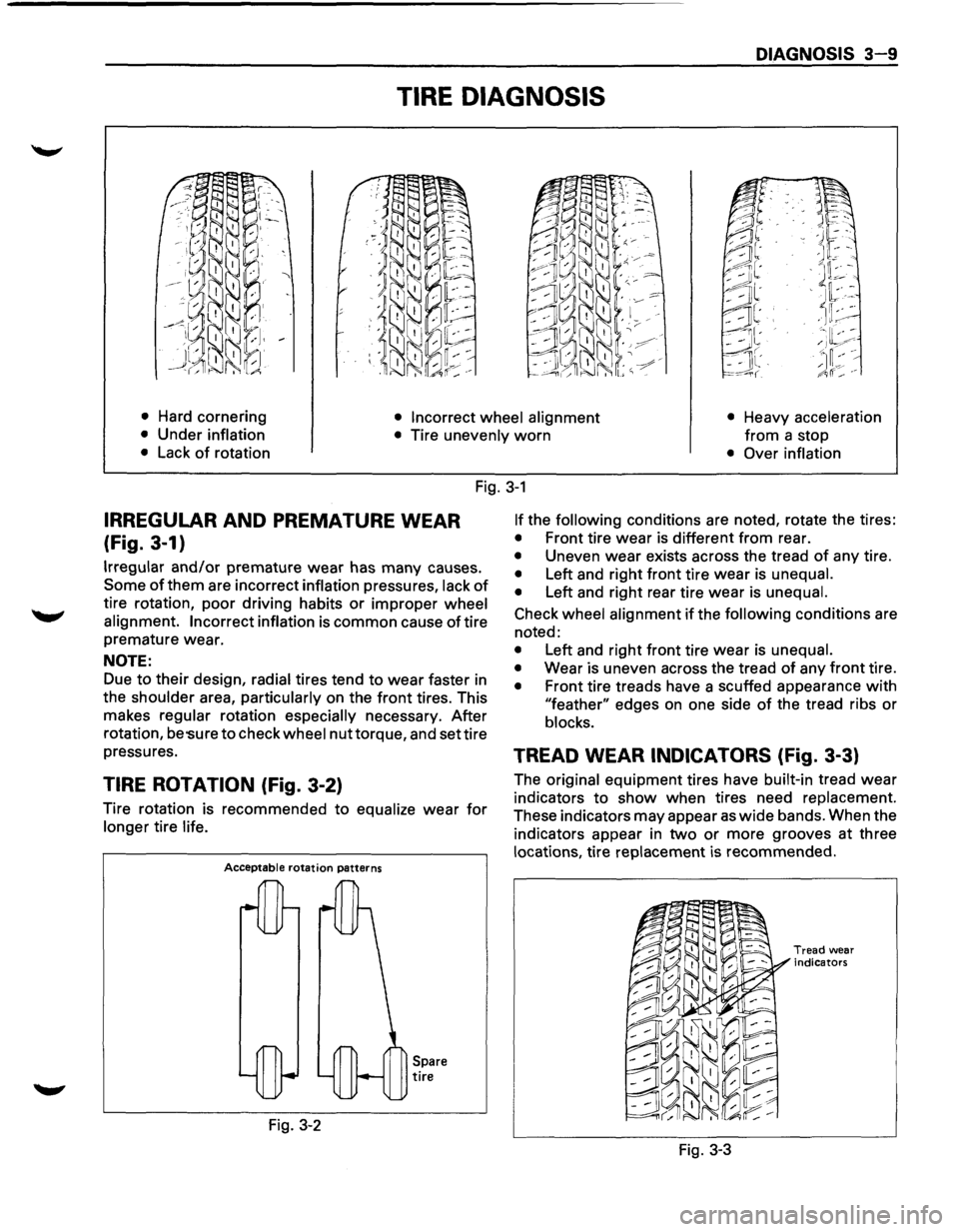
• Hard cornering • Incorrect wheel alignment • Heavy acceleration
from a
stop • Under inflation
• Tire unevenly worn
• Lack of rotation • Over inflation
Fig. 3-1
IRREGULAR AND PREMATURE WEAR
(Fig. 3-1)
Irregular and/or premature wear has many causes.
Some of them are incorrect inflation pressures, lack of
tire rotation, poor driving habits or improper wheel
alignment. Incorrect inflation
is common cause of tire
premature wear.
NOTE:
Due to their design, radial tires tend to wear faster in
the
shoulder area, particularly on the front tires. This
makes
regular rotation especially necessary. After
rotation,
be 'Sure to check wheel nut torque, and set tire
pressures.
TIRE ROTATION (Fig. 3-2)
Tire rotation is recommended to equalize wear for
longer tire life.
Acceptable rotation patterns
Fig. 3-2
Spare tire
If the following conditions are noted, rotate the tires:
• Front tire wear is different from rear.
• Uneven wear exists across the tread of any tire.
• Left and right front tire wear is unequal.
•
Left and right rear tire wear is unequal.
Check wheel alignment if the following conditions are
noted:
• Left and right front tire wear is unequal.
•
Wear is uneven across the tread of any front tire.
• Front tire treads have a scuffed appearance with
"feather" edges on one side of the tread ribs or
blocks.
TREAD WEAR INDICATORS (Fig. 3-3)
The original equipment tires have built-in tread wear
indicators to show when tires need replacement.
These indicators may appear as wide bands. When the
indicators appear in
two or more grooves at three
locations, tire replacement is recommended.
Fig. 3-3
Tread wear
indicators
Page 130 of 1928
3-10 DIAGNOSIS
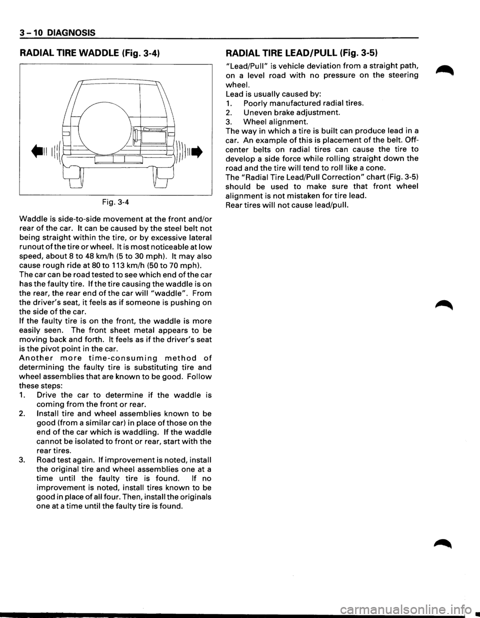
RADIAL TIRE WADDLE (Fig. 3-4)
Fig. 3-4
Waddle is side-to-side
movement at the front and/or
rear of the car. It can be caused by the steel belt not
being straight within the tire, or by excessive lateral
runout of the tire or wheel. It is most noticeable at low
speed, about 8 to 48 km/h (5 to 30 mph). It may also
cause
rough ride at 80 to 113 km/h (50 to 70 mph).
The car can be road tested
to see which end of the car
has
the faulty tire. If the tire causing the waddle is on
the rear, the rear end
of the car will "waddle". From
the
driver's seat, it feels as if someone is pushing on
the side
of the car.
If the faulty tire is on the front, the waddle is more
easily seen. The front sheet metal appears to be
moving back and forth. It feels as if the driver's seat
is
the pivot point in the car.
Another more time-consuming method of
determining the faulty tire is substituting tire and
wheel assemblies
that are known to be good. Follow
these steps:
1. Drive the car to determine if the waddle is
coming from the front or rear.
2. Install tire and wheel assemblies known to be
good (from a similar car) in place ofthose on the
end
of the car which is waddling. If the waddle
cannot be isolated to front or rear, start with the
rear tires.
3. Road test again. If improvement is noted, install
the original tire and wheel assemblies one at a
time until the faulty tire is found. If no
improvement is noted, install tires known to be
good in place of all four. Then, install the originals
one at a
time until the faulty tire is found.
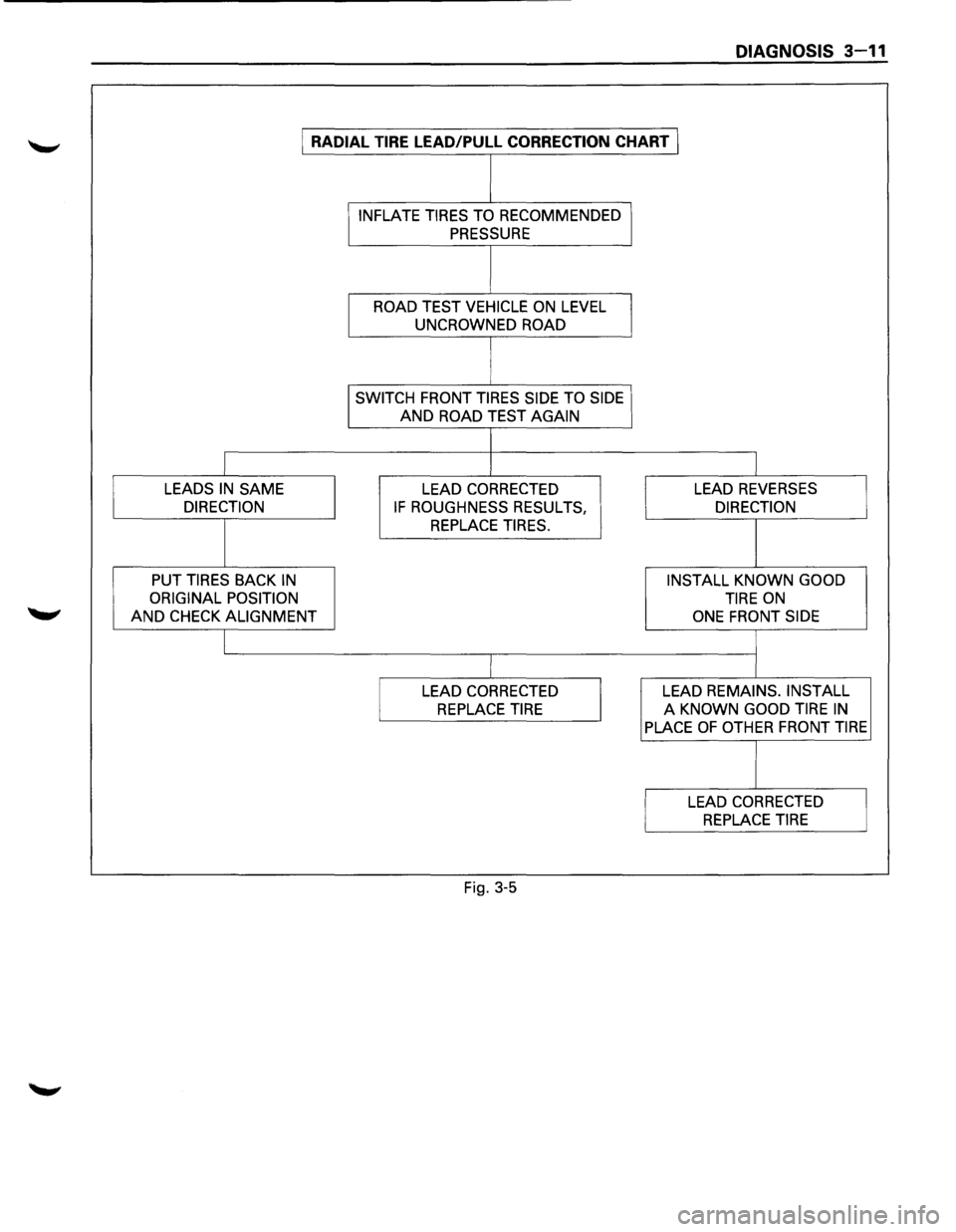
RADIAL TIRE LEAD/PULL (Fig. 3-5)
"Lead/Pull" is vehicle deviation from a straight path,
on a level road
with no pressure on the steering
wheel.
Lead is usually caused by:
1. Poorly manufactured radial tires.
2. Uneven brake adjustment.
3. Wheel alignment.
The
way in which a tire is built can produce lead in a
car.
An example of this is placement of the belt. Off
center belts on radial tires can cause the tire to
develop a side force while rolling straight down the
road and the tire will tend to roll like a cone.
The
"Radial Tire Lead/Pull Correction" chart (Fig. 3-5)
should be used to make sure that front wheel
alignment is not mistaken for tire lead.
Rear
tires will not cause lead/pull.
II
Page 131 of 1928
DIAGNOSIS 3-11
I RADIAL TIRE LEAD/PULL CORRECTION CHART I
I INFLATE TIRES TO RECOMMENDED I
PRESSURE
I
ROAD TEST VEHICLE ON LEVEL
I UNCROWNED ROAD
I SWITCH FRONT TIRES SIDE TO SIDE I
AND ROAD TEST AGAIN
LEADS IN
SAME LEAD CORRECTED LEAD REVERSES
DIRECTION
IF ROUGHNESS RESULTS, DIRECTION
REPLACE TIRES.
PUT TIRES
BACK IN INSTALL KNOWN GOOD
ORIGINAL POSITION
TIRE ON
AND CHECK ALIGNMENT ONE FRONT SIDE
LEAD CORRECTED LEAD REMAINS. INSTALL
REPLACE TIRE
A KNOWN GOOD TIRE IN
PLACE OF OTHER FRONT TIRE
LEAD CORRECTED
REPLACE TIRE
Fig. 3-5
Page 135 of 1928
FRONT END ALIGNMENT 3A-3
ON-VEHICLE SERVICE
INSPECTION
Before making any adjustments affecting caster,
camber or toe-in, the following front end inspection
should be made.
I L•IINSPECT
1. Tires for proper inflation pressure. Refer to
"Wheels and Tires" in section 3E.
2. Front wheel bearings for proper adjustment.
Refer to "Front Wheel Drive" in section 4C.
3. Ball joints, tie rod ends and relay rods. If
excessive looseness is noted, correct before
adjusting. Refer
to "Steering Linkage" in section
3B3.
4. Wheel and tires for run-out. Refer to "Wheels
and Tires" in section 3E.
5. Trim height. If not within specifications, the
correction
must be made before adjusting caster.
6. Steering gear for looseness at the frame.
7. Shock absorbers for leaks or any noticeable
noise.
Refer
to "Front Suspension" in section 3C.
8. Control arms or stabilizer bar attachment for
looseness. Refer to "Front Suspension" in section
3C.
9. Alignment equipment. Follow the manufacturer's
instructions.
10. Level of the vehicle. The vehicle must be on a
level surface.
TRIM HEIGHT ADJUSTMENT
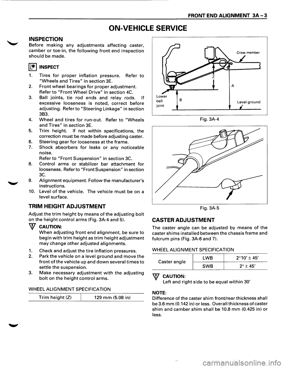
Adjust the trim height by means of the adjusting bolt
on the height control arms (Fig. 3A-4 and 5).
W CAUTION:
When adjusting front end alignment, be sure to
begin with trim height as trim height adjustment
may change other adjusted alignments.
1. Check and adjust the tire inflation pressures.
2. Park the vehicle on a level ground and move the
front of the vehicle up and down several times to
settle the suspension.
3. Make necessary adjustment with the adjusting
bolt on the height control arms.
WHEEL
ALIGNMENT SPECIFICATION
Trim height (Z) 129 mm (5.08 in)
Lower
ball joint
B
Fig. 3A-4
Fig. 3A-5
CASTER ADJUSTMENT
Level ground
The caster angle can be adjusted by means of the
caster shims installed between the chassis frame and
fulcrum pins (Fig. 3A-6 and 7).
WHEEL
ALIGNMENT SPECIFICATION
LWB
Caster angle
SWB
W CAUTION:
Left and right side to be equal within 30'
NOTE:
Difference of the caster shim front/rear thickness shall
be 3.6
mm (0.142 in) or less. Overall thickness of caster
shim and camber shim shall be 10.8 mm (0.425 in) or
less.