cooling ISUZU TROOPER 1995 Service Manual
[x] Cancel search | Manufacturer: ISUZU, Model Year: 1995, Model line: TROOPER, Model: ISUZU TROOPER 1995Pages: 1928
Page 640 of 1928
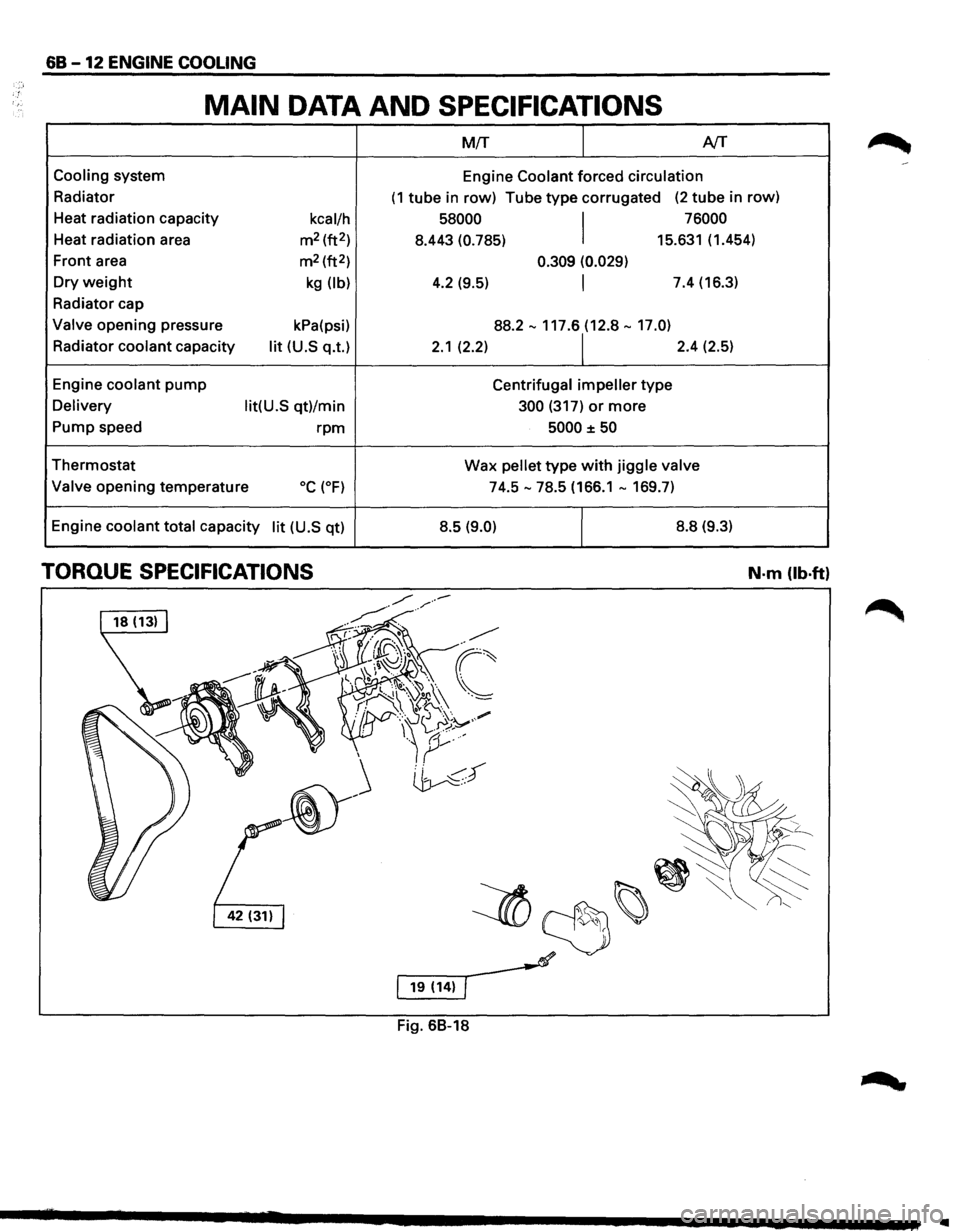
68 -12 ENGINE COOLING
MAIN DATA AND SPECIFICATIONS
M!T I AfT
Cooling system
Engine Coolant forced circulation
Radiator (1 tube in row) Tube type corrugated (2 tube in row)
Heat radiation capacity
kcal/h 58000
I
76000
Heat radiation area m2 (ft2)
8.443 (0.785) 15.631 (1.454)
Front area m2 (ft2) 0.309 (0.029)
Dry weight kg (lb) 4.2 (9.5) I 7.4 (16.3)
Radiator cap
Valve opening pressure kPa(psi) 88.2-117.61(12.8-17.0)
Radiator coolant capacity lit (U.S q.t.) 2.1 (2.2) 2.4 (2.5)
Engine
coolant pump Centrifugal impeller type
Delivery lit(U.S qt)/min 300 (317) or more
Pump speed rpm 5000 ±50
Thermostat Wax pellet type with jiggle valve
Valve
opening temperature oc (oF) 74.5-78.5 (166.1-169.7)
Engine
coolant total capacity lit (U.S qt) 8.5 (9.0) I 8.8
(9.3)
TORQUE SPECIFICATIONS N-m (lb·ft)
Fig. 68-18
..
Page 641 of 1928
ENGINE COOLING 68 -13
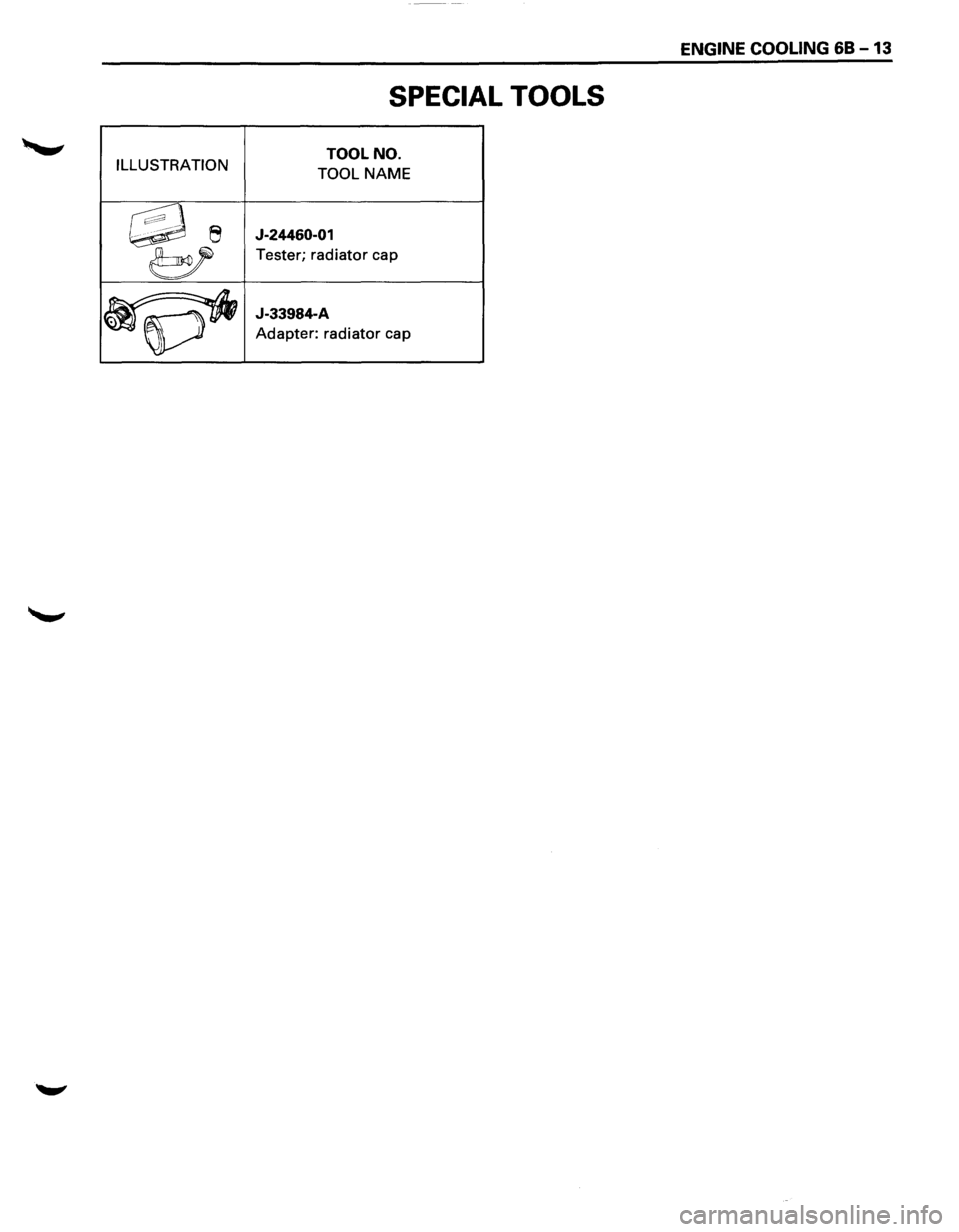
SPECIAL TOOLS
ILLUSTRATION TOOL
NO.
TOOL NAME
~e J-24460-01
e?
Tester; radiator cap
~
J-33984-A
Adapter: radiator cap
Page 707 of 1928
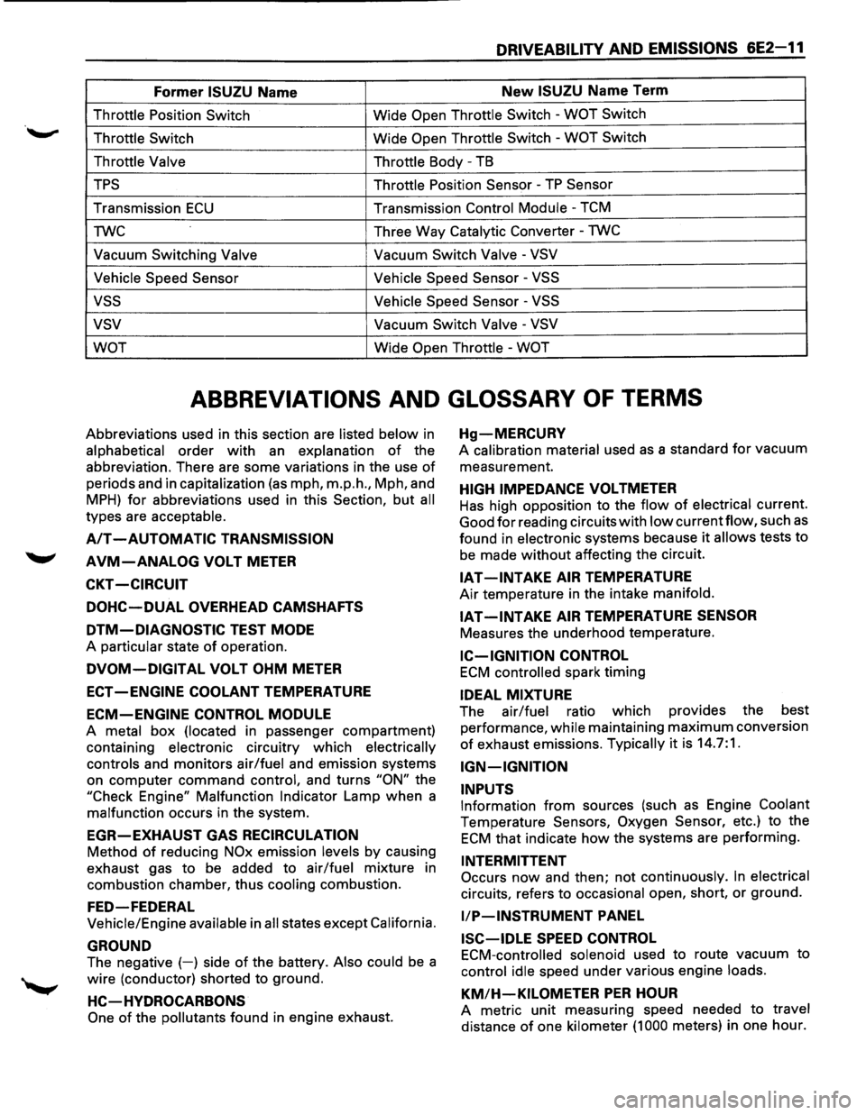
DRIVEABILITY AND EMISSIONS 6E2-11
Former ISUZU Name New ISUZU Name Term
Throttle Position Switch Wide Open Throttle Switch -WOT Switch
Throttle Switch
Wide Open Throttle Switch -WOT Switch
Throttle Valve Throttle
Body -TB
TPS Throttle Position Sensor -TP Sensor
Transmission ECU Transmission Control Module -TCM
TWC Three
Way
Catalytic Converter -TWC
Vacuum Switching Valve Vacuum Switch Valve -VSV
Vehicle Speed Sensor Vehicle
Speed Sensor
-VSS
vss Vehicle Speed Sensor -VSS
vsv Vacuum Switch Valve -VSV
WOT
Wide Open Throttle -WOT
ABBREVIATIONS AND GLOSSARY OF TERMS
Abbreviations used in this section are listed below in
alphabetical order with an explanation of the
abbreviation. There are some variations in the use
of
periods and in capitalization (as mph, m.p.h., Mph, and
MPH) for abbreviations used in this Section, but all
types are acceptable.
A/T -AUTOMATIC TRANSMISSION
AVM-ANALOG VOLT METER
CKT -CIRCUIT
DOHC-DUAL OVERHEAD CAMSHAFTS
DTM-DIAGNOSTIC TEST MODE
A particular state of operation.
DVOM-DIGITAL VOLT OHM METER
ECT -ENGINE COOLANT TEMPERATURE
ECM-ENGINE CONTROL MODULE
A metal box (located in passenger compartment)
containing
electronic circuitry which electrically
controls
and monitors air/fuel and emission systems
on
computer command control, and turns "ON" the
"Check Engine"
Malfunction Indicator Lamp when a
malfunction occurs in the system.
EGR-EXHAUST GAS RECIRCULATION
Method of reducing NOx emission levels by causing
exhaust gas
to be added to air/fuel mixture in
combustion chamber, thus
cooling combustion.
FED-FEDERAL
Vehicle/Engine available in all states except California.
GROUND
The negative (-) side of the battery. Also could be a
wire (conductor) shorted to ground.
HC-HVDROCARBONS
One of the pollutants found in engine exhaust.
Hg-MERCURV
A calibration material used as a standard for vacuum
measurement.
HIGH IMPEDANCE VOLTMETER
Has high opposition to the flow of electrical current.
Good
for reading circuits with low currentflow, such as
found in electronic systems because it allows tests to
be made without affecting the circuit.
IAT -INTAKE AIR TEMPERATURE
Air temperature in the intake manifold.
IAT-INTAKE AIR TEMPERATURE SENSOR
Measures the underhood temperature.
IC-IGNITION CONTROL
ECM controlled spark timing
IDEAL MIXTURE
The air/fuel ratio which provides the best
performance,
while maintaining maximum conversion
of exhaust emissions. Typically it is 14.7:1.
IGN-IGNITION
INPUTS
Information from sources (such as Engine Coolant
Temperature Sensors, Oxygen Sensor, etc.) to the
ECM that indicate how the systems are performing.
INTERMITTENT
Occurs now and then; not continuously. In electrical
circuits, refers to occasional open, short, or ground.
liP-INSTRUMENT PANEL
ISC-IDLE SPEED CONTROL
ECM-controlled solenoid used to route vacuum to
control idle speed under various engine loads.
KM/H-KILOMETER PER HOUR
A metric unit measuring speed needed to travel
distance of one kilometer (1 000 meters) in one hour.
Page 756 of 1928
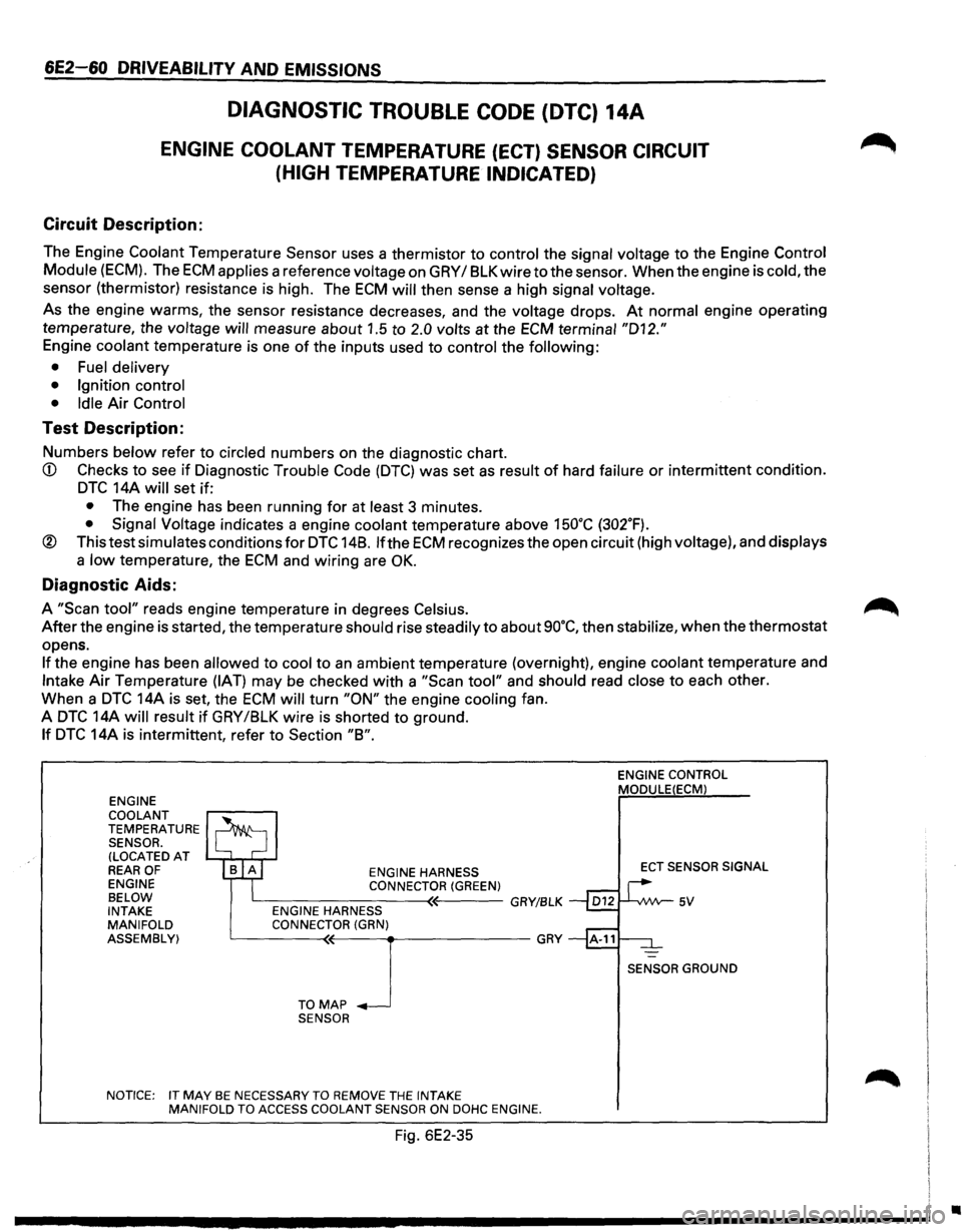
6E2-60 DRIVEABILITY AND EMISSIONS
DIAGNOSTIC TROUBLE CODE (DTC) 14A
ENGINE COOLANT TEMPERATURE (ECT) SENSOR CIRCUIT
(HIGH
TEMPERATURE INDICATED)
Circuit Description:
The Engine Coolant Temperature Sensor uses a thermistor to control the signal voltage to the Engine Control
Module
(ECM). The ECM applies a reference voltage on GRY I 8LK wire to the sensor. When the engine is cold, the
sensor (thermistor) resistance is high. The
ECM will then sense a high signal voltage.
As the engine warms, the sensor resistance decreases, and the voltage drops. At normal engine operating
temperature, the
voltage will measure about 1.5 to 2.0 volts at the ECM terminal "D12."
Engine coolant temperature is one of the inputs used to control the following:
• Fuel delivery
• Ignition control
• Idle
Air Control
Test Description:
Numbers below refer to circled numbers on the diagnostic chart.
CD Checks to see if Diagnostic Trouble Code (DTC) was set as result of hard failure or intermittent condition.
DTC 14A will set if:
• The engine has been running for at least 3 minutes.
• Signal Voltage indicates a engine coolant temperature above 15o•c (302.F).
® This test simulates conditions for DTC 148. lfthe ECM recognizes the open circuit (high voltage), and displays
a low temperature, the ECM and wiring are OK.
Diagnostic Aids:
A "Scan tool" reads engine temperature in degrees Celsius.
After the engine is started, the temperature should rise steadily to about so·c, then stabilize, when the thermostat
opens.
If the engine has been allowed to cool to an ambient temperature (overnight), engine coolant temperature and
Intake Air Temperature (IAT) may be checked with a "Scan tool" and should read close to each other.
When a
DTC 14A is set, the ECM will turn "ON" the engine cooling fan.
A
DTC 14A will result if GRY /8LK wire is shorted to ground.
If DTC 14A is intermittent, refer to Section "8".
ENGINE
COOLANT
TEMPERATURE SENSOR. (LOCATED AT REAR OF ENGINE
BELOW
INTAKE
MANIFOLD
ASSEMBLY) ENGINE
HARNESS CONNECTOR(GREEN) L----------<~---GRY/BLK ENGINE HARNESS
CONNECTOR (GRN)
L__ ___ T_O~M(~A-P-~-~-------GRY
SENSOR
NOTICE: IT
MAY BE NECESSARY TO REMOVE THE INTAKE
MANIFOLD TO ACCESS COOLANT SENSOR ON DOHC ENGINE.
Fig. 6E2-35
ENGINE CONTROL MODULE(ECM)
ECT SENSOR SIGNAL
SENSOR GROUND
•
Page 788 of 1928
6E2-92 DRIVEABILITY AND EMISSIONS
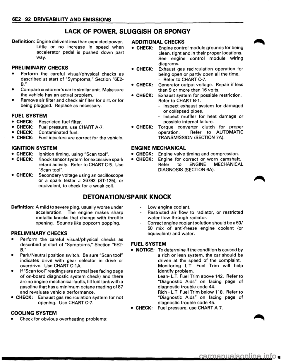
LACK OF POWER, SLUGGISH OR SPONGY
Definition: Engine delivers less than expected power.
Little or no increase in speed when
accelerator
pedal is pushed down part
way.
PRELIMINARY CHECKS
• Perform the careful visual/physical checks as
described at start of "Symptoms," Section "6E2-
B."
•
Compare customer's car to similar unit. Make sure
the
vehicle has an actual problem.
• Remove air filter and check air filter for dirt, or for
being plugged. Replace as necessary.
FUEL SYSTEM
• CHECK: Rescricted fuel filter.
• CHECK: Fuel pressure, use CHART A-7.
• CHECK: Contaminated fuel.
• CHECK: Fuel injectors are correct for the vehicle.
IGNITION SYSTEM
• CHECK: Ignition timing, using "Scan tool".
• CHECK: Knock sensor system for excessive spark
retard activity. Refer to CHART
C-5. Use
"Scan tool".
• CHECK: Secondary voltage using an oscilloscope
or a spark tester J 26792 (ST-125), or
equivalent, to check for a weak coil.
ADDITIONAL CHECKS
• CHECK: Engine control module grounds for being
clean,
tight and in their proper locations.
See engine control module wiring
diagrams.
• CHECK: Exhaust gas recirculation operation for
being open or partly open all the time.
- Refer to CHART
C-7.
• CHECK: Generator output voltage. Repair if less
than 9
or more than 16 volts.
• CHECK: Exhaust system for possible restriction.
Refer
to CHART B-1.
-Inspect exhaust system for damaged
or collapsed pipes.
-
Inspect muffler for heat damage or
possible internal failure.
• CHECK: Torque converter clutch for proper
operation. Refer
to AUTOMATIC
TRANSMISSION
(SECTION 7A).
ENGINE MECHANICAL
• CHECK: Engine valve timing and compression.
• CHECK: Engine for correct or worn camshaft.
Refer
to ENGINE MECHANICAL
DIAGNOSIS
(SECTION 6A).
DETONATION/SPARK KNOCK
Definition: A mild to severe ping, usually worse under
acceleration. The engine makes sharp
metallic knocks that change with throttle
opening.
Sounds like popcorn popping.
PRELIMINARY CHECKS
• Perform the careful visual/physical checks as
Low engine coolant.
Restricted air
flow to radiator, or restricted
water flow through radiator.
Correct engine
coolant solution should be a 50/
50 mix of anti-freeze engine coolant (or
equivalent) and water.
described at start
of "Symptoms," Section "6E2-FUEL SYSTEM
B."
•
Park/Neutral position switch. Be sure "Scan tool"
indicates drive with gear selector in drive or
overdrive. Use
CHART C-1A.
• If "Scan tool" readings are normal (see facing page
of on-board diagnostic system check) and there
are no engine mechanical faults,
fill fuel tank with a
gasoline
that has a minimum octane reading of 87
and revaluate vehicle performance.
• CHECK: Exhaust gas recirculation system for not
opening. Use CHART C-7.
COOLING SYSTEM
• Check for obvious overheating problems:
• NOTICE: To determine if the condition is caused by
a rich
or lean system, the car should be
driven at the speed
of the complaint.
Monitoring
LT. Fuel Trim will help
identify problem.
Lean-
LT. Fuel Trim above 142. Refer to
"Diagnostic Aids" on facing page of
diagnostic trouble code 44.
Rich-LT. Fuel Trim below 118. Refer to
"Diagnostic Aids" on facing page of
diagnostic trouble code 45.
• CHECK: Fuel pressure, use CHART A-7.
..
Page 791 of 1928
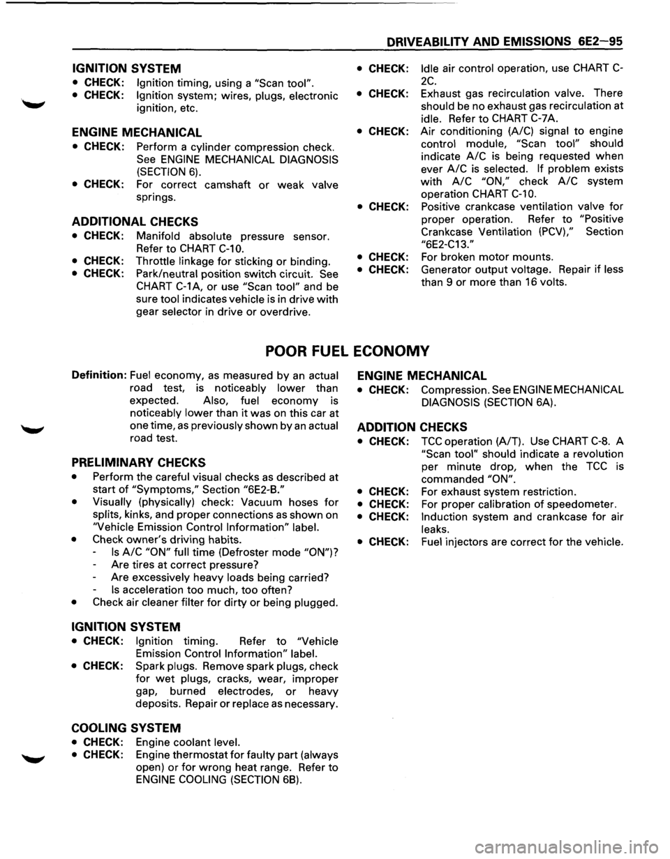
IGNITION SYSTEM
• CHECK: Ignition timing, using a "Scan tool".
• CHECK: Ignition system; wires, plugs, electronic
ignition, etc.
ENGINE MECHANICAL
• CHECK: Perform a cylinder compression check.
See ENGINE MECHANICAL DIAGNOSIS
(SECTION 6).
• CHECK: For correct camshaft or weak valve
springs.
ADDITIONAL CHECKS
• CHECK: Manifold absolute pressure sensor.
Refer to
CHART C-10.
• CHECK: Throttle linkage for sticking or binding.
• CHECK: Park/neutral position switch circuit. See
CHART C-1A,
or use "Scan tool" and be
sure
tool indicates vehicle is in drive with
gear selector in drive or overdrive.
DRIVEABILITY AND EMISSIONS 6E2-95
• CHECK:
• CHECK:
• CHECK:
• CHECK:
• CHECK:
• CHECK:
Idle air control operation, use CHART C-
2C.
Exhaust gas recirculation valve. There
should be no exhaust gas recirculation at
idle. Refer to CHART C-7A.
Air conditioning (A/C) signal to engine
control module, "Scan tool" should
indicate A/C is being requested when
ever
A/C is selected. If problem exists
with A/C "ON," check A/C system
operation
CHART C-10.
Positive crankcase ventilation valve for
proper operation. Refer to "Positive
Crankcase Ventilation (PCV),"
Section
"6E2-C13."
For broken motor mounts.
Generator output
voltage. Repair if less
than 9 or more than 16 volts.
POOR FUEL ECONOMY
Definition: Fuel economy, as measured by an actual
road test, is noticeably lower than
expected.
Also, fuel economy is
noticeably lower than it was on this car at
one time,
as previously shown by an actual
road test.
PRELIMINARY CHECKS
• Perform the careful visual checks as described at
start
of "Symptoms," Section "6E2-B."
• Visually (physically)
check: Vacuum hoses for
splits, kinks, and proper connections as shown on
"Vehicle Emission Control Information" label.
• Check
owner's driving habits.
Is A/C "ON" full time (Defroster mode "ON")?
Are tires at correct pressure?
Are
excessively heavy loads being carried?
Is acceleration too much, too often?
• Check air cleaner filter for dirty or being plugged.
IGNITION SYSTEM
• CHECK: Ignition timing. Refer to "Vehicle
Emission Control Information" label.
• CHECK: Spark plugs. Remove spark plugs, check
for wet plugs, cracks, wear, improper
gap, burned electrodes, or heavy
deposits. Repair or
replace as necessary.
COOLING SYSTEM
• CHECK: Engine coolant level.
• CHECK: Engine thermostat for faulty part (always
open) or for wrong heat range. Refer to
ENGINE COOLING (SECTION 68).
ENGINE MECHANICAL
• CHECK: Compression. See ENGINE MECHANICAL
DIAGNOSIS
(SECTION 6A).
ADDITION CHECKS
• CHECK:
• CHECK:
• CHECK:
• CHECK:
• CHECK:
TCC operation (A/T). Use CHART C-8. A
"Scan tool" should indicate a revolution
per minute drop, when the TCC is
commanded
"ON".
For exhaust system restriction.
For proper
calibration of speedometer.
Induction system and crankcase for air
leaks.
Fuel
injectors are correct for the vehicle.
Page 792 of 1928
6E2-96 DRIVEABILITY AND EMISSIONS
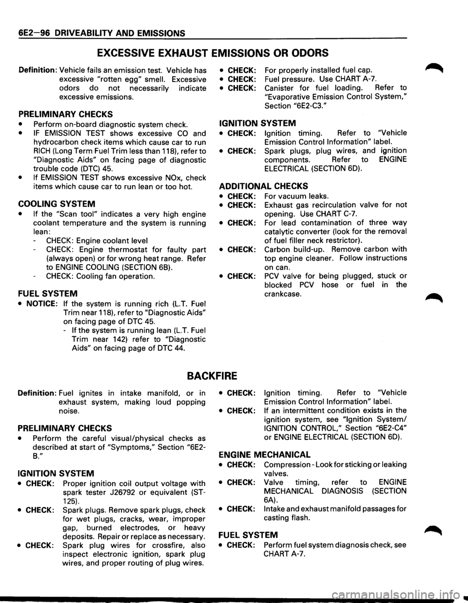
EXCESSIVE EXHAUST EMISSIONS OR ODORS
Definition: Vehicle fails an emission test. Vehicle has
excessive
"rotten egg" smell. Excessive
odors
do not necessarily indicate
excessive emissions.
PRELIMINARY CHECKS
• Perform on-board diagnostic system check.
• IF EMISSION TEST shows excessive CO and
hydrocarbon check items which cause car to run
RICH (Long Term Fuel Trim less than 118), refer to
"Diagnostic Aids" on facing page of diagnostic
trouble code (DTC) 45.
• If EMISSION TEST shows excessive NOx, check
items which cause car
to run lean or too hot.
COOLING SYSTEM
• If the "Scan tool" indicates a very high engine
coolant temperature and the system is running
lean:
CHECK: Engine coolant level
CHECK: Engine thermostat for faulty part
(always open) or for wrong heat range. Refer
to
ENGINE COOLING (SECTION 68).
CHECK: Cooling fan operation.
FUEL SYSTEM
• NOTICE: If the system is running rich (L.T. Fuel
Trim near 118), refer to "Diagnostic Aids"
on facing page
of DTC 45.
-
If the system is running lean (L.T. Fuel
Trim near 142) refer to "Diagnostic
Aids" on facing page of DTC 44.
• CHECK: For properly installed fuel cap.
• CHECK: Fuel pressure. Use CHART A-7.
• CHECK: Canister for fuel loading. Refer to
"Evaporative Emission Control System,"
Section
"6E2-C3."
IGNITION SYSTEM
• CHECK: Ignition timing. Refer to "Vehicle
Emission Control Information" label.
• CHECK: Spark plugs, plug wires, and ignition
components. Refer to
ENGINE
ELECTRICAL (SECTION 6D).
ADDITIONAL CHECKS
• CHECK: For vacuum leaks.
• CHECK: Exhaust gas recirculation valve for not
opening. Use CHART C-7.
• CHECK: For lead contamination of three way
catalytic converter (look for the removal
of fuel filler neck restrictor).
• CHECK: Carbon build-up. Remove carbon with
top engine cleaner. Follow instructions
on can.
• CHECK: PCV valve for being plugged, stuck or
blocked PCV hose or fuel in the
crankcase.
BACKFIRE
Definition: Fuel ignites in intake manifold, or in
exhaust system, making
loud popping
noise.
PRELIMINARY CHECKS
• Perform the careful visual/physical checks as
described at start of "Symptoms," Section "6E2-
B."
IGNITION SYSTEM
• CHECK: Proper ignition coil output voltage with
spark tester J26792 or equivalent (ST-
125).
• CHECK: Spark plugs. Remove spark plugs, check
for
wet plugs, cracks, wear, improper
gap, burned
electrodes, or heavy
deposits. Repair
or replace as necessary.
• CHECK: Spark plug wires for crossfire, also
inspect electronic ignition, spark plug
wires, and proper routing of plug wires.
• CHECK: Ignition timing. Refer to "Vehicle
Emission Control Information" label.
• CHECK: If an intermittent condition exists in the
ignition system, see
"Ignition System/
IGNITION CONTROL," Section "6E2-C4"
or ENGINE ELECTRICAL (SECTION 6D).
ENGINE MECHANICAL
• CHECK: Compression- Look for sticking or leaking
valves.
• CHECK: Valve timing, refer to ENGINE
MECHANICAL DIAGNOSIS (SECTION
6A).
• CHECK: Intake and exhaust manifold passages for
casting
flash.
FUEL SYSTEM
• CHECK: Perform fuel system diagnosis check, see
CHART A-7.
Page 857 of 1928
DRIVEABILITV AND EMISSIONS 6E2-161
SECTION C-1 0
AIR CONDITIONING (A/C) COMPRESSOR CLUTCH CONTROL
SYSTEM
CONTENTS
General Description ..................... 6E2-161 On-Vehicle Service ...................... 6E2-161
Operation ........................... 6E2-161 Chart C-10 Air Conditioning (A/C) System
Diagnosis ............................. 6E2-161 Functional Check ...................... 6E2-162
GENERAL DESCRIPTION
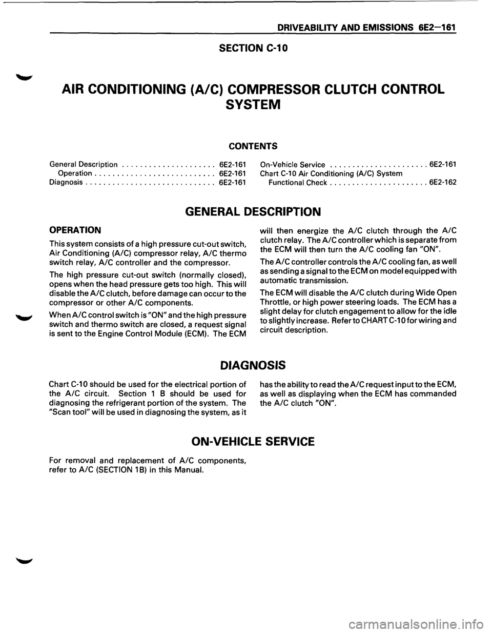
OPERATION
This system consists of a high pressure cut-out switch,
Air Conditioning (A/C) compressor
relay, A/C thermo
switch relay, A/C controller and the compressor.
The high pressure cut-out switch
(normally closed),
opens when the head pressure gets too high. This will
disable
the A/C clutch, before damage can occur to the
compressor or other
A/C components.
When
A/C control switch is "ON" and the high pressure
switch and thermo switch are
closed, a request signal
is sent to the Engine Control Module (ECM). The ECM
will then energize the A/C clutch through the A/C
clutch relay. The A/C controller which is separate from
the ECM will then turn the A/C cooling fan "ON".
The A/C controller controls the A/C cooling fan, as well
as sending a signal to the ECM on model equipped with
automatic transmission.
The
ECM will disable the A/C clutch during Wide Open
Throttle,
or high power steering loads. The ECM has a
slight delay for clutch engagement to allow for the idle
to slightly increase. Refer to CHART C-1 0 for wiring and
circuit description.
DIAGNOSIS
Chart C-10 should be used for the electrical portion of
the A/C circuit. Section 1 B should be used for
diagnosing the refrigerant portion of the system. The
"Scan tool" will be used in diagnosing the system, as it
has the ability to read the A/C request inputto the ECM,
as well as displaying when the ECM has commanded
the
A/C clutch "ON".
ON-VEHICLE SERVICE
For removal and replacement of A/C components,
refer to
A/C (SECTION 1 B) in this Manual.
Page 883 of 1928

AUTOMATIC TRANSMISSION (4L30-E) 7 A-11
FUNCTIONS OF INPUT /OUTPUT COMPONENTS
Components Function
Speed sensor
Senses rotation
of output shaft and feeds the data to Transmission
(fixed
to transmission (T/M)) Control Module (TCM)
Throttle Senses the extent of throttle valve opening and the speed of the throttle
position sensor (TPS) valve lever motion to open the valve and feeds the data to TCM (fed to
(fixed to engine)
Engine Control Module (ECM) also)
I
Brake Switch (SW) Senses whether the driver has pressed the brake pedal or not and feeds
N (fixed
to brake pedal) the
information to TCM
p Kick-down SW (fixed to Senses whether the driver has pushed the accelerator pedal fully or not
u accelerator pedal) and feeds the information to TCM
T Mode
SW (fixed to T/M) Senses the select lever position and feeds the information to TCM
s Power drive SW Senses whether the driver has selected the power mode and feeds the
I (fixed to front console) information to TCM
G T/M
oil temp. sensor
Senses the T/M oil temperature and feeds the data to TCM
N Engine
coolant Senses the engine cooling water temperature and feeds the data to TCM
A temperature
SW (feeds the signal from ECM)
L
Engine speed
signal Feeds the signals monitoring engine speed to TCM from Ignition Control
Module
(fed to ECM also)
Air conditioning Senses whether the air conditioner has been switched on or not and
information feeds the information
to TCM
On-board diagnostic
input By monitoring the Ground (GND), the location of failure is shown on the
T/M
monitor lamp ("CHECK TRANS") by flashing the diagnostic trouble
code
Winter switch
Senses whether the driver has selected the winter mode, and feeds the
(fixed
to front console) information to TCM
Cruise
controller Downshift takes place when Overdrive OFF signal is received from auto
(Overdrive
OFF signal) cruise control unit
Shift
solenoid Selects shift point and gear position suited to the vehicle running con-s 1-2/3-4, 2-3
dition on the basis of TCM output 0 Band apply solenoid
Controls oil flow suited to the vehicle running condition on the basis of L
E TCM output
0 N
Torque
Converter Controls clutch engagement/disengagement suited to the vehicle
u 0 Clutch solenoid running condition on the basis of TCM output
T I Force motor Adjusts the oil pump delivery pressure to line pressure suited to the p D
(Pressure regulator vehicle running condition on the basis of TCM output u valve) T
Power drive mode lamp
Informs the driver whether the vehicle is in power mode or not
s Winter drive mode lamp Informs the driver whether the vehicle is in winter mode or not
I T/M monitor lamp Informs the driver of failure in the system. It also displays the self diagnosis
G
("CHECK TRANS") code.
N Data Link Connector
(DLC) When connected with TECH 1 or tester, can communicate the data for A
L function
check, etc. (fed to ECM also). When TECH 1 is not connected, can
communicate the
signal for torque management with ECM.
Self-diagnosis connector
When short-circuited with the bipolar connector, the T/M monitor lamp
displays
a failure by code.
ATF warning
lamp Lights when ATF oil temperature rises.
ABS signal When the select lever is at "Reverse" or "L" range, sends a signal to the
ABS controller as one of the ABS control conditions.