drain bolt ISUZU TROOPER 1995 User Guide
[x] Cancel search | Manufacturer: ISUZU, Model Year: 1995, Model line: TROOPER, Model: ISUZU TROOPER 1995Pages: 1928
Page 620 of 1928
'.n
6A1-62 ENGINE (V6 3.2L DOHC AND SOHC)
E) REMOVAL
Preparation: • Disconnect battery ground cable.
• Remove engine hood.
In order to return the hood to the
original position exactly, make
alignment on the hood and hinges
before
removal.
•
Drain radiator coolant.
1. Accelerator cable
• Disconnect from throttle valve and common
chamber.
2. Ventilation hose
3.
Air hose
4. Air cleaner assembly
5. Canister vacuum hose
6. Vacuum booster hose
7. Engine harness connectors
• Disconnect three connectors on canister side.
8. Battery ground cables
• Disconnect two black and white connector
clips
from the power steering pump bracket.
9. Ground cables
• Disconnect two terminals connected to the
battery support and the
front right frame.
1 0. Bonding cable connector
• Disconnect connector on the left side dash
panel.
11. Bonding cable terminal
• Disconnect terminal on the back of left bank.
12. Starter harness connector
• Disconnect from starter.
13. Radiator
• Disconnect upper and lower hoses from the
engine.
• Disconnect coolant reserve tank hose from
radiator.
• Disconnect ATF hose from the pipe. (A/T)
• Remove radiator lower hose clip from the hose
bracket.
• Remove radiator lower fan shroud.
• Remove radiator.
14. Power steering pump drive belt
15. Power steering pump
• Remove two bolts on the bracket, and place the
pump along with piping on the body side.
16. Air Conditioning compressor drive belt
17. Air Conditioning compressor
• Remove fixing bolts and shift aside the
compressor
with piping attached.
18. Heater hoses
• Disconnect two hoses from the engine.
19. ATF pipes
• Disconnect two pipes from right side engine
mount.
20. Transmission assembly
• See "Transmission Removal and Installation"
in Section 7.
21. Left side engine mount
• Support the engine.
• Remove two fixing bolts from engine mount on
chassis side.
22. Right side engine mount
• Remove two fixing bolts from engine mount on
chassis side.
23. Engine assembly
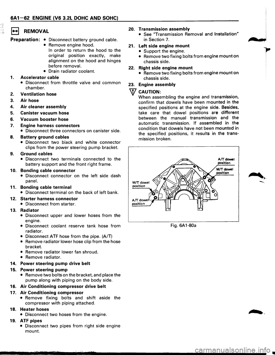
w CAUTION:
When assembling the engine and transmission,
confirm
that dowels have been mounted in the
specified positions at the engine side. Besides,
take care
that dowel positions are different
between the manual transmission and the
automatic transmission.
If assembled in the
condition that dowels have not been mounted in
the specified positions,
it results in the trans
mission broken.
M/Tdowel position
AIT doweiY~--r..ri~-' position
Fig. 6A1-80a
n t b,
•
Page 633 of 1928
EJ REMOVAL
Preparation
• Disconnect battery ground cable.
•
Drain coolant.
•
Radiator hose (on inlet pipe side)
1. Timing belt
• (Refer to Timing belt removal steps in Section
6A1, 6A2)
2. Idle pulley
3. Water pump assembly
4. Gasket
~ INSPECTION
Make necessary repair and parts replacement if ex
treme wear or damage is found during inspection.
Should any of the following problems occur, the
entire water pump assembly must be replaced.
•
Cracks in the Engine Coolant (EC) pump body
• EC leakage from the seal unit
• Play or abnormal noise in the bearing
• Cracks or corrosion in the impeller
8 INSTALLATION
4. Gasket
• Clean the mating surface of packing before
installation.
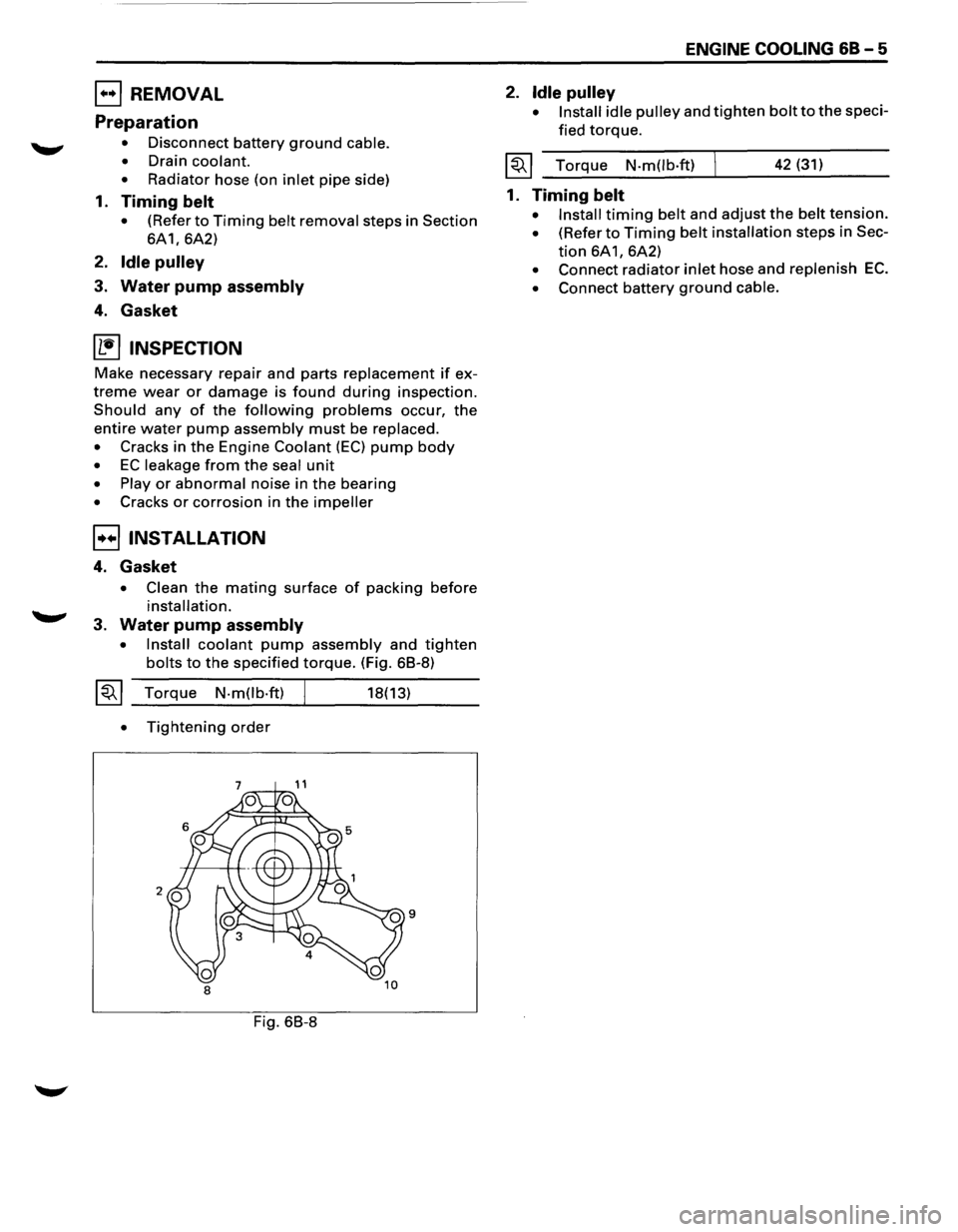
3. Water pump assembly
• Install coolant pump assembly and tighten
bolts to the specified torque. (Fig. 68-8)
~~~ Torque N-m(lb-ft)
•
Tightening order
Fig. 68-8
18(13)
ENGINE COOLING 68-5
2. Idle pulley
• Install idle pulley and tighten bolt to the speci
fied
torque.
~~~ Torque N-m(lb·ft) 42 (31)
1. Timing belt
• Install timing belt and adjust the belt tension.
• (Refer to Timing belt installation steps in Sec
tion 6A1, 6A2)
• Connect radiator inlet hose and replenish EC.
• Connect battery ground cable.
Page 635 of 1928
B INSTALLATION
3. Thermostat
• Install thermostat into the thermostat hous
ing, making sure
that the jiggle valve in up
position.
2. Packing
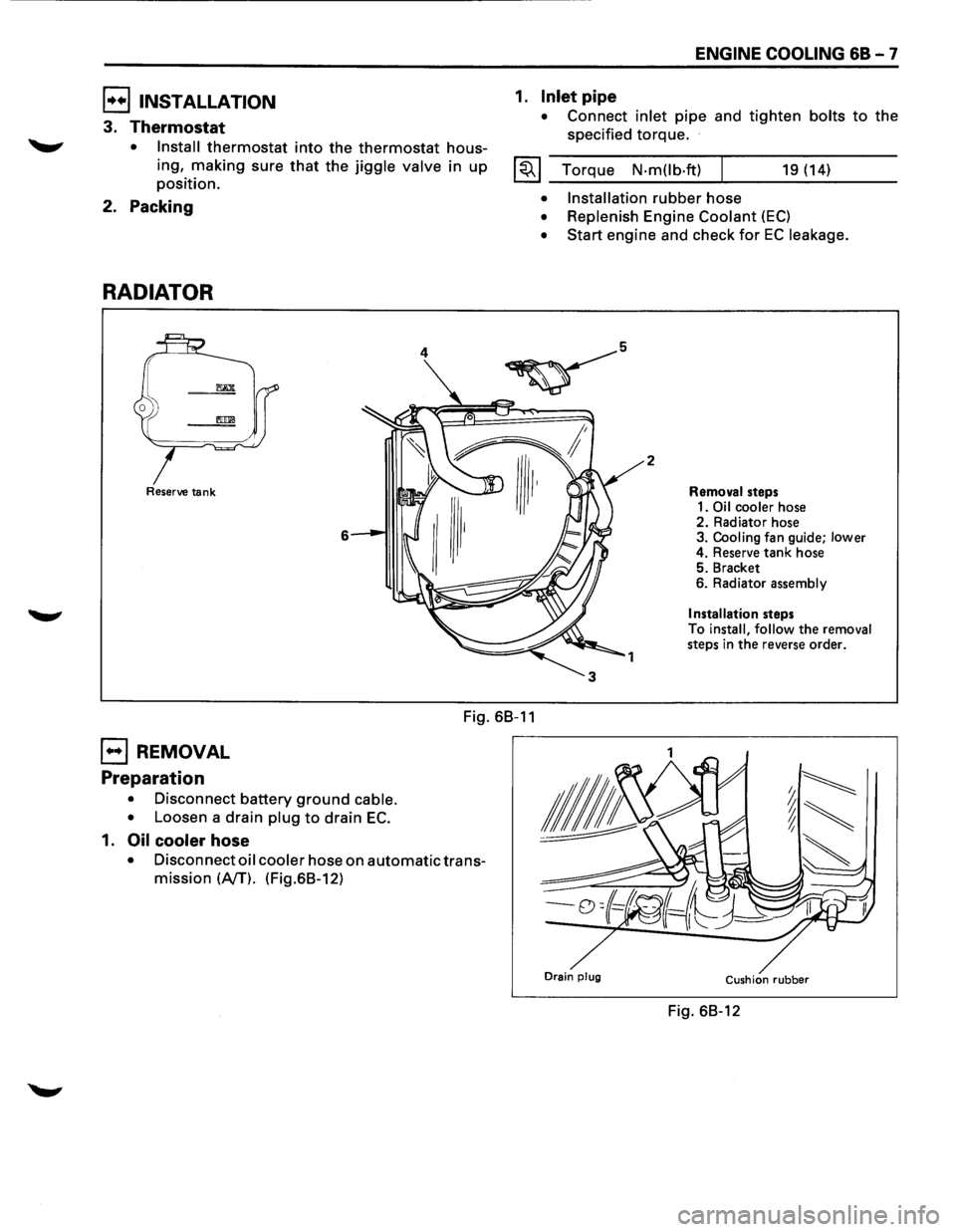
RADIATOR
Reserve tank
6
ENGINE COOLING 68-7
1. Inlet pipe
• Connect inlet pipe and tighten bolts to the
specified torque.
I~~ Torque N·mOb·ft) 19 (14)
• Installation rubber hose
• Replenish Engine Coolant (EC)
• Start engine and check for EC leakage.
2
Removal steps
1.
Oil cooler hose 2. Radiator hose
3. Cooling fan guide; lower
4. Reserve tank hose
5. Bracket
6. Radiator assembly
Installation steps
To install, follow the removal
steps in the reverse order.
Fig. 68-11
EJ REMOVAL
Preparation
• Disconnect battery ground cable.
•
Loosen a drain plug to drain EC.
1. Oil cooler hose
• Disconnect oil cooler hose on automatic trans
mission
(NT). (Fig.68-12)
Drain plug Cushion rubber
Fig. 68-12
Page 645 of 1928
ENGINE FUEL 6C - 3
ON-VEHICLE SERVICE
When repair to the fuel system has been com
pleted, start engine and check the fuel system for
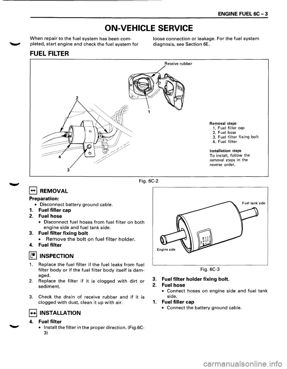
FUEL FILTER
2
3
loose connection or leakage. For the fuel system
diagnosis, see Section 6E.
Receive rubber
Rer:noval steps 1. Fuel filler cap 2. Fuel hose
3. Fuel filter fixing bolt
4. Fuel filter
Installation steps To install, follow the removal steps in the
reverse order.
Fig. 6C-2
EJ REMOVAL
Preparation:
• Disconnect battery ground cable.
1. Fuel filler cap
2. Fuel hose
• Disconnect fuel hoses from fuel filter on both
engine side and fuel tank side.
3. Fuel filter fixing bolt
•
Remove the bolt on fuel filter holder.
4. Fuel filter
(1!] INSPECTION
1. Replace the fuel filter if the fuel leaks from fuel
filter body or if the fuel filter body itself is dam
aged.
2. Replace the filter if it is clogged with dirt or
sediment.
3. Check the drain of receive rubber and if it is
clogged with dust, clean it up with air.
B INSTALLATION
4. Fuel filter
.......,. • Install the filter in the proper direction. (Fig.6C-
3)
Fig. 6C-3
3. Fuel filter holder fixing bolt.
2. Fuel hose
• Connect hoses on engine side and fuel tank
side.
1. Fuel filler cap
• Connect the battery ground cable.
Page 648 of 1928
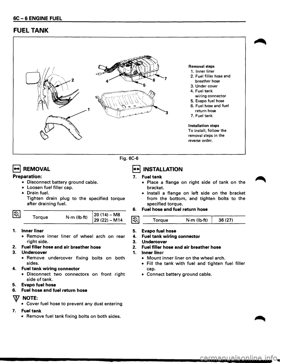
6C-6 ENGINE FUEL
FUEL TANK
7
1 3
Removal steps
1.1nnerliner
2. Fuel filler hose and
breather hose
3. Under cover
4.
Fuel tank
wiring connector
5. Evapo fuel hose
6.
Fuel hose and fuel
return hose
7. Fuel tank
Installation steps
To
install, follow the
removal steps in the
reverse order.
Fig. 6C-6
B REMOVAL
Preparation:
• Disconnect battery ground cable.
•
Loosen fuel filler cap.
• Drain fuel.
Tighten drain plug to the specified torque
after draining fuel.
Torque
1. Inner liner
N·m (lb·ft) 20 (14)-M8
29 (22)-M14
• Remove
inner liner of wheel arch on rear
right side.
2.
Fuel filler hose and air breather hose
3.
Undercover
• Remove undercover fixing bolts on both
sides.
4. Fuel tank wiring connector
• Disconnect two connectors on front right
side of tank.
5. Evapo fuel hose
6. Fuel hose and fuel return hose
W NOTE:
• Cover fuel hose to prevent any dust entering
7. Fuel tank
• Remove fuel tank fixing bolts on both sides.
I!!] INSTALLATION
7.
6.
Fuel tank
• Place a flange on right side of tank on the
bracket.
• Install a flange on left side on the bracket
from the bottom, and tighten bolts to the
specified torque.
Fuel hose and fuel return hose
Torque N·m Ob·ft) 36 (27)
5. Evapo fuel hose
4. Fuel tank wiring connector
3. Undercover
2. Fuel filler hose and air breather hose
1. Inner liner
• Mount inner liner on the wheel arch.
• Fill the tank with fuel and tighten fuel filler
cap.
• Connect battery ground cable.
Page 821 of 1928
Names of component parts can be found on the
numbered
list on the disassembled view (Fig. 6E2-78).
Fig. 6E2-78
Throttle Body (TB)
5
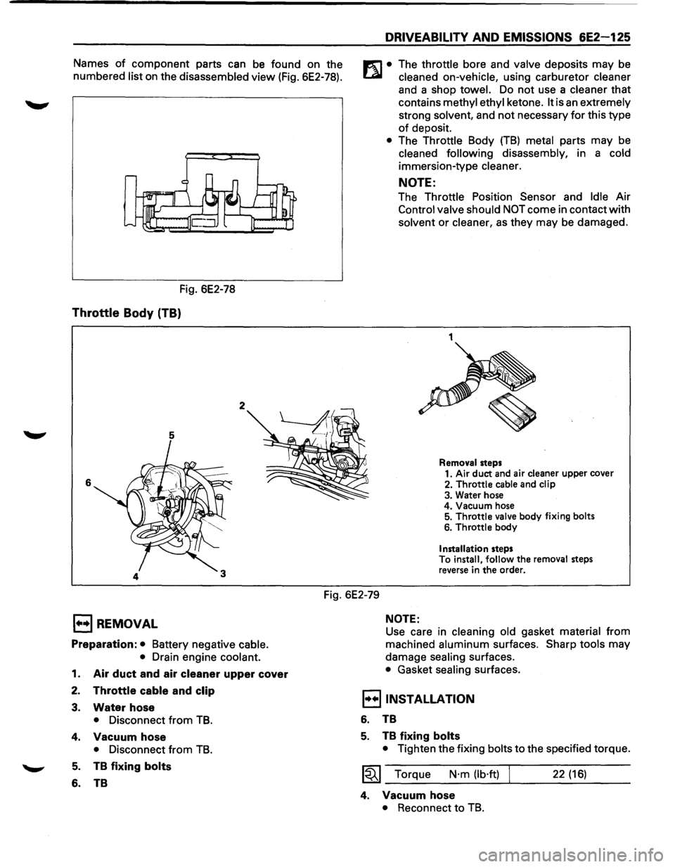
6
2
DRIVEABILITY AND EMISSIONS 6E2-125
m • The throttle bore and valve deposits may be
t..a.l cleaned on-vehicle, using carburetor cleaner
and a shop towel. Do not use a cleaner that
contains
methyl ethyl ketone. It is an extremely
strong solvent, and
not necessary for this type
of deposit.
• The Throttle Body (TB) metal parts may be
cleaned following disassembly, in a cold
immersion-type cleaner.
NOTE:
The Throttle Position Sensor and Idle Air
Control
valve should NOT come in contact with
solvent or
cleaner, as they may be damaged.
1
Removal steps
1. Air duct and air cleaner upper cover
2.
Throttle cable and clip
3. Water hose
4. Vacuum hose
5.
Throttle valve body fixing bolts
6. Throttle body
Installation steps
To install, follow the removal steps
reverse in
the order.
Fig. 6E2-79
1••1 REMOVAL
Preparation: • Battery negative cable.
•
Drain engine coolant.
1. Air duct and air cleaner upper cover
2. Throttle cable and clip
3. Water hose
• Disconnect from TB.
4. Vacuum hose
• Disconnect from TB.
5. TB fixing bolts
6. TB
NOTE:
Use care in cleaning old gasket material from
machined
aluminum surfaces. Sharp tools may
damage
sealing surfaces.
• Gasket sealing surfaces.
I••IINSTALLATION
6. TB
5. TB fixing bolts
• Tighten the fixing bolts to the specified torque.
~~~ Torque N·m (lb·ft) 22 (16)
4. Vacuum hose
• Reconnect to TB.
Page 912 of 1928
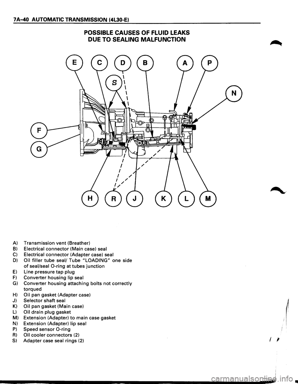
7 A-40 AUTOMATIC TRANSMISSION (4L30-E)
POSSIBLE CAUSES OF FLUID LEAKS
DUE
TO SEALING MALFUNCTION
A) Transmission vent (Breather)
B) Electrical connector (Main case) seal
C) Electrical connector (Adapter case) seal
D) Oil filler tube seal/ Tube "LOADING" one side
of seal/seal 0-ring at tubes junction
E) Line pressure tap plug
F) Converter housing lip seal
G) Converter housing attaching bolts not correctly
torqued
H) Oil pan gasket (Adapter case)
J) Selector shaft seal
Kl
Oil pan gasket (Main case)
L) Oil drain plug gasket
M) Extension (Adapter)
to main case gasket
Nl Extension (Adapter) lip seal
P) Speed sensor 0-ring
R) Oil cooler connectors (2)
S) Adapter case seal rings (2)
~·
I '
..
Page 1027 of 1928
... ......,.
AUTOMATIC TRANSMISSION (4L30-E) 7A-155
ON-VEHICLE SERVICE
CHECKING TRANSMISSION FLUID
LEVEL
1. Park the vehicle on level ground.
2. Apply the parking brake.
3. Place the automatic transmission in "Park" and
start the engine.
Allow the engine to idle for
two minutes.
4. With the brakes applied, move the shifter lever
through all the gear ranges, ending in "Park".
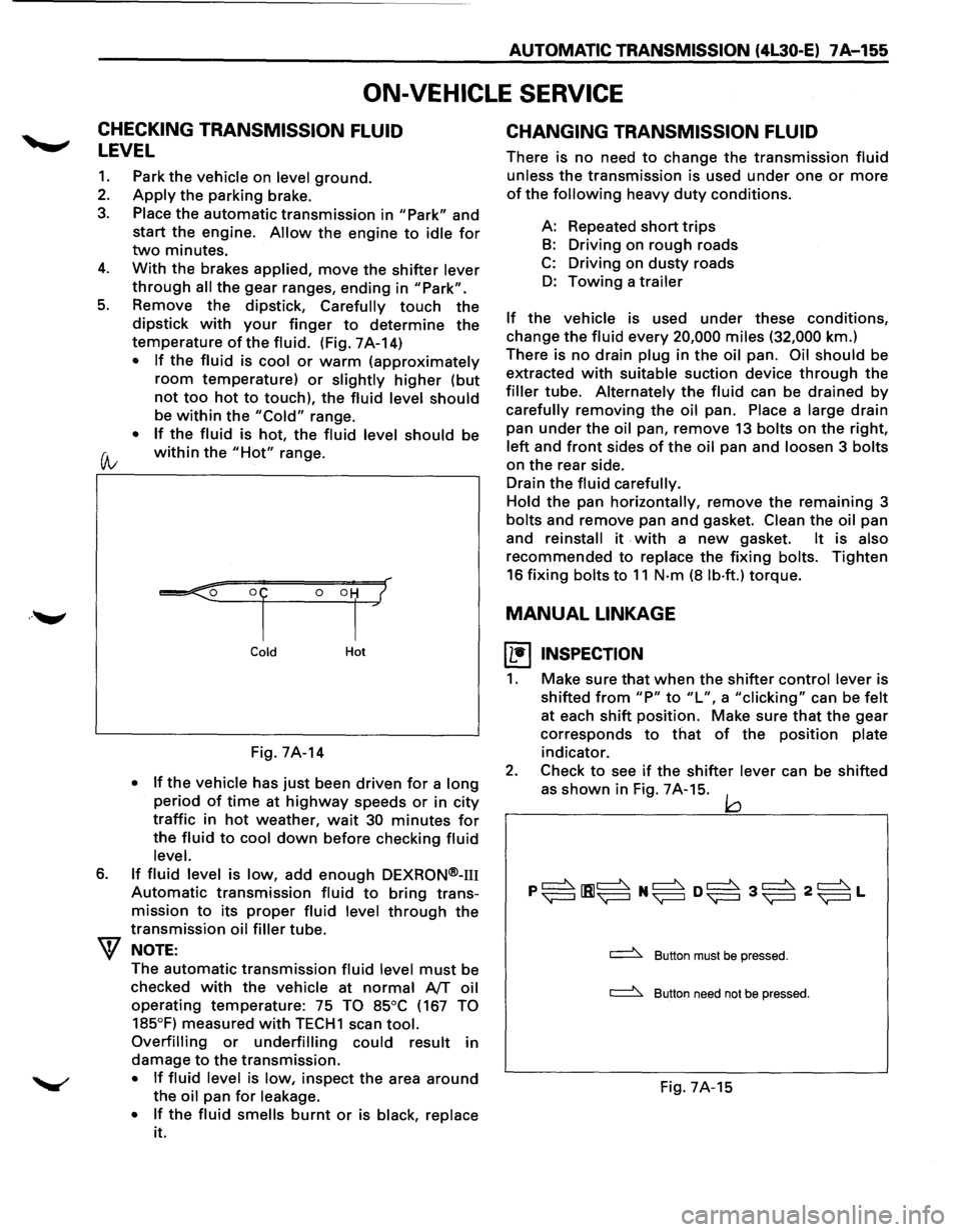
5. Remove the dipstick, Carefully touch the
dipstick with your finger to determine the
temperature of the fluid. (Fig. 7A-14)
• If the fluid is cool or warm (approximately
room temperature) or slightly higher (but
not too hot to touch), the fluid level should
be within the "Cold" range.
• If the fluid is hot, the fluid level should be
(A; within the "Hot" range.
6.
Cold Hot
Fig. 7A-14
• If the vehicle has just been driven for a long
period of time at highway speeds or in city
traffic in hot weather, wait 30 minutes for
the fluid to cool down before checking fluid
level.
If fluid level is low, add enough DEXRON®-m
Automatic transmission fluid to bring trans
mission
to its proper fluid level through the
transmission oil filler tube.
NOTE:
The automatic transmission fluid level must be
checked
with the vehicle at normal AfT oil
operating temperature: 75 TO 85°C (167 TO
185°F)
measured with TECH1 scan tool.
Overfilling or underfilling could result in
damage
to the transmission.
• If fluid level is low, inspect the area around
the oil pan for leakage.
•
If the fluid smells burnt or is black, replace
it.
CHANGING TRANSMISSION FLUID
There is no need to change the transmission fluid
unless the transmission is used under one or more
of the following heavy duty conditions.
A: Repeated
short trips
B: Driving on rough roads
C: Driving on dusty roads
D: Towing a trailer
If the vehicle is used under these conditions,
change the fluid every 20,000 miles (32,000 km.)
There is
no drain plug in the oil pan. Oil should be
extracted
with suitable suction device through the
filler tube. Alternately the fluid can be drained by
carefully removing the oil pan. Place a large drain
pan
under the oil pan, remove 13 bolts on the right,
left and front sides of the oil pan and loosen 3 bolts
on the rear side.
Drain
the fluid carefully.
Hold
the pan horizontally, remove the remaining 3
bolts and remove pan and gasket. Clean the oil pan
and
reinstall it . with a new gasket. It is also
recommended to replace the fixing bolts. Tighten
16 fixing bolts to 11 N·m (8 lb·ft.) torque.
MANUAL LINKAGE
~ INSPECTION
1. Make sure that when the shifter control lever is
shifted
from "P" to "L", a "clicking" can be felt
at each shift position. Make sure that the gear
corresponds
to that of the position plate
indicator.
2. Check to see if the shifter lever can be shifted
as
shown in Fig. 7A-15. jQ
~ Button must be pressed.
~ Button need not be pressed.
Fig. 7A-15
Page 1038 of 1928
7A-166 AUTOMATIC TRANSMISSION (4l30-E)
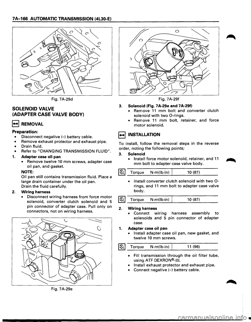
Fig. 7A-29d
SOLENOID VALVE
(ADAPTER CASE VALVE BODY)
l++l REMOVAL
Preparation:
• Disconnect negative(-) battery cable.
• Remove exhaust protector and exhaust pipe.
• Drain fluid.
• Refer to "CHANGING TRANSMISSION FLUID".
1. Adapter case oil pan
• Remove twelve 10 mm screws, adapter case
oil pan, and gasket.
NOTE:
Oil pan still contains transmission fluid. Place a
large
drain container under the oil pan.
Drain
the fluid carefully.
2. Wiring harness
• Disconnect wiring harness from force motor
solenoid, converter clutch solenoid and 5
pin
connector of adapter case. Pull only on
connectors,
not on wiring harness.
Fig. 7A-29e Fig.
7A-29f
3. Solenoid (fig. 7 A-29e and 7 A-29f)
• Remove 11 mm bolt and converter clutch
solenoid
with two 0-rings.
• Remove 11 mm bolt, retainer, and force
motor solenoid.
1••1 INSTALLATION
To install, follow the removal steps in the reverse
order,
noting the following points;
3. Solenoid
• Install force motor solenoid, retainer, and 11
mm bolt to adapter case valve body.
~~~ Torque N-m(lb-in) I 10 (87)
• Install converter clutch solenoid with two 0-
rings, and 11 mm bolt to adapter case valve
body.
~~~ Torque N-mOb·in) 10 (87)
2. Wiring harness
• Connect w1nng harness assembly to
solenoids and 5 pin connector of adapter
case.
1. Adapter case oil pan
• Install adapter case oil pan, new gasket, and
twelve 10 mm screws.
~~~ Torque~ N·mOb·in) I 11 (96)
• Fill transmission through the oil filter tube,
usin~1 ATF DEXRON®-111.
• Install exhaust protector and exhaust pipe.
• Connect negative (-) battery cable.
•
Page 1103 of 1928
1•!,.1 DISASSEMBLY
Preparation:
• Clean the exterior of the unit with solvent.
•
Remove the drain plug from the transmission
case and transfer case and drain the
lubricant.
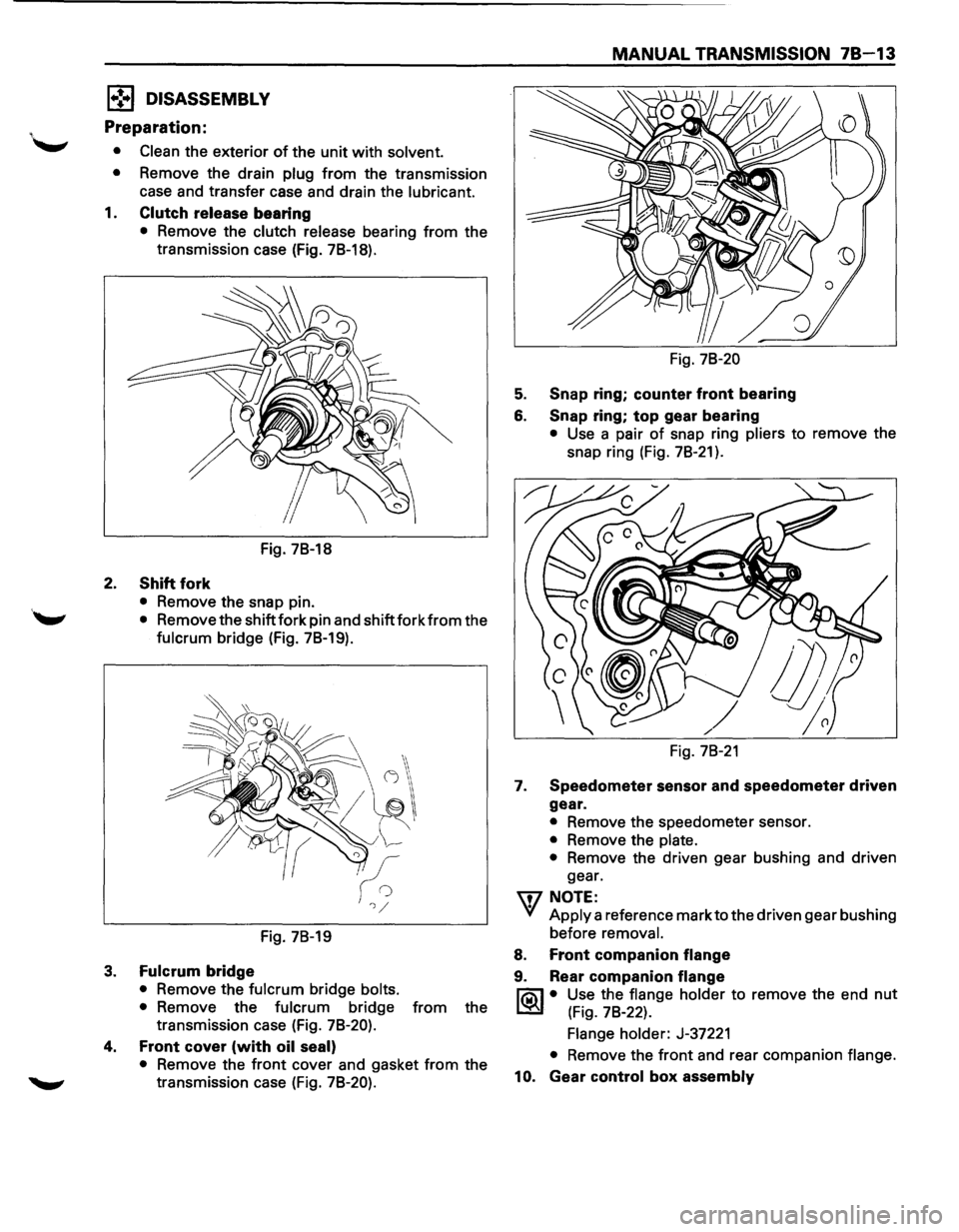
1. Clutch release bearing
• Remove the clutch release bearing from the
transmission case (Fig.
78-18).
Fig. 78-18
2. Shift fork
• Remove the snap pin.
''-" • Remove the shift fork pin and shift fork from the
fulcrum bridge (Fig. 78-19).
Fig. 78-19
3. Fulcrum bridge
• Remove the fulcrum bridge bolts.
•
Remove the fulcrum bridge from the
transmission case (Fig.
78-20).
4. Front cover (with oil seal)
• Remove the front cover and gasket from the
transmission case (Fig.
78-20).
MANUAL TRANSMISSION 78-13
Fig. 78-20
5. Snap ring; counter front bearing
6. Snap ring; top gear bearing
• Use a pair of snap ring pliers to remove the
snap ring (Fig.
78-21 ).
Fig. 78-21
1. Speedometer sensor and speedometer driven
gear.
• Remove the speedometer sensor.
• Remove the plate.
•
Remove the driven gear bushing and driven
gear.
'\fl NOTE:
VI Apply a reference mark to the driven gear bushing
before
removal.
8. Front companion flange
9. Rear companion flange
l'ia\1 • Use the flange holder to remove the end nut
~ (Fig. 78-22).
Flange holder: J-37221
• Remove the front and rear companion flange.
10. Gear control box assembly