drain bolt ISUZU TROOPER 1995 Workshop Manual
[x] Cancel search | Manufacturer: ISUZU, Model Year: 1995, Model line: TROOPER, Model: ISUZU TROOPER 1995Pages: 1928
Page 146 of 1928
381-8 POWER STEERING GEAR AND PUMP
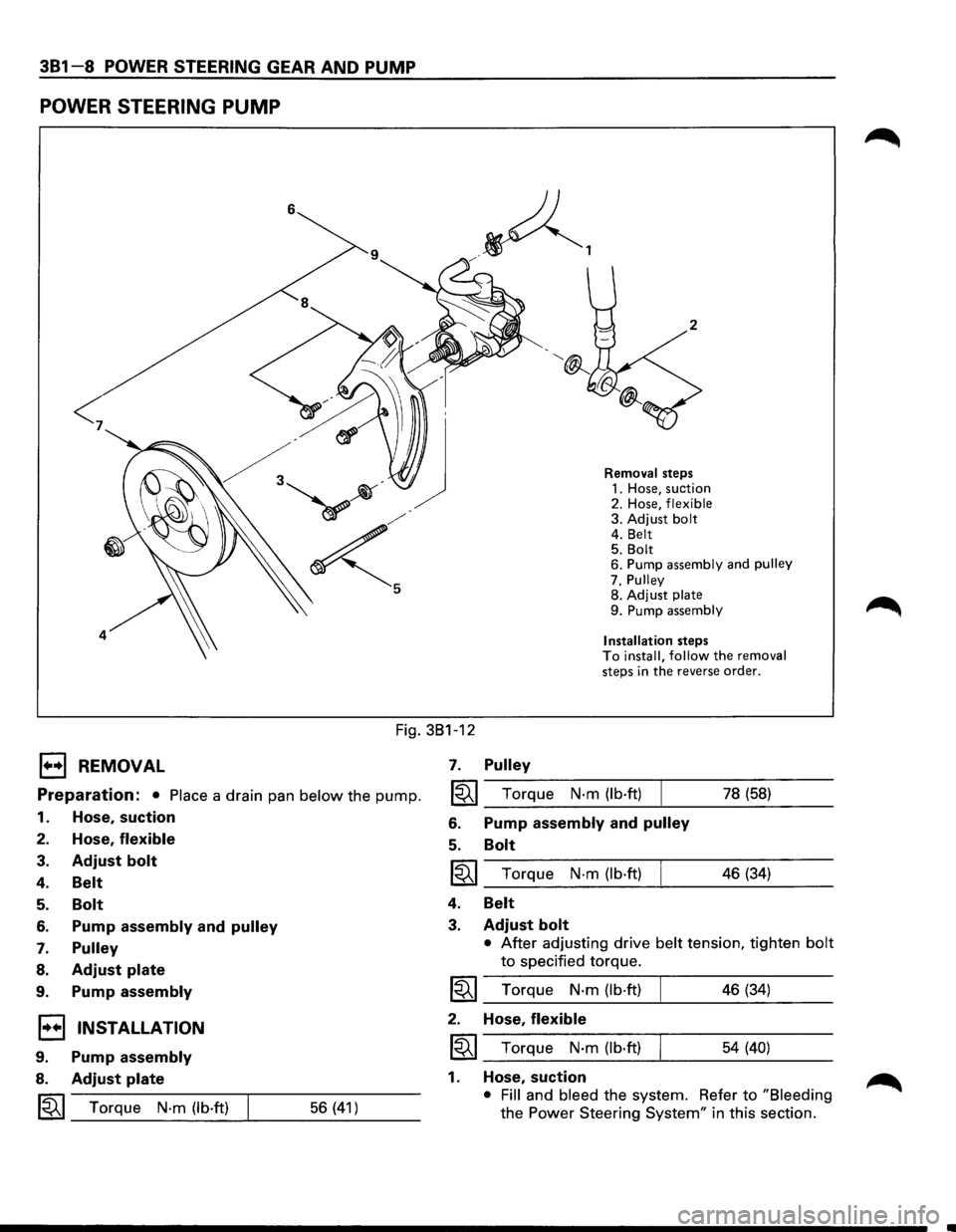
POWER STEERING PUMP
<
4
Removal steps
1. Hose, suction
2. Hose,
flexible 3. Adjust bolt 4. Belt 5. Bolt 6. Pump assembly and pulley
7. Pulley
8. Adjust
plate
9. Pump assembly
Installation
steps To install, follow the removal steps in the reverse order.
Fig. 381-12
B REMOVAL
Preparation: • Place a drain pan below the pump.
1. Hose, suction
2. Hose, flexible
3. Adjust bolt
4. Belt
5.
6.
7.
8.
9.
Bolt
Pump assembly and pulley
Pulley
Adjust plate
Pump assembly
1•+1 INSTALLATION
9. Pump assembly
8. Adjust plate
~~~ Torque N·m (lb·ft) 56 (41)
7. Pulley
~~~ Torque N·m (lb·ft)
6. Pump assembly and pulley
5. Bolt
~~~ Torque N·m (lb·ft)
4.
3.
Belt
Adjust bolt
78 (58)
46 (34)
• After adjusting drive belt tension, tighten bolt
to specified torque.
I~I_T_o_rq....:...u_e_N_·_m_(_lb_·ft_)____! ___ 4_6...:..(3_4...:_) __ _
2. Hose, flexible
~~~ Torque N·m (lb·ft) 54 (40)
1. Hose, suction
• Fill and bleed the system. Refer to "Bleeding
the Power Steering System" in this section.
Page 246 of 1928
48-4 REAR AXLE
ON-VEHICLE SERVICE
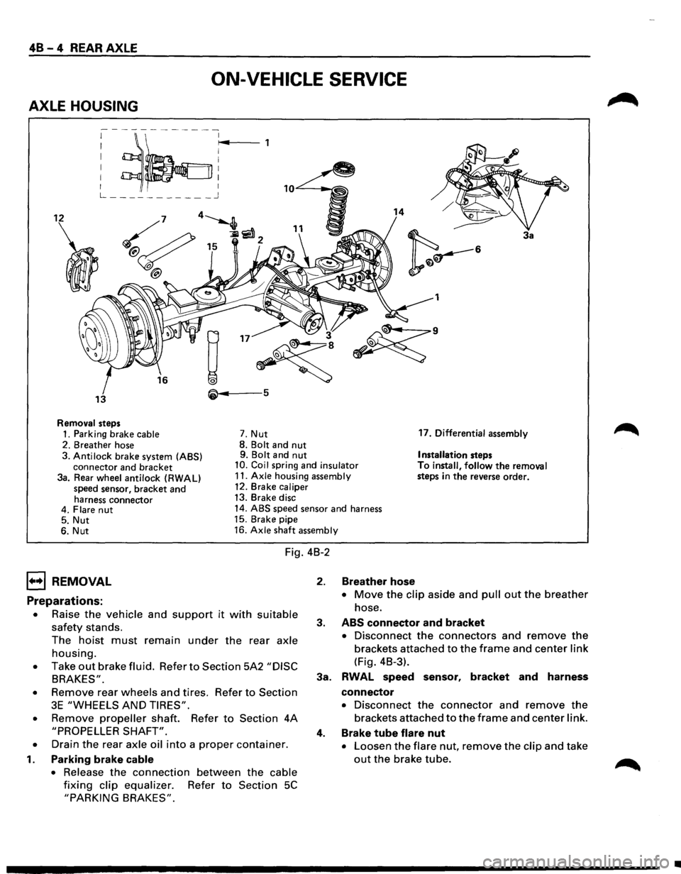
AXLE HOUSING
; ~~:r~4 ,
L ___________ j
12 14
3a
1
• 3
~
~·
13 5
Removal steps
1. Parking brake cable 7. Nut 17.
Differential assembly
2. Breather hose 8.
Bolt and nut 9. Bolt and nut Installation steps
3. Anti lock brake system (ABS)
connector and bracket 10. Coil spring and insulator To install, follow the removal
steps in the reverse order.
3a. Rear wheel antilock (RWAL)
speed sensor, bracket and
harness connector 11.
Axle housing assembly
12. Brake caliper
13. Brake disc
4. Flare
nut 14. ABS speed sensor and harness
5. Nut 15.
Brake pipe
6. Nut 16.
Axle shaft assembly
Fig. 4B-2
1••1 REMOVAL
Preparations:
• Raise the vehicle and support it with suitable
safety stands.
The
hoist must remain under the rear axle
housing.
• Take out brake fluid. Refer to Section 5A2 "DISC
BRAKES".
•
Remove rear wheels and tires. Refer to Section
3E "WHEELS AND TIRES".
•
Remove propeller shaft. Refer to Section 4A
"PROPELLER SHAFT".
•
Drain the rear axle oil into a proper container.
1. Parking brake cable
•
Release the connection between the cable
fixing clip equalizer. Refer to Section 5C
"PARKING BRAKES".
2. Breather hose
• Move the clip aside and pull out the breather
hose.
3. ABS connector and bracket
• Disconnect the connectors and remove the
brackets attached to the frame and center link
(Fig. 4B-3).
3a. RWAL speed sensor,
bracket and harness
connector
• Disconnect the connector and remove the
brackets attached to the frame and center link.
4. Brake tube flare nut
• Loosen the flare nut, remove the clip and take
out the brake tube.
•
Page 253 of 1928
E) INSTALLATION
5. Collapsible spacer
• Discard the used collapsible spacer and install
a new one.
4. Outer bearing
NOTE:
• Do not drive in, but just temporarily set in the
outer bearing
by hand, which should be
indirectly pressed in finally by tightening the
flange nut.
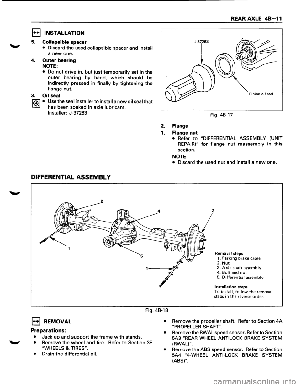
3. Oil seal
1"?.:\1 • Use the seal installer to install a new oil seal that
l.::::'i:il has been soaked in axle lubricant.
Installer:
J-37263
DIFFERENTIAL ASSEMBL V
~ 1
REAR AXLE 48-11
J-37263
Pinion oil seal
Fig. 4B-17
2. Flange
1. Flange nut
• Refer to "DIFFERENTIAL ASSEMBLY (UNIT
REPAIR)" for flange nut reassembly in this
section.
NOTE:
• Discard the used nut and install a new one.
3
/
Removal steps
1. Parking brake cable
2. Nut 3. Axle shaft assembly 4. Bolt and nut 5. Differential assembly
Installation
steps
To install, follow the removal steps in the reverse order.
Fig. 4B-18
E) REMOVAL
Preparations:
• Jack up and .support the frame with stands.
• Remove the wheel and tire. Refer to Section 3E
"WHEELS & TIRES".
•
Drain the differential oil. •
Remove
the propeller shaft. Refer to Section 4A
"PROPELLER SHAFT".
•
Remove the RWAL speed sensor. Refer to Section
5A3
"REAR WHEEL ANTILOCK BRAKE SYSTEM
(RWAL)".
•
Remove the ABS speed sensor. Refer to Section
5A4
"4-WHEEL ANTI-LOCK BRAKE SYSTEM
(ABS)".
Page 285 of 1928
l•!•l DISASSEMBLY
•
•
•
Jack up the vehicle and support it using jack
stands.
Remove the
tire and wheel.
Remove the drain bolt to drain differential oil.
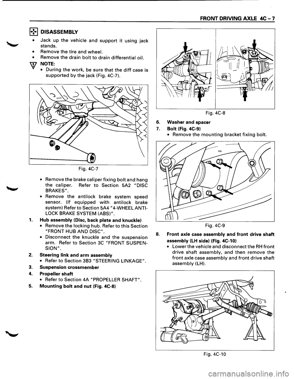
NOTE:
•
During the work, be sure that the diff case is
supported by the jack (Fig. 4C-7).
Fig.
4C-7
• Remov: the brake caliper fixing bolt and hang
the caliper. Refer to Section 5A2 "DISC
BRAKES".
•
Remove the antilock brake system speed
sensor.
(If equipped with antilock brake
system) Refer
to Section 5A4 "4-WHEEL ANTI
LOCK
BRAKE SYSTEM (ABS)".
1. Hub assembly (Disc, back plate and knuckle)
• Remove the locking hub. Refer to this Section
"FRONT HUB AND DISC".
•
Disconnect the knuckle and the suspension
arm. Refer
to Section 3C "FRONT SUSPEN
SION".
2. Steering link and arm assembly
• Refer to Section 3B3 "STEERING LINKAGE".
3. Suspension crossmember
4. Propeller shaft
• Refer to Section 4A "PROPELLER SHAFT".
5. Mounting bolt and nut (Fig. 4C-8)
FRONT DRIVING AXLE 4C-7
Fig. 4C-8
6. Washer and spacer
7. Bolt (Fig. 4C-9)
• Remove the mounting bracket fixing bolt.
Fig. 4C-9
8. Front axle case assembly and front drive shaft
assembly (LH side) (Fig. 4C-10)
• Lower the vehicle and disconnect the RH front
drive shaft assembly, and then remove the
front axle case assembly and front drive shaft
assembly (LH).
Fig. 4C-10
Page 301 of 1928
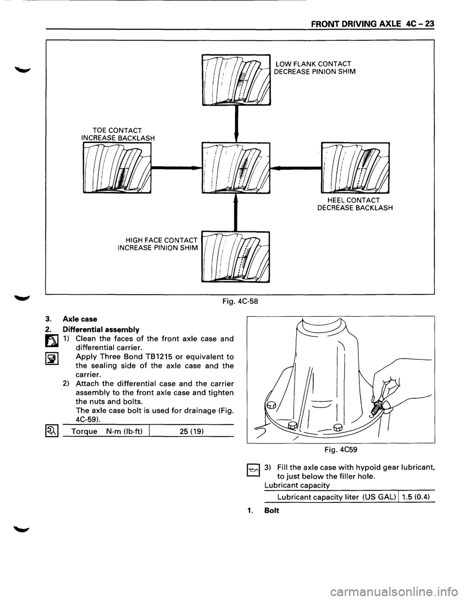
TOE CONTACT
INCREASE BACKLASH
HIGH FACE CONTACT 1
INCREASE PINION SHIM
FRONT DRIVING AXLE 4C-23
LOW FLANK CONTACT
DECREASE PINION SHIM
HEEL CONTACT
DECREASE BACKLASH
Fig. 4C-58
3. Axle case
2. Differential assembly
m 1) Clean the faces of the front axle case and
Lail differential carrier.
~~I Apply Three Bond TB1215 or equivalent to
the sealing side of the axle case and the
carrier.
2) Attach the differential case and the carrier
assembly to the front axle case and tighten
the nuts and bolts.
The axle case bolt is used for drainage (Fig.
4C-59).
~~~ Torque N-m (lb·ft) 25 (19)
Fig.
4C59
1~1 3) Fill the axle case with hypoid gear lubricant,
to just below the filler hole.
Lubricant capacity
Lubricant capacity liter (US GAL) 11.5 (0.4)
1. Bolt
Page 362 of 1928
5A2-14 DISC BRAKES
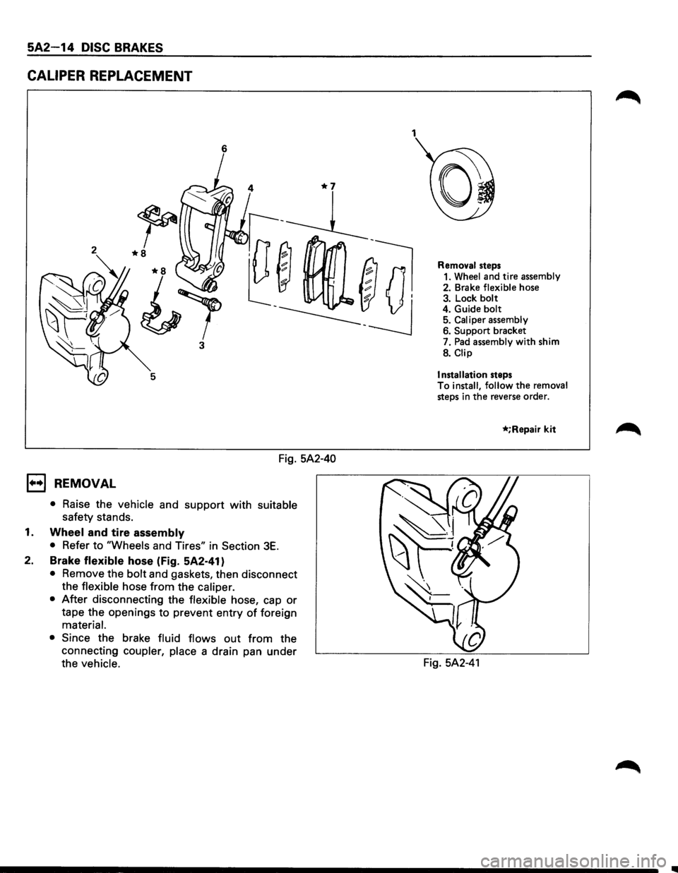
CALIPER REPLACEMENT
6
3
Fig. 5A2-40
1••1 REMOVAL
• Raise the vehicle and support with suitable
safety stands.
1. Wheel and tire assembly
• Refer to "Wheels and Tires" in Section 3E.
2. Brake flexible hose (Fig. 5A2-41)
• Remove the bolt and gaskets, then disconnect
the flexible hose
from the caliper.
• After disconnecting the flexible hose, cap or
tape the openings to prevent entry of foreign
material.
• Since the brake fluid flows out from the
connecting
coupler, place a drain pan under
the
vehicle.
1
Removal steps
1. Wheel and tire assembly
2. Brake flexible hose
3. Lock bolt 4. Guide bolt 5. Caliper assembly 6. Support bracket
7.
Pad assembly with shim
8.
Clip
Installation
steps
To install, follow the removal steps in the reverse order.
*;Repair kit
Fig. 5A2-41
Page 511 of 1928
ENGINE DIAGNOSIS 6-13
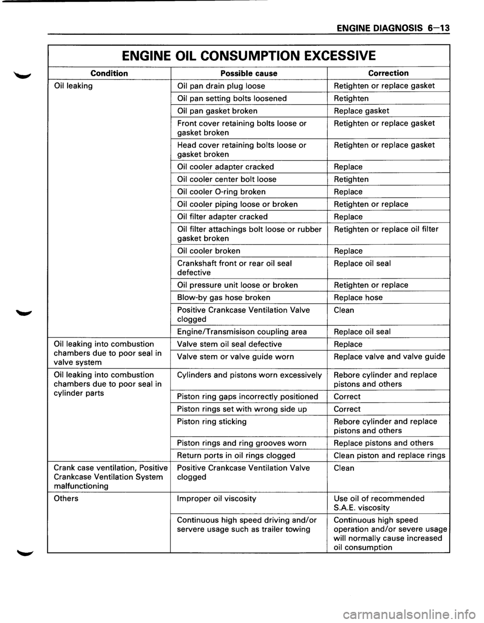
ENGINE OIL CONSUMPTION EXCESSIVE
Condition Possible cause Correction
Oil leaking
Oil pan drain plug loose Retighten or replace gasket
Oil pan setting bolts loosened Retighten
Oil pan gasket broken Replace gasket
Front cover retaining
bolts loose or Retighten or replace gasket
gasket broken
Head cover retaining
bolts loose or Retighten or replace gasket
gasket broken
Oil cooler adapter cracked Replace
Oil cooler
center bolt loose Retighten
Oil cooler 0-ring broken Replace
Oil cooler
piping loose or broken Retighten or replace
Oil filter
adapter cracked Replace
Oil filter
attachings bolt loose or rubber Retighten or replace oil filter
gasket broken
Oil cooler broken Replace
Crankshaft front or rear oil seal Replace oil seal
defective
Oil pressure unit loose or broken Retighten or replace
Blow-by
gas hose broken Replace hose
Positive Crankcase Ventilation
Valve
Clean
clogged
Engine/Transmisison coupling area Replace oil seal
Oil leaking
into combustion Valve stem oil seal defective Replace
chambers due to poor seal in Valve stem or valve guide worn Replace valve and valve guide valve system
Oil leaking into combustion
Cylinders and pistons worn excessively Rebore cylinder and replace
chambers
due to poor seal in pistons and others
cylinder parts
Piston ring gaps incorrectly positioned
Correct
Piston rings set
with wrong side up
Correct
Piston ring sticking Rebore
cylinder and replace
pistons and others
Piston rings and ring grooves
worn Replace pistons and others
Return ports in
oil rings clogged Clean piston
and replace rings
Crank case ventilation, Positive
Positive Crankcase Ventilation
Valve Clean
Crankcase Ventilation System clogged
malfunctioning
Others Improper oil viscosity
Use oil of recommended
S.A.E. viscosity
Continuous high speed driving
and/or Continuous high speed
servere usage such
as trailer towing operation and/or severe usage
will normally cause increased
oil consumption
Page 601 of 1928
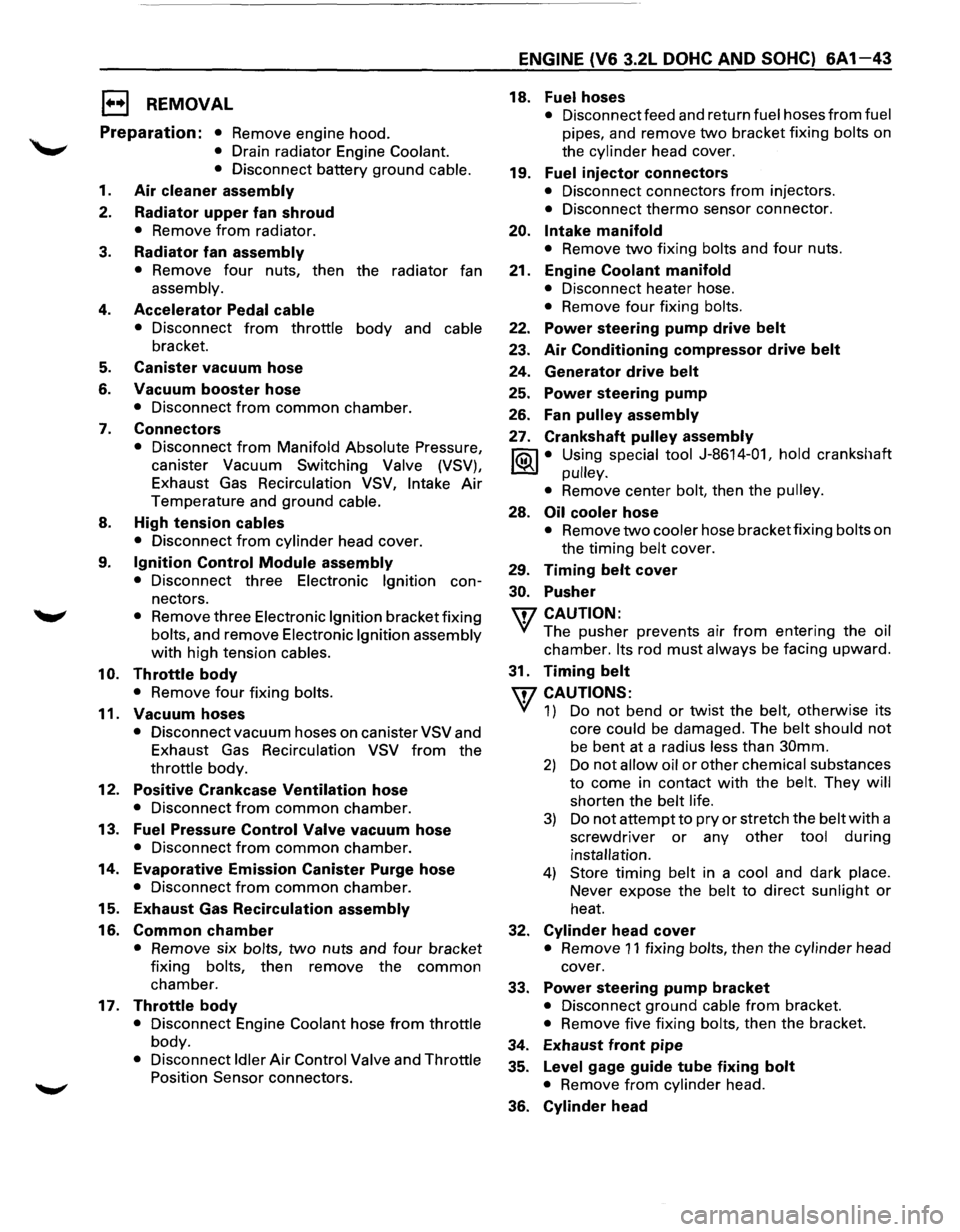
EJ REMOVAL
Preparation: • Remove engine hood.
• Drain radiator Engine Coolant.
• Disconnect battery ground cable.
1. Air cleaner assembly
2. Radiator upper fan shroud
• Remove from radiator.
3. Radiator fan assembly
• Remove four nuts, then the radiator fan
assembly.
4. Accelerator Pedal cable
• Disconnect from throttle body and cable
bracket.
5. Canister vacuum hose
6. Vacuum booster hose
• Disconnect from common chamber.
7. Connectors
• Disconnect from Manifold Absolute Pressure,
canister Vacuum Switching
Valve (VSV),
Exhaust Gas Recirculation VSV,
Intake Air
Temperature and ground cable.
8. High tension cables
• Disconnect from cylinder head cover.
9. Ignition Control Module assembly
• Disconnect three Electronic Ignition con
nectors.
• Remove three Electronic Ignition bracket fixing
bolts, and remove Electronic Ignition assembly
with high tension cables.
10. Throttle body
• Remove four fixing bolts.
11. Vacuum hoses
• Disconnect vacuum hoses on canister VSV and
Exhaust Gas Recirculation VSV
from the
throttle body.
12. Positive Crankcase Ventilation hose
• Disconnect from common chamber.
13. Fuel Pressure Control Valve vacuum hose
• Disconnect from common chamber.
14. Evaporative Emission Canister Purge hose
• Disconnect from common chamber.
15. Exhaust Gas Recirculation assembly
16. Common chamber
• Remove six bolts, two nuts and four bracket
fixing bolts, then remove the
common
chamber.
17. Throttle body
• Disconnect Engine Coolant hose from throttle
body.
• Disconnect Idler Air Control Valve and Throttle
Position Sensor connectors.
ENGINE (V6 3.2L DOHC AND SOHC) 6A1-43
18. Fuelhoses
• Disconnect feed and return fuel hoses from fuel
pipes, and remove two bracket fixing bolts on
the cylinder head cover.
19. Fuel injector connectors
• Disconnect connectors from injectors.
• Disconnect thermo sensor connector.
20. Intake manifold
• Remove two fixing bolts and four nuts.
21. Engine Coolant manifold
• Disconnect heater hose.
• Remove four fixing bolts.
22. Power steering pump drive belt
23. Air Conditioning compressor drive belt
24. Generator drive belt
25. Power steering pump
26.
Fan pulley assembly
27. Crankshaft pulley assembly
~ • Using special tool J-8614-01, hold crankshaft
~ pulley.
•
Remove center bolt, then the pulley.
28. Oil cooler hose
• Remove two cooler hose bracket fixing bolts on
the timing
belt cover.
29. Timing belt cover
30. Pusher
\fl CAUTION:
VI The pusher prevents air from entering the oil
chamber. Its rod must always be facing upward.
31. Timing belt
\fl CAUTIONS:
VI 1) Do not bend or twist the belt, otherwise its
core
could be damaged. The belt should not
be bent at a radius less than 30mm.
2) Do not allow oil or other chemical substances
to come in contact with the belt. They will
shorten the belt life.
3) Do not attempt to pry or stretch the belt with a
screwdriver
or any other tool during
installation.
4) Store timing belt in a cool and dark place.
Never expose the
belt to direct sunlight or
heat.
32. Cylinder head cover
• Remove 11 fixing bolts, then the cylinder head
cover.
33. Power steering pump bracket
• Disconnect ground cable from bracket.
• Remove five fixing bolts, then the bracket.
34. Exhaust front pipe
35.
Level gage guide tube fixing bolt
• Remove from cylinder head.
36. Cylinder head
Page 605 of 1928
1••1 REMOVAL
Preparation: • Remove engine hood.
• Drain radiator Engine Coolant.
•
Disconnect battery ground cable.
1.
Air cleaner assembly
2. Radiator upper fan shroud
• Remove from radiator.
3. Radiator fan assembly
• Remove four nuts, then the radiator fan
assembly.
4. Accelerator Pedal cable
• Disconnect from throttle body and cable
bracket.
5. Canister vacuum hose
• Disconnect from vacuum pipe.
6.
Vacuum booster hose
• Disconnect from common chamber.
7. Connectors
• Disconnect from Manifold Absolute Pressure,
canister Vacuum Switching Valve (VSV),
Exhaust
Gas Recirculation VSV, Intake Air
Temperature and ground cable.
8. High tension cables
• Disconnect from cylinder head cover.
9. Ignition Control Module assembly
• Disconnect three Electronic Ignition con
nectors.
• Remove three Electronic Ignition bracket fixing
bolts, and remove Electronic
Ignition assembly
with high tension cables.
10. Throttle body
• Remove four fixing bolts.
11.
Vacuum hoses
• Disconnect vacuum hoses on canister VSV and
Exhaust
Gas Recirculation VSV from the
throttle body.
12.
Positive Crankcase Ventilation hose
• Disconnect from common chamber.
13. Fuel Pressure
Control Valve vacuum hose
• Disconnect from common chamber.
14.
Canister vacuum hose
• Disconnect from common chamber.
15.
Exhaust Gas Recirculation Valve assembly
• Remove five bolts from common chamber,
exhaust manifold and cylinder head cover.
16.
Common chamber duct
• Remove four bolts, four nuts and three bracket
fixing bolts, then remove the
common
chamber.
• Disconnect ground cable from rear side of
common chamber.
ENGINE (V6 3.2L DOHC AND SOHC) 6A1 47
17. Throttle body
• Disconnect Engine Coolant hose from throttle
body.
• Disconnect Idle Air Control Valve and Throttle
Position Sensor connectors.
18.
Common chamber
• Remove six bolts and two nuts.
• Remove fixing bolts on common chamber
bracket, then the
common chamber.
19.
Fuelhoses
• Disconnect feed and return fuel hoses from fuel
pipes, and remove
two bracket fixing bolts on
the cylinder head cover.
20. Fuel injector connectors
• Disconnect connectors from injectors.
• Disconnect thermo sensor connector.
21.
Intake manifold
• Remove two fixing bolts and four nuts.
22. Engine
Coolant manifold
• Disconnect heater hose.
• Remove four fixing bolts.
23.
Power steering pump drive belt
24. Air Conditioning compressor drive belt
25. Generator drive belt
26. Power steering pump
27. Fan pulley assembly
28. Crankshaft pulley assembly
I®J • Using special tool J-8614-01, hold crankshaft
pulley.
•
Remove center bolt, then the pulley.
29. Oil cooler hose
• Remove two cooler hose bracket fixing bolts on
the timing belt cover.
30. Timing belt cover
31. Pusher
CAUTION:
The pusher prevents air from entering the oil
chamber. Its rod must always be facing upward.
32.
Timing belt
w CAUTIONS:
' 1) Do not bend or twist the belt, otherwise its
core could
be damaged. The belt should not
be bent at a radius less than 30mm.
2) Do not allow oil or other chemical substances
to come in contact
with the belt. They will
shorten the belt life.
3) Do not attempt to pry or stretch the belt with a
screwdriver
or any other tool during
installation.
4) Store timing belt in a cool and dark place.
Never expose the belt to direct sunlight
or
heat.
Page 608 of 1928
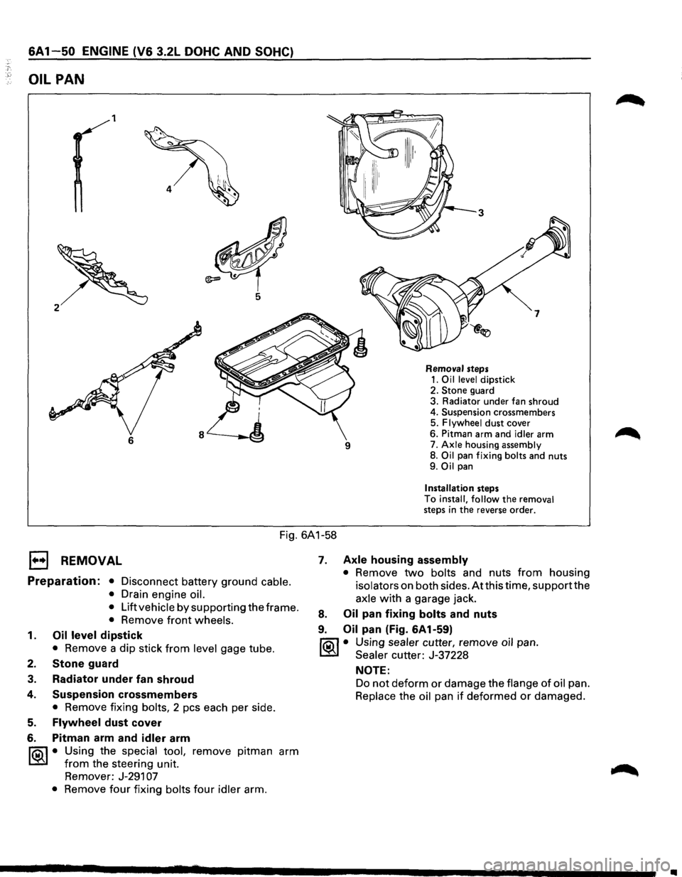
6A1 50 ENGINE (V6 3.2L DOHC AND SOHC)
OIL PAN
1
6
Removal steps 1. Oil level dipstick
2. Stone guard
3. Radiator under fan shroud
4. Suspension crossmembers
5.
Flywheel dust cover
6. Pitman arm and
idler arm
7. Axle housing assembly 8. Oil pan fixing bolts and nuts
9. Oil pan
Installation steps
To install, follow the removal steps in the reverse order.
Fig. 6A1-58
1••1 REMOVAL
Preparation: • Disconnect battery ground cable.
•
Drain engine oil.
•
Lift vehicle by supporting the frame.
• Remove front wheels.
1. Oil level dipstick
• Remove a dip stick from level gage tube.
2. Stone guard
3. Radiator under fan shroud
4.
5.
6.
Suspension crossmembers
• Remove fixing bolts, 2 pes each per side.
Flywheel dust cover
Pitman arm and
idler arm
~·
Using the special tool, remove pitman arm
from the steering unit.
Remover: J-291
07
• Remove four fixing bolts four idler arm.
7. Axle housing assembly
• Remove two bolts and nuts from housing
isolators on both sides. Atthis time, supportthe
axle with a garage jack.
8. Oil pan fixing bolts and nuts
9. Oil pan (Fig. 6A1-59)
fiOil • Using sealer cutter, remove oil pan.
~ Sealer cutter: J-37228
NOTE:
Do not deform or damage the flange of oil pan.
Replace the oil pan if deformed or damaged.
•