fuel filter ISUZU TROOPER 1995 User Guide
[x] Cancel search | Manufacturer: ISUZU, Model Year: 1995, Model line: TROOPER, Model: ISUZU TROOPER 1995Pages: 1928
Page 561 of 1928
CYLINDER BLOCK
The cylinder block is made of aluminum die-cast
casting
for 75° V-type six cylinders. It has a rear plate
integrated structure and employs a deep skirt. The
cylinder liner is cast and the liner inner diameter and
crankshaft
journal diameter are classified into grades.
The crankshaft is supported by four bearings
of which
width is different between No.2, No.3 and No.1, No.4;
the
width of No.3 bearing on the body side is different
in order
to support the thrust bearing. The bearing cap
is made
of nodular cast iron and each bearing cap uses
four bolts and two side bolts.
CYLINDER HEAD
The cylinder head, made of aluminum alloy casting
employs a pent-roof type combustion chamber with a
spark
plug in the center.
The intake and exhaust
valves are placed in V-type
design. The ports are cross-flow type.
VALVE TRAIN
SOHC: The camshafts on both banks are driven by a
timing
belt to operate the valves via rocker arm.
No
further valve clearance adjustment is
required, due
to the Hydraulic lash adjuster
attachedtotherockerarm.
DOHC: Intake camshaft on the both sides of banks are
driven through a
timing belt, while exhaust
camshaft are driven by the both sides
of intake
camshaft through chains.
The driven camshafts open and
close valves
through swing arms.
Valve clearance is automatically adjusted by
means
of HLA built in the cylinder head.
INTAKE MANIFOLD
SOHC: The intake manifold system is composed ofthe
aluminum cast common chamber and intake
manifold attached with six fuel injectors.
DOHC: The intake manifold system is composed of the
aluminum cast common chamber duct having
the induction
control valve, common chamber
and intake
manifold attached with six fuel
injectors.
EXHAUST MANIFOLD
The exhaust manifold is made of nodular cast iron.
PISTONS AND CONNECTING RODS
Aluminum pistons are used after selecting the grade
that meets the cylinder bore diameter. Each piston has
two compression rings and one oil ring. The piston pin
made
of chromium steel is offset 1 mm toward the
thrust side, and the thrust pressure
of piston to the
cylinder wall varies gradually as the piston travels. The
connecting rods are made
of forged steel. The
connecting rod bearings are graded
for correct size
selection.
ENGINE (V6 3.2L DOHC AND SOHC) 6A1-3
CRANKSHAFT AND BEARINGS
The crankshaft is made of Ductile cast-iron.Pins and
journals are graded for correct size selection for their
bearing.
OIL PUMP
The trochoid-type oil pump is driven by crankshaft.
Operation and service procedures are described in this
section.
ENGINE LUBRICATION
The oil discharged by a trochoid-type oil pump driven
by the crankshaft is fed through full-flow oil filter and
engine
coolant cooled oil cooler up to the oil gallery
provided under the crankshaft bearing cap. The oil is
then
led to the crankshaft journals and cylinder head.
The crank pins are
lubricated with oil from crankshaft
journals through oil holes. Also, an oil jet is fed to each
cylinder from crankshaft journals on the connecting
rod
for piston cleaning. The oil pan flange is sealed with
liquid packing only; do not deform or damage the
flange surface during removal or installation.
Page 643 of 1928
ENGINE FUEL 6C-1
SECTION 6C
ENGINE FUEL
CONTENTS
General Description ....................... .
Fuel Metering ............................ .
On-Vehicle Service ........................ .
Fuel Filter ................................. .
In Tank Fuel Filter ............................. .
Fuel Pump Flow Test ........................ .
Fuel Pump Assembly ........................ .
Fuel Pump Relay .............................. ..
6C-1
6C-2
6C-3
6C-3
6C-4
6C-4
6C-5
6C-5
Fuel Tank .......................................... ..
Fuel Gage Unit ................................. ..
Fuel Filler Cap .................................... .
Accelerator Pedal Control ............... ..
Accelerator Pedal Control Cable ..
Accelerator Pedal ......................... .
Air
Cleaner Filter ........................... .
Main Data and Specifications ............... .
Torque Specifications ......................
..
6C-6
6C-7
6C-7
6C-8
6C-8
6C-9
6C-10
6C-11
6C-11
GENERAL DESCRIPTION
When working on the fuel system, there are several
things to keep in mind:
• Any time the fuel system is being worked on,
disconnect the negative battery
cable except for
those tests where battery voltage is required.
• Always keep a dry chemical (Class 8) fire extin
guisher near the work area.
• Replace all pipes with the same pipe and fittings
that were removed.
• Clean and inspect "0" rings. Replace if required.
• Always relieve the line pressure before servicing
any fuel system components.
• Do not attempt repairs on the fuel system until you
have read the instructions and checked the pic
tures
relating to that repair.
• Adhere to all Notices and Cautions.
All gasoline engines are designed to use only unleaded
gasoline. Unleaded gasoline
must be used for proper
emission control system operation. Its use will also
minimize spark plug fouling and extend engine oil life.
Using leaded gasoline can damage the emission
control system and could result in loss of emission
warranty coverage.
All cars are equipped with an Evaporative Emission
Control System. The purpose of the system is to
minimize the escape offuel vapors to the atmosphere.
Information on this system will be found in Section
6E2.
Page 645 of 1928
ENGINE FUEL 6C - 3
ON-VEHICLE SERVICE
When repair to the fuel system has been com
pleted, start engine and check the fuel system for
FUEL FILTER
2
3
loose connection or leakage. For the fuel system
diagnosis, see Section 6E.
Receive rubber
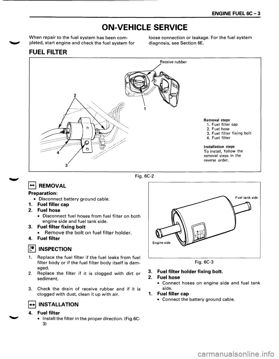
Rer:noval steps 1. Fuel filler cap 2. Fuel hose
3. Fuel filter fixing bolt
4. Fuel filter
Installation steps To install, follow the removal steps in the
reverse order.
Fig. 6C-2
EJ REMOVAL
Preparation:
• Disconnect battery ground cable.
1. Fuel filler cap
2. Fuel hose
• Disconnect fuel hoses from fuel filter on both
engine side and fuel tank side.
3. Fuel filter fixing bolt
•
Remove the bolt on fuel filter holder.
4. Fuel filter
(1!] INSPECTION
1. Replace the fuel filter if the fuel leaks from fuel
filter body or if the fuel filter body itself is dam
aged.
2. Replace the filter if it is clogged with dirt or
sediment.
3. Check the drain of receive rubber and if it is
clogged with dust, clean it up with air.
B INSTALLATION
4. Fuel filter
.......,. • Install the filter in the proper direction. (Fig.6C-
3)
Fig. 6C-3
3. Fuel filter holder fixing bolt.
2. Fuel hose
• Connect hoses on engine side and fuel tank
side.
1. Fuel filler cap
• Connect the battery ground cable.
Page 646 of 1928
![ISUZU TROOPER 1995 User Guide 6C - 4 ENGINE FUEL
I1!]1NSPECTION
After installation, start engine and check for fuel leak
age.
IN-TANK FUEL FILTER
The filter is located on the lower end of fuel pickup
tube in the fuel tank](/img/61/57183/w960_57183-645.png "ISUZU TROOPER 1995 User Guide 6C - 4 ENGINE FUEL
I1!]1NSPECTION
After installation, start engine and check for fuel leak
age.
IN-TANK FUEL FILTER
The filter is located on the lower end of fuel pickup
tube in the fuel tank")
6C - 4 ENGINE FUEL
I1!]1NSPECTION
After installation, start engine and check for fuel leak
age.
IN-TANK FUEL FILTER
The filter is located on the lower end of fuel pickup
tube in the fuel tank. It prevents dirt from entering the
fuel pipe and also stops water unless the filter is
completely submerged in the water. It is a self-cleaning
type, not requiring scheduled maintenance. Excess
water and sediment in the tank restricts fuel supply to
the engine, resulting in engine stop. In such a case, the
tank
must be cleaned throughly.
FUEL PUMP FLOW TEST
If reduction of fuel supply is suspected, perform
checking as follows.
Preparation:
• Make sure that there is fuel in the tank.
• With the engine running, check the fuel feed
pipe and hose
from fuel tank to injector for
evidence of leakage.
Retighten, if pipe or hose connection is loose.
Also,
check pipes and hoses for squashing or
clogging.
1. Receive the hose from fuel feed pipe with a clean
container, and check for fuel pump flow rate.
2. Connect the pump relay terminals with a jumper
wire as shown and start the fuel pump to measure
delivery. (Fig. 6C-4)
W CAUTION:
Never generate sparks when connecting a jumper
wire.
Fig. 6C-4
Delivery Delivery
15 seconds 0.38
liters minimum
If the measure value is out of standard, conduct the
pressure test.
Pressure test
For the pressure test to the fuel system, see Section 6E
"Fuel Control System".
II
Page 652 of 1928
6C -10 ENGINE FUEL
Adjustment of pedal stroke
Manual Transmission:
• Rotate counterclockwise to loosen the stopper
bolt sufficiently.
• Fully depress the pedal and hold it there hand.
Next, rotate the stopper bolt until it hits the
stopper of pedal bracket. Then, lock the stopper
bolt there.
Automatic Transmission:
• Rotate counterclockwise to loosen the kickdown
switch sufficiently.
• Fully depress the pedal and hold it there hand.
Rotate
the switch clockwise and then rotate
further by 1/2 turn from the position where the
switch clicks. Lock the switch there.
• Step on the accelerator pedal and make sure that
you can hear clicking sound at the full stroke
position.
AIR CLEANER FILTER
EJ REMOVAL
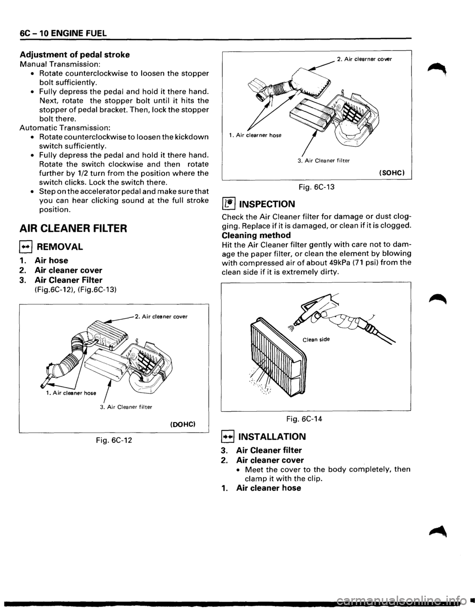
1. Air hose
2. Air cleaner cover
3. Air Cleaner Filter
(Fig.6C-12), (Fig.6C-13)
2. Air cleaner cover
3. Air Cleaner filter
(DOHC)
Fig. 6C-12
2. Air clearner cover
3.
Air Cleaner filter
(SOHC)
Fig. 6C-13
~ INSPECTION
Check the Air Cleaner filter for damage or dust clog
ging. Replace if it is damaged, or clean if it is clogged.
Cleaning method
Hit the Air Cleaner filter gently with care not to dam
age the paper filter, or clean the element by blowing
with compressed air of about 49kPa (71 psi) from the
clean side if it is extremely dirty.
Fig. 6C-14
8 INSTALLATION
3. Air Cleaner filter
2. Air cleaner cover
• Meet the cover to the body completely, then
clamp it with the clip.
1. Air cleaner hose
•
Page 702 of 1928
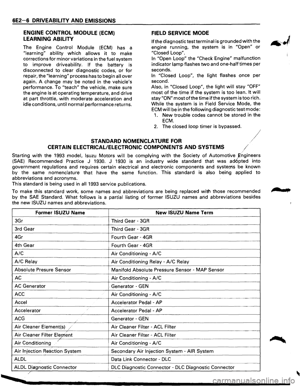
6E2-6 DRIVEABILITY AND EMISSIONS
FIELD SERVICE MODE
ENGINE
CONTROL MODULE (ECM)
LEARNING ABILITY
The Engine Control Module (ECM) has a
"learning"
ability which allows it to make
corrections
for minor variations in the fuel system
to improve driveability. If the battery is
disconnected to clear diagnostic codes, or for
repair, the "learning" process has to begin all over
again. A change
may be noted in the vehicle's
performance. To "teach" the vehicle, make sure
the engine is at operating temperature, and drive
at part throttle, with moderate acceleration and
idle conditions, until normal performance returns.
lfthe diagnostic test terminal is grounded with the
engine running, the system is in
"Open" or
"Closed Loop".
In "Open Loop" the "Check Engine" malfunction
indicator lamp flashes
two and one-halftimes per
seconds.
In "Closed Loop", the light flashes once per
second.
Also, in "Closed
Loop", the light will stay "OFF"
most of the time if the system is too lean. It will
stay"ON" mostofthetime if the system is too rich.
While the system is in Field Service Mode, the
ECM will be in the following diagnostic test mode:
1. New trouble codes cannot be stored in the
ECM.
2. The closed loop timer is bypassed.
STANDARD NOMENCLATURE FOR /
CERTAIN ELECTRICAL/ELECTRONIC COMPONENTS AND SYSTEMS /
Starting with the 1993 model, lsuzu Motors will be complying with the Society of Automotive ~ngineers
(SAE) Recommended Practice J 1930. J 1930 is an industry wide standard that was ad6pted into
government regulations and requires certain electrical and electronic components and
syster;ns be known
by the same
nomenclature that have the same function. This standard is also being applied to
abbreviations and acronyms.
This standard is being used in
all 1993 service publications.
To make this standard work, some names and abbreviations are being replaced
with those recommended
by the
SAE Standard. What follows is a partial listing of former ISUZU names and abbreviations besides
the
new ISUZU names and abbreviations.
Former ISUZU Name New ISUZU Name Term
3Gr
Third Gear -3GR
3rd Gear
Third Gear -3GR
4Gr
Fourth Gear -4GR
4th Gear
Fourth Gear -4GR
A/C Air Conditioning -A/C
A/C
Relay Air Conditioning Relay -A/C Relay
Absolute Presure Sensor
Manifofd Absolute Pressure Sensor -MAP Sensor
AC Air Conditioning -A/C
AC Generator . Generator -GEN
ACC Air Conditioning -A/C
Accel
Accelerator Pedal -AP
Accelerator
Accelerator Pedal -AP
ACG Generator -GEN
Air Cleaner Element(s) / Air Cleaner Filter -ACL Filter
Air Cleaner Filter Ele;nent Air Cleaner Filter -ACL Filter
Air Conditioning / Air Conditioning -A/C
Air Injection Reaction System Secondary Air Injection System -AIR System
ALDL Data Link Connector -
DLC
ALDL Diagnostic Connector DLC Diagnostic Connector -DLC Diagnostic Connector ,.
, ....
Page 746 of 1928
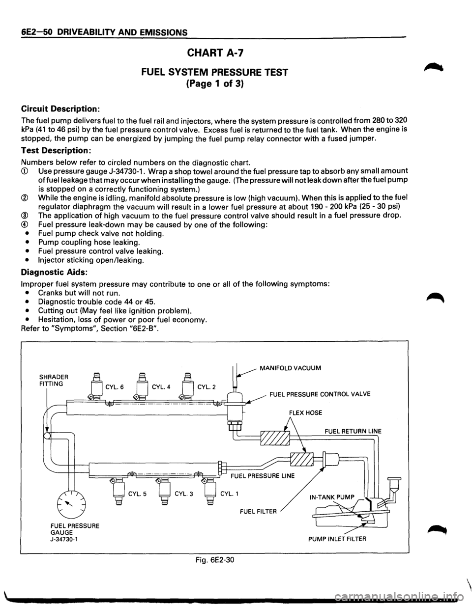
6E2-50 DRIVEABILITY AND EMISSIONS
Circuit Description:
CHART A-7
FUEL SYSTEM PRESSURE TEST
(Page 1 of 3)
The fuel pump delivers fuel to the fuel rail and injectors, where the system pressure is controlled from 280 to 320
kPa (41 to 46 psi) by the fuel pressure control valve. Excess fuel is returned to the fuel tank. When the engine is
stopped, the
pump can be energized by jumping the fuel pump relay connector with a fused jumper.
Test Description:
Numbers below refer to circled numbers on the diagnostic chart.
CD Use pressure gauge J-34730-1. Wrap a shop towel around the fuel pressure tap to absorb any small amount
offuelleakage that may occur when installing the gauge. (The pressure will not leak down after the fuel pump
is stopped on a correctly functioning system.)
® While the engine is idling, manifold absolute pressure is low (high vacuum). When this is applied to the fuel
regulator
diaphragm the vacuum will result in a lower fuel pressure at about 190-200 kPa (25-30 psi)
@ The application of high vacuum to the fuel pressure control valve should result in a fuel pressure drop.
@ Fuel pressure leak-down may be caused by one of the following:
• Fuel
pump check valve not holding.
•
Pump coupling hose leaking.
• Fuel
pressure control valve leaking.
• Injector
sticking open/leaking.
Diagnostic Aids:
Improper fuel system pressure may contribute to one or all of the following symptoms:
• Cranks but will not run.
• Diagnostic trouble code 44 or 45.
• Cutting out (May feel like ignition problem).
•
Hesitation, loss of power or poor fuel economy.
Refer
to "Symptoms", Section "6E2-B".
SHRADER FITTING
FUEL PRESSURE
GAUGE
J-34730-1
Fig. 6E2-30
MANIFOLD VACUUM
FUEL PRESSURE CONTROL VALVE
FUEL RETURN LINE
FUEL FILTER
PUMP INLET FILTER
Page 748 of 1928
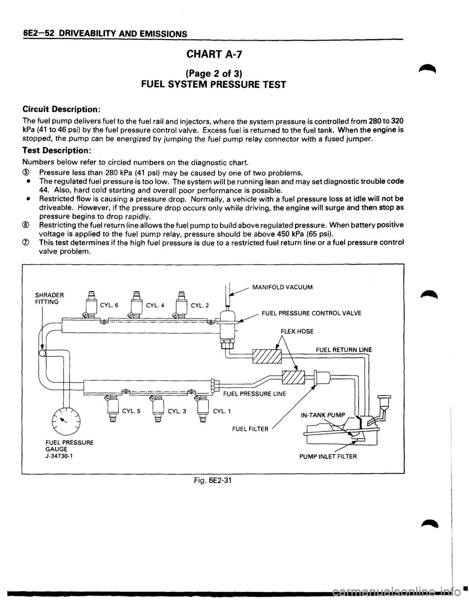
6E2-52 DRIVEABILITV AND EMISSIONS
CHART A-7
(Page 2 of 3)
FUEL SYSTEM PRESSURE TEST
Circuit Description:
The fuel pump delivers fuel to the fuel rail and injectors, where the system pressure is controlled from 280 to 320
kPa (41 to 46 psi) by the fuel pressure control valve. Excess fuel is returned to the fuel tank. When the engine is
stopped, the
pump can be energized by jumping the fuel pump relay connector with a fused jumper.
Test Description:
Numbers below refer to circled numbers on the diagnostic chart.
® Pressure less than 280 kPa (41 psi) may be caused by one of two problems.
• The regulated fuel pressure is too low. The system will be running lean and may set diagnostic trouble code
44. Also, hard cold starting and overall poor performance is possible.
• Restricted flow is causing a pressure drop. Normally, a vehicle with a fuel pressure loss at idle will not be
driveable. However,
if the pressure drop occurs only while driving, the engine will surge and then stop as
pressure begins to drop rapidly.
® Restricting the fuel return line allows the fuel pump to build above regulated pressure. When battery positive
voltage is applied to the fuel pump relay, pressure should
be above 450 kPa (65 psi).
® This test determines if the high fuel pressure is due to a restricted fuel return line or a fuel pressure control
valve problem.
SHRADER FITIING
FUEL PRESSURE GAUGE J-34730-1
Fig. 6E2-31
MANIFOLD VACUUM
FUEL PRESSURE CONTROL VALVE
FUEL RETURN
LINE
FUEL FILTER
PUMP INLET FILTER
•
Page 749 of 1928
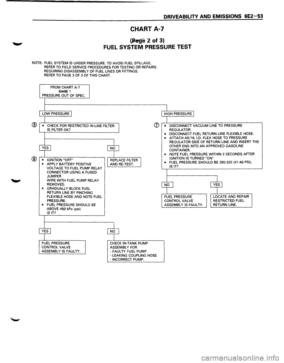
DRIVEABILITV AND EMISSIONS 6E2-53
CHART A-7
(P«ge 2 of 3)
FUEL SYSTEM PRESSURE TEST
NOTE: FUEL SYSTEM IS UNDER PRESSURE. TO AVOID FUEL SPILLAGE, REFER TO FIELD SERVICE PROCEDURES FOR TESTING OR REPAIRS
REQUIRING DISASSEMBLY OF FUEL LINES OR FITIINGS. REFER TO PAGE 3 OF 3 OF THIS CHART.
FROM CHART A-7 E!A:8E 1 PRESSURE OUT OF SPEC.
LOW PRESSURE I
(j) • CHECK FOR RESTRICTED IN-LINE FILTER. I IS FILTER OK?
® ~ $
• IGNITION "OFF"
REPLACE FILTER I • APPLY BATIERY POSITIVE AND RE-TEST.
VOLTAGE TO FUEL PUMP RELAY CONNECTOR USING A FUSED JUMPER
WIRE WITH FUEL PUMP RELAY
REMOVED.
• GRADUALLY BLOCK FUEL
RETURN LINE BY PINCHING
FLEXIBLE HOSE AND NOTE FUEL PRESSURE.
• FUEL PRESSURE SHOULD BE ABOVE 450 kPa (psi) IS IT?
~ $
FUEL PRESSURE CHECK IN-TANK PUMP
CONTROL VALVE ASSEMBLY FOR ASSEMBLY IS FAULTY.
-FAULTY FUEL PUMP -LEAKING COUPLING HOSE -INCORRECT PUMP. HIGH
PRESSURE
I
• DISCONNECT VACUUM LINE TO PRESSURE REGULATOR. • DISCONNECT FUEL RETURN LINE FLEXIBLE HOSE.
• ATIACH AS/16. I.D. FLEX HOSE TO PRESSURE REGULATOR SIDE OF RETURN LINE AND INSERT THE OTHER END INTO AN APPROVED GASOLINE
CONTAINER.
• NOTE FUEL PRESSURE WITHIN 2 SECONDS AFTER IGNITION IS TURNED "ON" • FUEL PRESSURE SHOULD BE 280-320 (41-46 PSI).
IS IT?
CfJ ~ FUEL PRESSURE LOCATE AND REPAIR
CONTROL VALVE RESTRICTED FUEL ASSEMBLY IS FAULTY. RETURN LINE.
Page 750 of 1928
6E2-54 DRIVEABILITY AND EMISSIONS
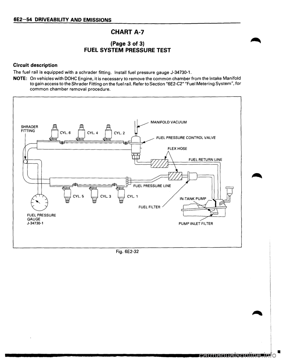
Circuit
description
CHART A-7
(Page 3 of 3)
FUEL SYSTEM PRESSURE TEST
The fuel rail is equipped with a schrader fitting. Install fuel pressure gauge J-34730-1.
NOTE: On vehicles with DOHC Engine, it is necessary to remove the common chamber from the Intake Manifold
to gain access to the Shrader Fitting on the fuel rail. Refer to Section "6E2-C2" "Fuel Metering System", for
common chamber removal procedure.
SHRADER FITIING
FUEL PRESSURE
GAUGE
J-34730-1
Fig. 6E2-32
MANIFOLD VACUUM
FUELPRESSURECONTROLVALVE
FUEL RETURN LINE
FUEL FILTER
PUMP INLET FIL TEA
•