manual transmission ISUZU TROOPER 1995 User Guide
[x] Cancel search | Manufacturer: ISUZU, Model Year: 1995, Model line: TROOPER, Model: ISUZU TROOPER 1995Pages: 1928
Page 429 of 1928
4-WHEEL ANTILOCK BRAKE SYSTEM (ABS) 5A4-19
MODE F3: SNAPSHOT
This mode is used to store the data displayed by MODE FO: DATA LIST during system operation. You can
then review the information and compare it to specifications, to find any unusual conditions.
The
trigger point must be manually input by the TECH 1 operator, by "F9" key.
SNAPSHOT OPTIONS
FO: NOT USED
Fl: NOT USED
F2: MANUAL TRIG.
For further details please refer to the Operators Manual for TECH 1 "ISUZU 90-94 TRANSMISSION/ASS
CARTRIDGE".
Page 619 of 1928
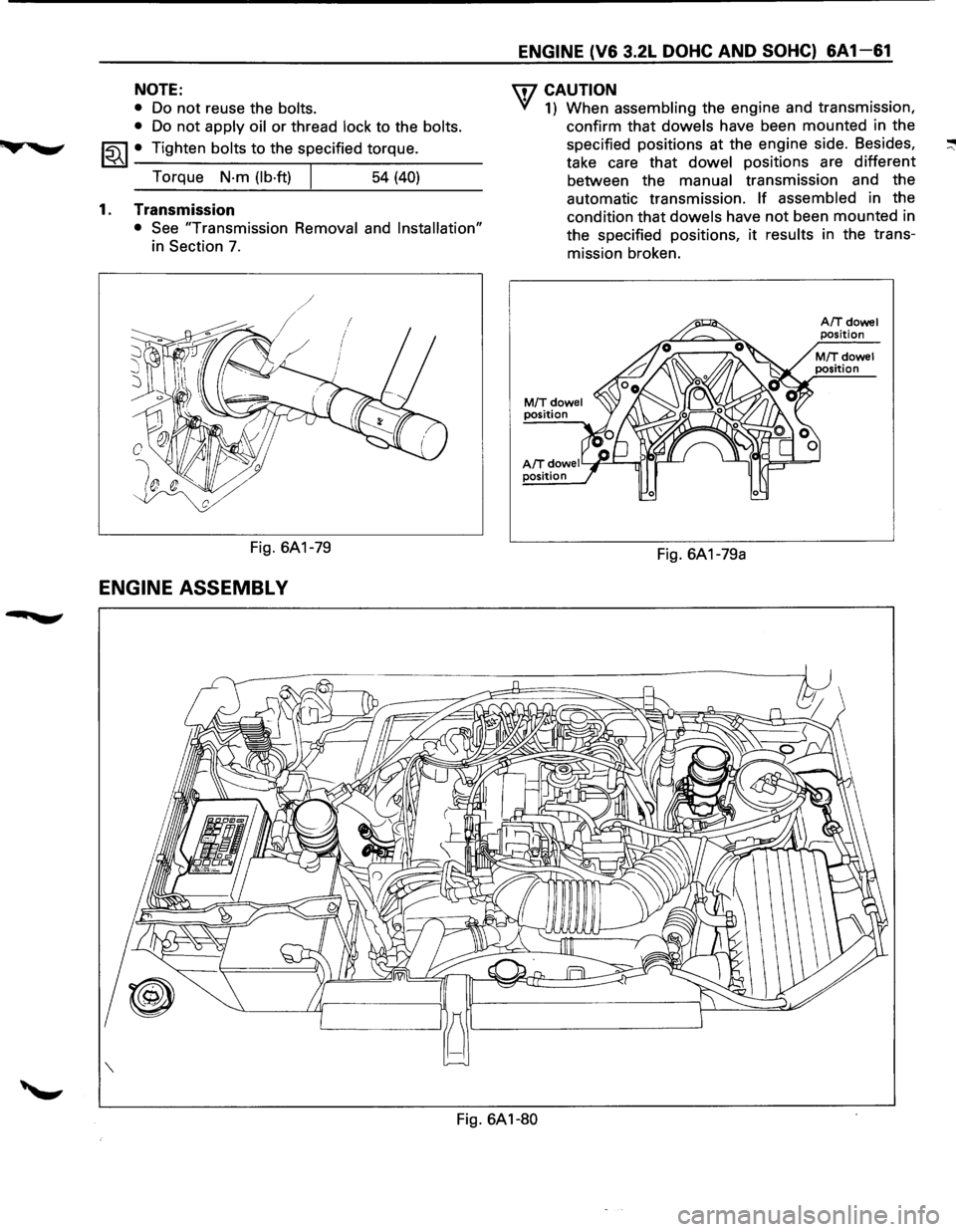
NOTE:
• Do not reuse the bolts.
•
Do not apply oil or thread lock to the bolts.
~~~ • Tighten bolts to the specified torque.
Torque
N·m (lb·ft) 54 (40)
1. Transmission
• See "Transmission Removal and Installation"
in Section 7.
Fig. 6A1-79
ENGINE ASSEMBL V
ENGINE (V6 3.2L DOHC AND SOHC) 6A 1-61
U7 CAUTION
VI 1) When assembling the engine and transmission,
confirm that
dowels have been mounted in the
specified positions at the engine side. Besides,
take care that
dowel positions are different
between the
manual transmission and the
automatic transmission.
If assembled in the
condition that
dowels have not been mounted in
the specified positions,
it results in the trans
mission broken.
M/Tdowel position
AIT dowe I Y~---...rr"lr-'1--' position
Fig. 6A1-79a
A/Tdowel position
Fig. 6A1-80
Page 620 of 1928
'.n
6A1-62 ENGINE (V6 3.2L DOHC AND SOHC)
E) REMOVAL
Preparation: • Disconnect battery ground cable.
• Remove engine hood.
In order to return the hood to the
original position exactly, make
alignment on the hood and hinges
before
removal.
•
Drain radiator coolant.
1. Accelerator cable
• Disconnect from throttle valve and common
chamber.
2. Ventilation hose
3.
Air hose
4. Air cleaner assembly
5. Canister vacuum hose
6. Vacuum booster hose
7. Engine harness connectors
• Disconnect three connectors on canister side.
8. Battery ground cables
• Disconnect two black and white connector
clips
from the power steering pump bracket.
9. Ground cables
• Disconnect two terminals connected to the
battery support and the
front right frame.
1 0. Bonding cable connector
• Disconnect connector on the left side dash
panel.
11. Bonding cable terminal
• Disconnect terminal on the back of left bank.
12. Starter harness connector
• Disconnect from starter.
13. Radiator
• Disconnect upper and lower hoses from the
engine.
• Disconnect coolant reserve tank hose from
radiator.
• Disconnect ATF hose from the pipe. (A/T)
• Remove radiator lower hose clip from the hose
bracket.
• Remove radiator lower fan shroud.
• Remove radiator.
14. Power steering pump drive belt
15. Power steering pump
• Remove two bolts on the bracket, and place the
pump along with piping on the body side.
16. Air Conditioning compressor drive belt
17. Air Conditioning compressor
• Remove fixing bolts and shift aside the
compressor
with piping attached.
18. Heater hoses
• Disconnect two hoses from the engine.
19. ATF pipes
• Disconnect two pipes from right side engine
mount.
20. Transmission assembly
• See "Transmission Removal and Installation"
in Section 7.
21. Left side engine mount
• Support the engine.
• Remove two fixing bolts from engine mount on
chassis side.
22. Right side engine mount
• Remove two fixing bolts from engine mount on
chassis side.
23. Engine assembly
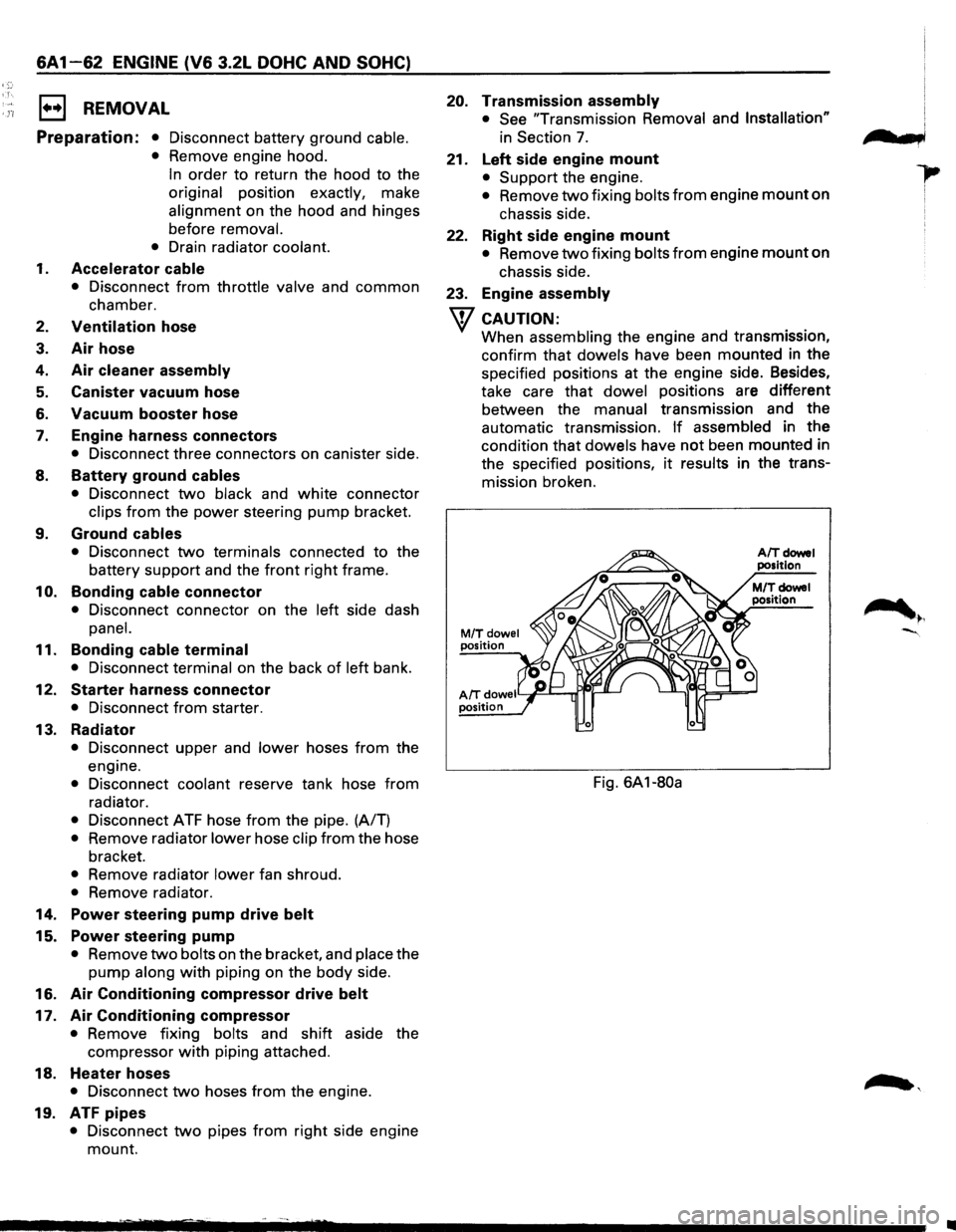
w CAUTION:
When assembling the engine and transmission,
confirm
that dowels have been mounted in the
specified positions at the engine side. Besides,
take care
that dowel positions are different
between the manual transmission and the
automatic transmission.
If assembled in the
condition that dowels have not been mounted in
the specified positions,
it results in the trans
mission broken.
M/Tdowel position
AIT doweiY~--r..ri~-' position
Fig. 6A1-80a
n t b,
•
Page 632 of 1928
68 - 4 ENGINE COOLING
ON-VEHICLE SERVICE
DRAINING AND REFILLING COOLING
SYSTEM
Before draining the cooling system, inspect the sys
tem and perform any necessary service to ensure that
it is clean, does not leak and is in proper working
order. The Engine Coolant (EC) level should be be
tween the "MIN" and "MAX" lines of reserve tank
when the engine is cold. If low, check for leakage and
add
EC up to the "MAX" line. There should not be any
excessive deposit of rust or scales around the radiator
cap
or radiator filler hole, and the EC should also be
free
from oil. Replace the EC if excessively dirty.
1. Completely drain the cooling system by opening
the drain petcock at the bottom of the radiator.
2. Remove the radiator cap.
W WARNING
To avoid the danger of being burned, do not
remove the cap while the engine and radiator
are still hot. Scalding fluid and steam can be
blown out under pressure.
3. Disconnect all hoses from the EC reserve tank.
Scrub and clean the inside of the reserve tank with
soap and water. Flush it well with clean water,
then drain it. Install the reserve tank and hoses.
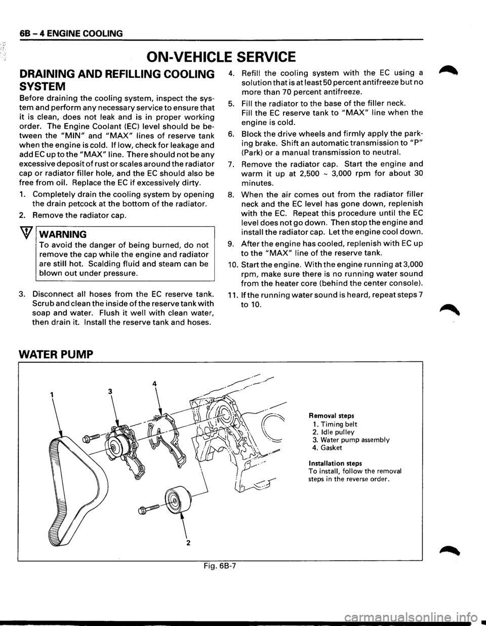
WATER PUMP
3
j
2
4. Refill the cooling system with the EC using a
solution that is at least 50 percent antifreeze but no
more than 70 percent antifreeze.
5. Fill the radiator to the base of the filler neck.
Fill the EC reserve tank to "MAX" line when the
engine is cold.
6. Block the drive wheels and firmly apply the park
ing brake.
Shift an automatic transmission to "P"
(Park) or a manual transmission to neutral.
7. Remove the radiator cap. Start the engine and
warm it up at 2,500 -3,000 rpm for about 30
minutes.
8. When the air comes out from the radiator filler
neck and the EC level has gone down, replenish
with the EC. Repeat this procedure until the EC
level does not go down. Then stop the engine and
install the radiator cap. Let the engine cool down.
9. After the engine has cooled, replenish with EC up
to the "MAX" line of the reserve tank.
10. Start the engine. With the engine running at 3,000
rpm, make sure there is no running water sound
from the heater core (behind the center console).
11. If the running water sound is heard, repeat steps 7
to 10.
Removal steps
1. Timing
belt 2. Idle pulley 3. Water pump assembly
4. Gasket
Installation steps To install, follow the removal steps in the reverse order.
Fig. 6B-7
•
Page 652 of 1928
6C -10 ENGINE FUEL
Adjustment of pedal stroke
Manual Transmission:
• Rotate counterclockwise to loosen the stopper
bolt sufficiently.
• Fully depress the pedal and hold it there hand.
Next, rotate the stopper bolt until it hits the
stopper of pedal bracket. Then, lock the stopper
bolt there.
Automatic Transmission:
• Rotate counterclockwise to loosen the kickdown
switch sufficiently.
• Fully depress the pedal and hold it there hand.
Rotate
the switch clockwise and then rotate
further by 1/2 turn from the position where the
switch clicks. Lock the switch there.
• Step on the accelerator pedal and make sure that
you can hear clicking sound at the full stroke
position.
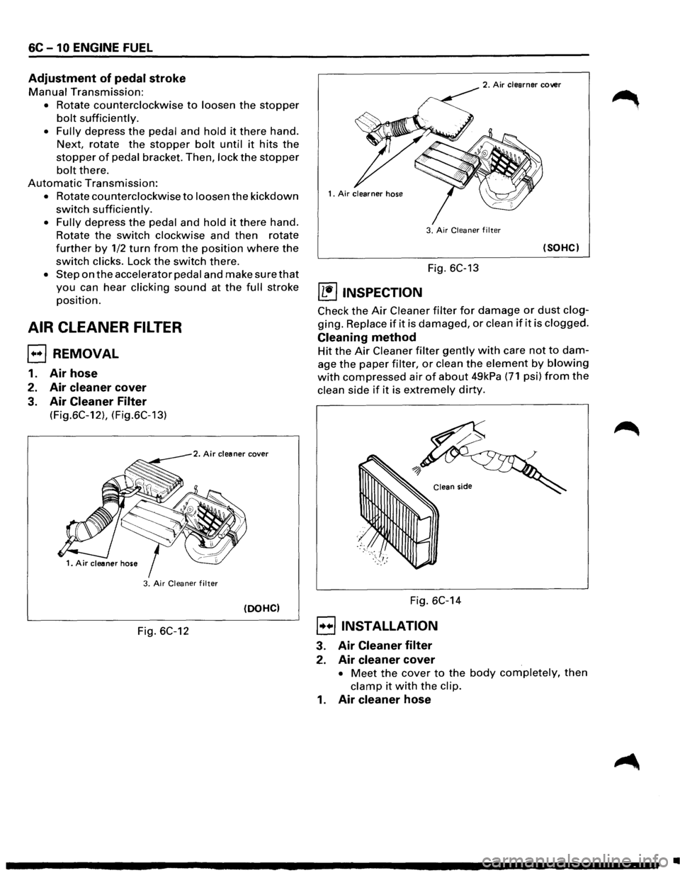
AIR CLEANER FILTER
EJ REMOVAL
1. Air hose
2. Air cleaner cover
3. Air Cleaner Filter
(Fig.6C-12), (Fig.6C-13)
2. Air cleaner cover
3. Air Cleaner filter
(DOHC)
Fig. 6C-12
2. Air clearner cover
3.
Air Cleaner filter
(SOHC)
Fig. 6C-13
~ INSPECTION
Check the Air Cleaner filter for damage or dust clog
ging. Replace if it is damaged, or clean if it is clogged.
Cleaning method
Hit the Air Cleaner filter gently with care not to dam
age the paper filter, or clean the element by blowing
with compressed air of about 49kPa (71 psi) from the
clean side if it is extremely dirty.
Fig. 6C-14
8 INSTALLATION
3. Air Cleaner filter
2. Air cleaner cover
• Meet the cover to the body completely, then
clamp it with the clip.
1. Air cleaner hose
•
Page 657 of 1928
ENGINE ELECTRICAL 601-3
ON-VEHICLE SERVICE
BATTERY CHARGING
Observe the following safety precautions when
charging the battery:
1. Never attempt to charge the battery when the
fluid level is below the lower level line on the
side
of the battery. In this case, the battery
must be replaced.
2. Pay close attention to the battery during the
charging procedure.
Battery charging
should be discontinued or the
rate
of charge reduced if the battery feels hot
to the touch.
Battery charging
should be discontinued or the
rate
of charge reduced if the battery begins to
gas or spew electrolyte from the vent holes.
3. In order to more easily view the hydrometer
blue dot or ring, it may be necessary to jiggle
or tilt the battery.
4. Battery temperature can have a great effect on
battery charging capacity.
5. The sealed battery used on this vehicle may be
either quick-charged or slow-charged in the
same manner
as other batteries.
Whichever method you decide
to use, be sure
that you
completely charge the battery. Never
partially charge the battery.
JUMP STARTING
JUMP STARTING WITH AN AUXILIARY
(BOOSTER)
BATTERY
W CAUTION:
Never push or tow the vehicle in an attempt to
start it.
Serious damage to the emission sys
tem as
well as other vehicle parts will result.
Treat both the discharged battery and the
booster battery
with great care when using
jumper cables. Carefully follow the jump start
ing procedure, being
careful at all times to
avoid sparking.
wwARNING:
Failure to carefully follow the jump starting
procedure
could result in the following:
1. Serious personal injury, particulaly to your
eyes.
2. Property damage from a battery explo
sion, battery acid, or an electrical fire.
3. Damage to the electronic components of
one or both vehicles particularly.
Never expose the battery to an open flame or elec
trical
spark. Gas generated by the battery may catch
fire
or explode.
Remove any rings, watches, or other jewelry before
working around the battery. Protect
your eyes by
wearing
an approved set of goggles.
Never allow battery fluid to come in contact with
your eyes or skin.
Never
allow battery fluid to come in contact with
fabrics or painted surfaces.
Battery
fluid is a highly corrosive acid.
Should battery fluid come in contact with your eyes,
skin, fabric, or a painted surface,
immediately and
thoroughly rinse the affected area with clean tap
water. Never
allow metal tools or jumper cables to come
in contact with the positive battery
terminal, or any
other
metal surface of the vehicle. This will protect
against a short circuit.
Always keep batteries out of the reach of young
children.
JUMP STARTING PROCEDURE
1. Set the vehicle parking brake.
If the vehicle is equipped with an automatic
transmission,
place the selector lever in the
"PARK" position.
If the vehicle is equipped with a manual trans
mission
place the shift lever in the "NEUTRAL"
position.
Turn
"OFF" the ignition.
Turn
"OFF" all lights and any other accessory
requiring
electrical power.
2. Look at the built-in hydrometer.
If the indication area of the built-in hydrometer
is
completely clear, do not try to jump start.
3. Attach the end of one jumper cable to the posi
tive
terminal of the booster battery.
Attach the other end
of the same cable to the
positive
terminal of the discharged battery.
Do not allow the vehicles to touch each other.
This
will cause a ground connection, effectively
neutralizing
the charging procedure.
Be sure that the booster battery has a 12 volt
rating.
4. Attach one end of the remaining cable to the
negative
terminal of the booster battery.
Attach the other end
of the same cable to a
solid engine ground (such as the air condition
ing compressor bracket or the generator
mounting bracket)
of the vehicle with the dis
charged battery.
This ground connection must be at
least 450
mm (18 in) from the battery of the vehicle
whose battery is being charged.
Page 708 of 1928
6E2-12 DRIVEABILITY AND EMISSIONS
L-LITER
A metric unit of capacity.
MALFUNCTION
A problem that causes the system to operate
incorrectly. Typical malfunctions are wiring harness
opens
or shorts, failed sensors or circuit components.
MAP-MANIFOLD ABSOLUTE PRESSURE
Air pressure in the intake manifold with reference to
zero or absolute vacuum.
MPH-MILE PER HOUR
A unit measuring speed needed to travel distance of
one mile (5280 feet) in one hour.
MIT -MANUAL TRANSMISSION
N.C.-NORMALLY CLOSED
State of relay contacts or solenoid plunger is close
when voltage is not applied.
N·m-NEWTON METER (Torque)
A metric unit describing force.
N.M.-NORMALLY OPEN
State of relay contacts or solenoid plung&r' is open
when voltage is applied.
NOx-NITROGEN OXIDES
One of the pullutants found in engirie exhaust.
02-0XYGEN (Sensor)
Monitors the oxygen contel)f of the exhaust system
and generates a
voltage signal to the Engine Control
Module (ECM).
OUTPUT
Result of a functi typically controlled by the ECM.
OXYGEN SE OR
Device that etects the amount of oxygen (02) in the
exhaust
stfeam. /
PCV-~OSITIVE CRANKCASE VENTILATION
Prey£nt fumes in crankcase from passing into
atmosphere.
PNP-PARK/NEUTRAL POSITION
PORT-EXHAUST OR INTAKE PORT
PWM-PULSE WIDTH MODULATE
RPM-REVOLUTION PER MINUTE
A measure of rotational speed.
SELF-DIAGNOSTIC TROl)SLE CODE
The ECM can detect malfunctions in the system. If a
malfunction occurs, the ECM turns on the malfunction
indicator lamp. A OTC can be obtained from the ECM
through the malfunction indicator lamp. This DTC will
indicate the area of the malfunction.
TACH-TACHOMETER
TB-THROTTLE BODY
TBI-THROTTLE BODY FUEL INJECTION
Computer Command Control using throttle body fuel
injection
TP SENSOR-THROTTLE POSITION SENSOR
VACUUM
Negative pressure; less than atmospheric pressure.
VIN-VEHICLE IDENTIFICATION NUMBER
VSS-VEHICLE SPEED SENSOR
Sensor which sends vehicle speed information to the
ECM.
VSV-VACUUM SWITCH VALVE
(Electronically Controlled)
VSV-VACUUM SWITCH VALVE
Temperature controlled vacuum switch, that is used to
route or exhaust vacuum at various engine
temperatures.
WOT -WIDE OPEN THROTTLE
DRIVEABILITV AND EMISSION SECTION SUMMARY
The Driveability and Emissions Sections are sub
divided into three sub sections:
SECTION A: CIRCUIT INFORMATION &
DIAGNOSIS
• Component Locations
• Wiring Diagrams
• ECM Terminal End View and Terminal
Definitions
• On-Board Diagnostic System Check. This
must be the first step of any diagnostic
procedure.
• DTC Charts with facing pages containing
circuit diagrams, circuit operation
information, and
helpful diagnostic
information.
SECTION B: DRIVEABILITY & EMISSIONS
SYMPTONS
• This sub-section assists in diagnosis of
intermittent problems or problems which
don't result in the storing of DTC(s). It is
arranged
by symptoms of poor driveability
and emissions and lists possible causes of
the problems.
SECTION C: COMPONENT CHECKS &
SERVICE
• Component and Circuit Descriptions
• On-Vehicle Service
• Functional
Checks/Diagnostic Charts
•
Page 780 of 1928
6E2-84 DRIVEABILITY AND EMISSIONS
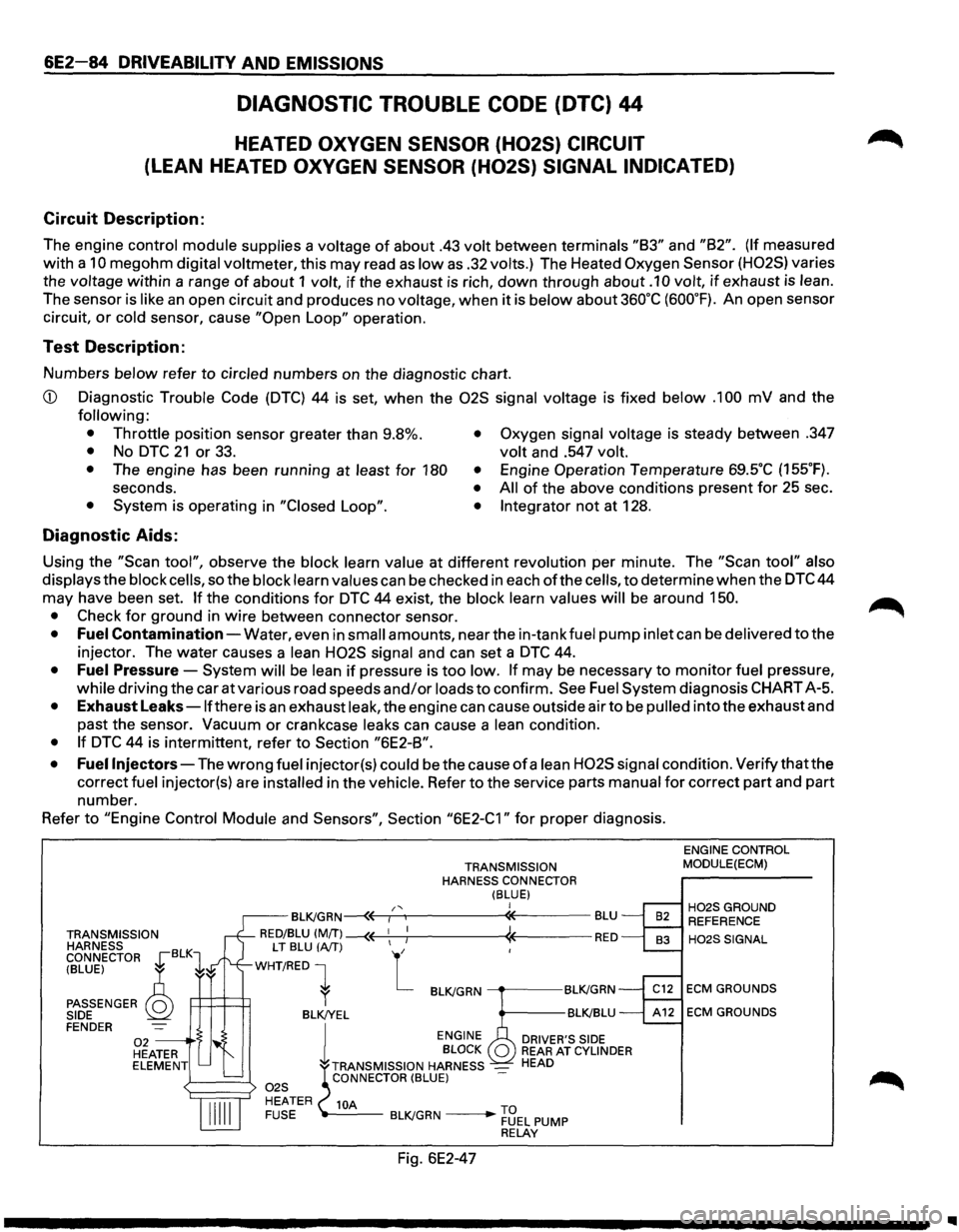
DIAGNOSTIC TROUBLE CODE (DTC) 44
HEATED OXYGEN SENSOR (H02S) CIRCUIT
(LEAN HEATED OXYGEN SENSOR (H02S) SIGNAL INDICATED)
Circuit Description:
The engine control module supplies a voltage of about .43 volt between terminals "83" and "82". (If measured
with a
10 megohm digital voltmeter, this may read as low as .32 volts.) The Heated Oxygen Sensor (H02S) varies
the
voltage within a range of about 1 volt, if the exhaust is rich, down through about .1 0 volt, if exhaust is lean.
The sensor is like an open circuit and produces no voltage, when it is below about 360°C (600°F). An open sensor
circuit,
or cold sensor, cause "Open Loop" operation.
Test Description:
Numbers below refer to circled numbers on the diagnostic chart.
CD Diagnostic Trouble Code (DTC) 44 is set, when the 02S signal voltage is fixed below .1 00 mV and the
following:
• Throttle
position sensor greater than 9.8%.
• No DTC 21 or 33. • Oxygen signal voltage is steady between .347
volt and .547 volt.
•
The engine has been running at least for 180 •
seconds. • • System is operating in "Closed Loop". •
Engine Operation Temperature 69SC (155°F).
All of the above conditions present for 25 sec .
Integrator not at 128 .
Diagnostic Aids:
Using the "Scan tool", observe the block learn value at different revolution per minute. The "Scan tool" also
displays
the block cells, so the block learn values can be checked in each ofthe cells, to determine when the DTC 44
may have been set.
If the conditions for DTC 44 exist, the block learn values will be around 150.
•
Check for ground in wire between connector sensor.
• Fuel Contamination-Water, even in small amounts, near the in-tank fuel pump inlet can be delivered to the
injector. The water causes a
lean H02S signal and can set a DTC 44.
• Fuel Pressure-System will be lean if pressure is too low. If may be necessary to monitor fuel pressure,
while driving the car at various road speeds and/or loads to confirm. See Fuel System diagnosis CHART A-5.
• Exhaust Leaks -lfthere is an exhaust leak, the engine can cause outside air to be pulled into the exhaust and
past the sensor.
Vacuum or crankcase leaks can cause a lean condition.
• If DTC 44 is intermittent, refer to Section "6E2-8".
• Fuel
Injectors-The wrong fuel injector(s) could be the cause of a lean H02S signal condition. Verify that the
correct
fuel injector(s) are installed in the vehicle. Refer to the service parts manual for correct part and part
number.
Refer
to "Engine Control Module and Sensors", Section "6E2-C1" for proper diagnosis.
TRANSMISSION
HARNESS
CONNECTOR
~BLK1
TRANSMISSION
HARNESS CONNECTOR
(BLUE) I /' BL~GRN~r-~----------~-------BLU
RED/BLU (MfT) --(( 1
1 ; « RED
(BLUE) ~
PASSENGER Q SIDE
LT BLU (A/T) L
WHT/RED 1
P:::l=t=t1 l BL~GRN ----.-----BL~GRN
BLK!YEL BL~BLU FENDER 02 --·S HEATER ELEMENT l
ENGINE
DRIVER'S SIDE BLOCK REAR AT CYLINDER
TRANSMISSION HARNESS _ HEAD CONNECTOR (BLUE)
10A -----BL~GRN ____ .,.... ~3EL PUMP RELAY
Fig. 6E2-47
ENGINE CONTROL
MODULE(ECM)
H02SGROUND REFERENCE
H02SSIGNAL
ECM GROUNDS
ECM GROUNDS
..
Page 787 of 1928
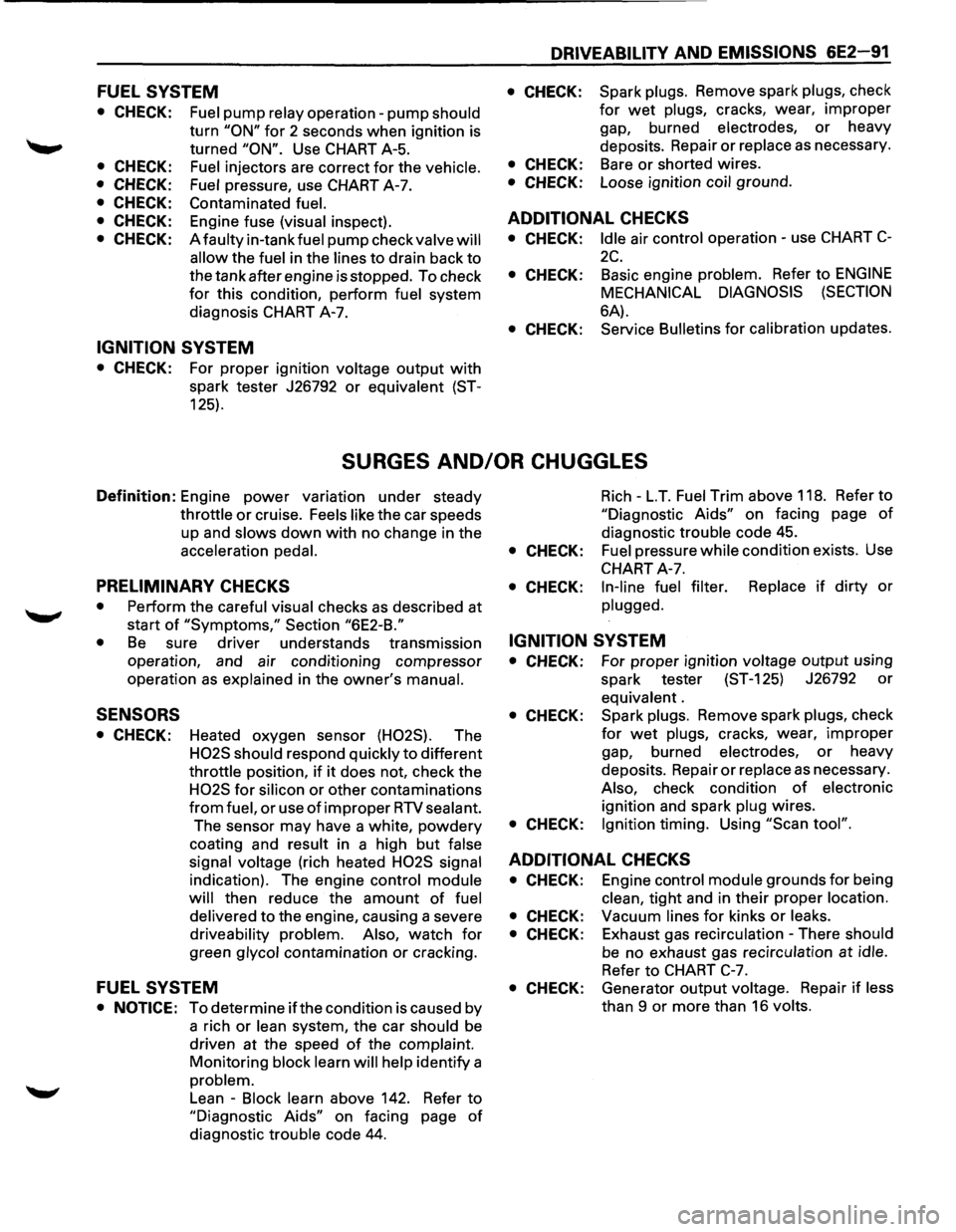
FUEL SYSTEM
• CHECK:
• CHECK:
• CHECK:
• CHECK:
• CHECK:
• CHECK:
Fuel pump relay operation-pump should
turn "ON" for 2 seconds when ignition is
turned
"ON". Use CHART A-5.
Fuel injectors are correct for the vehicle.
Fuel
pressure, use CHART A-7.
Contaminated
fuel.
Engine fuse (visual inspect).
A
faulty in-tank fuel pump check valve will
allow
the fuel in the lines to drain back to
the tank after engine is stopped. To check
for this condition, perform fuel system
diagnosis CHART A-7.
IGNITION SYSTEM
• CHECK: For proper ignition voltage output with
spark tester J26792 or equivalent (ST-
125).
DRIVEABILITY AND EMISSIONS 6E2-91
• CHECK: Spark plugs. Remove spark plugs, check
for wet plugs, cracks, wear, improper
gap, burned electrodes, or heavy
deposits. Repair
or replace as necessary.
• CHECK: Bare or shorted wires.
• CHECK: Loose ignition coil ground.
ADDITIONAL CHECKS
• CHECK: Idle air control operation-use CHART C-
2C.
• CHECK: Basic engine problem. Refer to ENGINE
MECHANICAL DIAGNOSIS (SECTION
6A).
• CHECK: Service Bulletins for calibration updates.
SURGES AND/OR CHUGGLES
Definition: Engine power variation under steady
throttle or cruise. Feels like the car speeds
up and
slows down with no change in the
acceleration pedal.
PRELIMINARY CHECKS
• Perform the careful visual checks as described at
start
of "Symptoms," Section "6E2-B."
•
Be sure driver understands transmission
operation, and air conditioning compressor
operation
as explained in the owner's manual.
SENSORS
• CHECK: Heated oxygen sensor (H02S). The
H02S should respond quickly to different
throttle position, if it does not, check the
H02S for silicon or other contaminations
from fuel, or use of improper RTV sealant.
The sensor may have a white, powdery
coating and result in a high but false
signal voltage
(rich heated H02S signal
indication). The engine control module
will
then reduce the amount of fuel
delivered
to the engine, causing a severe
driveability problem. Also, watch for
green glycol contamination or cracking.
FUEL SYSTEM
• NOTICE: To determine ifthe condition is caused by
a rich
or lean system, the car should be
driven at the speed of the complaint.
Monitoring block learn will help identify a
problem.
Lean -Block learn above 142. Refer to
"Diagnostic Aids" on facing page of
diagnostic trouble code 44.
Rich -L.T. Fuel Trim above 118. Refer to
"Diagnostic Aids" on facing page of
diagnostic trouble code 45.
• CHECK: Fuel pressure while condition exists. Use
CHART A-7.
• CHECK: In-line fuel filter. Replace if dirty or
plugged.
IGNITION SYSTEM
• CHECK: For proper ignition voltage output using
spark tester (ST-125) J26792
or
equivalent .
• CHECK: Spark plugs. Remove spark plugs, check
for wet plugs, cracks, wear, improper
gap, burned electrodes, or heavy
deposits. Repair
or replace as necessary.
Also, check condition of electronic
ignition and spark plug wires.
• CHECK: Ignition timing. Using "Scan tool".
ADDITIONAL CHECKS
• CHECK: Engine control module grounds for being
clean, tight and in their proper location.
• CHECK: Vacuum lines for kinks or leaks.
• CHECK: Exhaust gas recirculation -There should
be no exhaust gas recirculation at idle.
Refer to CHART C-7.
• CHECK: Generator output voltage. Repair if less
than 9 or more than 16 volts.
Page 795 of 1928
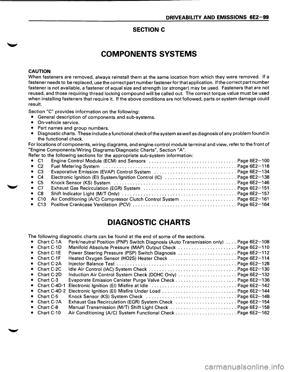
DRIVEABILITV AND EMISSIONS 6E2-99
SECTION C
COMPONENTS SYSTEMS
CAUTION
When fasteners are removed, always reinstall them at the same location from which they were removed. If a
fastener needs
to be replaced, use the correct part number fastener for that application. If the correct part number
fastener is not available, a fastener of equal size and strength (or stronger) may be used. Fasteners that are not
reused, and those requiring thread locking compound will be called out. The correct torque value must be used
when installing fasteners that require it. If the above conditions are not followed, parts or system damage could
result.
Section
"C" provides information on the following:
• General description of components and sub-systems.
• On-vehicle service.
• Part names and group numbers.
• Diagnostic charts. These include a functional check of the system as well as diagnosis of any problem found in
the functional check.
For locations
of components, wiring diagrams, and engine control module terminal and view, refer to the front of
"Engine Components/Wiring Diagrams/Diagnostic Charts", Section "A".
Refer to the following sections for the appropriate sub-system information:
• C1 Engine Control Module (ECM) and Sensors ................................. Page 6E2-1 00
•
C2 Fuel Metering System .................................................. Page 6E2-116
• C3 Evaporative Emission (EVAP) Control System ............................... Page 6E2-134
• C4 Electronic Ignition (EI) System/Ignition Control (IC) ........................... Page 6E2-138
• C5 Knock Sensor (KS) System .............................................. Page 6E2-146
• C7 Exhaust Gas Recirculation (EGR) System ................................... Page 6E2-151
• C8 Shift Indicator Light (M/T Only) ........................................... Page 6E2-157
• C1 0 Air Conditioning (A/C) Compressor Clutch Control System ..................... Page 6E2-161
• C13 Positive Crankcase Ventilation (PCV) ....................................... Page 6E2-164
DIAGNOSTIC CHARTS
The following diagnostic charts can be found at the end of some of the sections.
• Chart C-1A Park/neutral Position (PNP) Switch Diagnosis (Auto Transmission only) .... Page 6E2-108
• Chart C-1 D Manifold Absolute Pressure (MAP) Output Check ...................... Page 6E2-11 0
•
Chart C-1 E Power Steering Pressure (PSP) Switch Diagnosis ...................... Page 6E2-112
• Chart C-1 F Heated Oxygen Sensor (H02S) Heater Check ......................... Page 6E2-114
• Chart C-2A Injector Balance Test ............................................. Page 6E2-128
• Chart C-2C Idle Air Control (lAC) System Check ................................. Page 6E2-130
• Chart C-2D Induction Air Control System Check (DOHC Only) ...................... Page 6E2-132
• Chart C-3 Evaporate Emission Canister Purge Valve Check ....................... Page 6E2-136
• Chart C-4D-1 Electronic Ignition (EI) Misfire at Idle ................................ Page 6E2-142
• Chart C-4D-2 Electronic Ignition (EI) Misfire Under Load ............................ Page 6E2-144
• Chart C-5 Knock Sensor (KS) System Check .................................. Page 6E2-148
• Chart C-7A Exhaust Gas Recirculation (EGR) System Check ....................... Page 6E2-154
• Chart C-8 Manual Transmission (MIT) Shift Light Check ......................... Page 6E2-158
• Chart C-1 0 Air Conditioning (A/C) System Functional Check ....................... Page 6E2-162