change key battery ISUZU TROOPER 1995 Workshop Manual
[x] Cancel search | Manufacturer: ISUZU, Model Year: 1995, Model line: TROOPER, Model: ISUZU TROOPER 1995Pages: 1928
Page 926 of 1928
7A-54 AUTOMATIC TRANSMISSION (4L30-E)
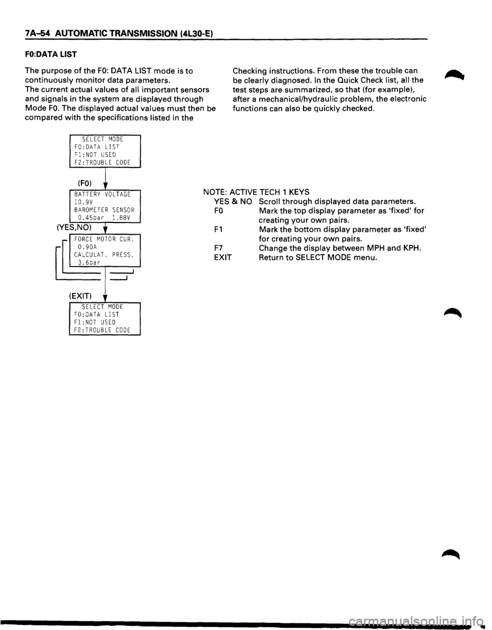
FO:DATA LIST
The purpose of the FO: DATA LIST mode is to
continuously monitor data parameters.
The current actual values
of all important sensors
and signals in the system are displayed
through
Mode FO. The displayed actual values must then be
compared
with the specifications listed in the
SELECT MODE
FO: DATA LIST Fl:NOT USED F2:TROUBLE CODE
(FO) r
Checking instructions. From these the trouble can
be clearly diagnosed.
In the Quick Check list, all the
test steps are summarized, so
that (for example),
after a mechanical/hydraulic problem, the electronic
functions can also be quickly checked.
BATTERY VOLTAGE NOTE: ACTIVE TECH 1 KEYS
10.9V BAROMETER SENSOR 0.45bar 1. 88V
(YES,NO)
' r FORCE MOTOR CUR.
-0.90A CALCULAT. PRESS. 3.6bar
_....J
---'
(EXIT)
SELECT MODE FO:DATA LIST Fl:NOT USED F2:TROUBLE CODE
YES & NO Scroll through displayed data parameters.
FO Mark the top display parameter as 'fixed' for
F1
F7
EXIT
creating your own pairs.
Mark the bottom display parameter as 'fixed'
for creating your own pairs.
Change the display between MPH and
KPH.
Return to SELECT MODE menu.
Page 1465 of 1928
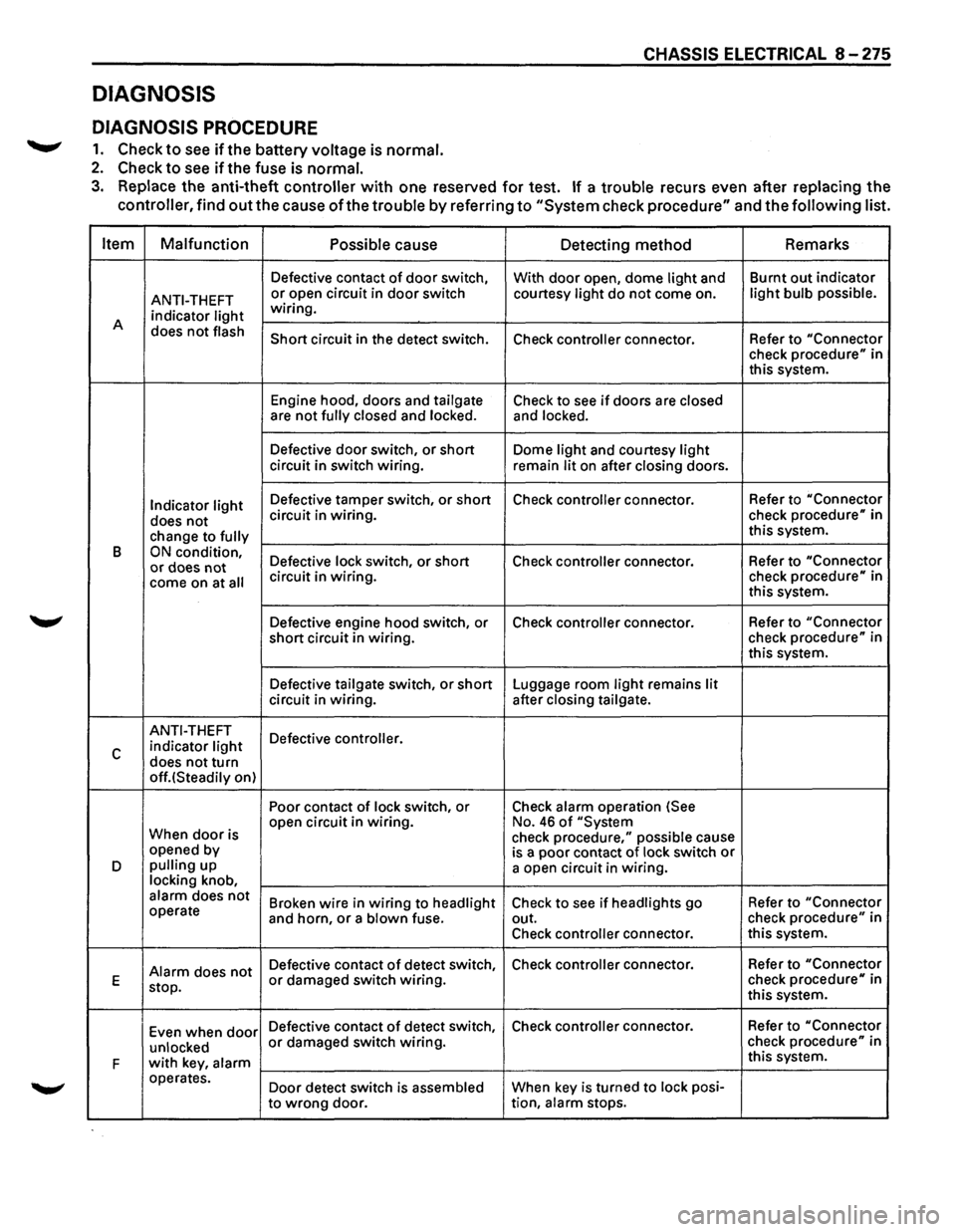
DIAGNOSIS
DIAGNOSIS PROCEDURE
.......,. 1. Check to see ifthe battery voltage is normal.
2. Check to see if the fuse is normal.
CHASSIS ELECTRICAL 8 -275
3. Replace the anti-theft controller with one reserved for test. If a trouble recurs even after replacing the
controller, find
out the cause of the trouble by referring to "System check procedure" and the following list.
Item Malfunction
Possible
cause Detecting method Remarks
Defective
contact of door switch,
With door open, dome light and Burnt
out indicator
ANTI-THEFT or open circuit in door switch courtesy light do not come on. light bulb possible.
indicator light wiring.
A does
not flash Short circuit in the detect switch.
Check controller connector. Refer to "Connector check procedure" in
this system.
Engine hood, doors and
tailgate Check to see if doors are closed are not fully closed and locked. and locked.
Defective door switch, or short Dome light and courtesy light circuit in switch wiring.
remain lit on after closing doors.
Indicator light Defective tamper switch, or short Check controller connector. Refer
to "Connector
does not circuit in wiring. check procedure" in
change to
fully this system.
B
ON condition, Defective lock switch, or short Check controller connector. Refer
to "Connector or does not come on at all circuit in wiring. check procedure" in
this system.
Defective engine hood switch, or Check
controller connector. Refer
to "Connector
short circuit in wiring. check
procedure" in
this system.
Defective
tailgate switch, or short Luggage room light remains lit circuit in wiring. after closing tailgate.
ANTI-THEFT
Defective controller.
c indicator light
does not turn off.(Steadily on) Poor contact
of lock switch, or Check alarm operation (See
When
door is open
circuit in wiring. No. 46 of "System
check procedure," possible cause
opened by
is a poor contact of lock switch or D pulling up
a open circuit in wiring. locking knob, alarm does not Broken wire in wiring to headlight Check to see if headlights go Refer
to "Connector operate
and horn, or a blown fuse. out. check procedure" in
Check
controller connector. this
system.
Alarm does not Defective contact of detect switch, Check controller connector.
Refer to "Connector
E
stop. or damaged switch wiring. check procedure" in
this system.
Even when
door Defective contact of detect switch, Check controller connector. Refer
to "Connector
unlocked
or damaged switch wiring. check procedure" in
F
with key, alarm this system.
operates. Door detect switch is
assembled When key is turned to lock posi-
to
wrong door. tion, alarm stops.
Page 1632 of 1928
9J-8 Supplemental Restraint System
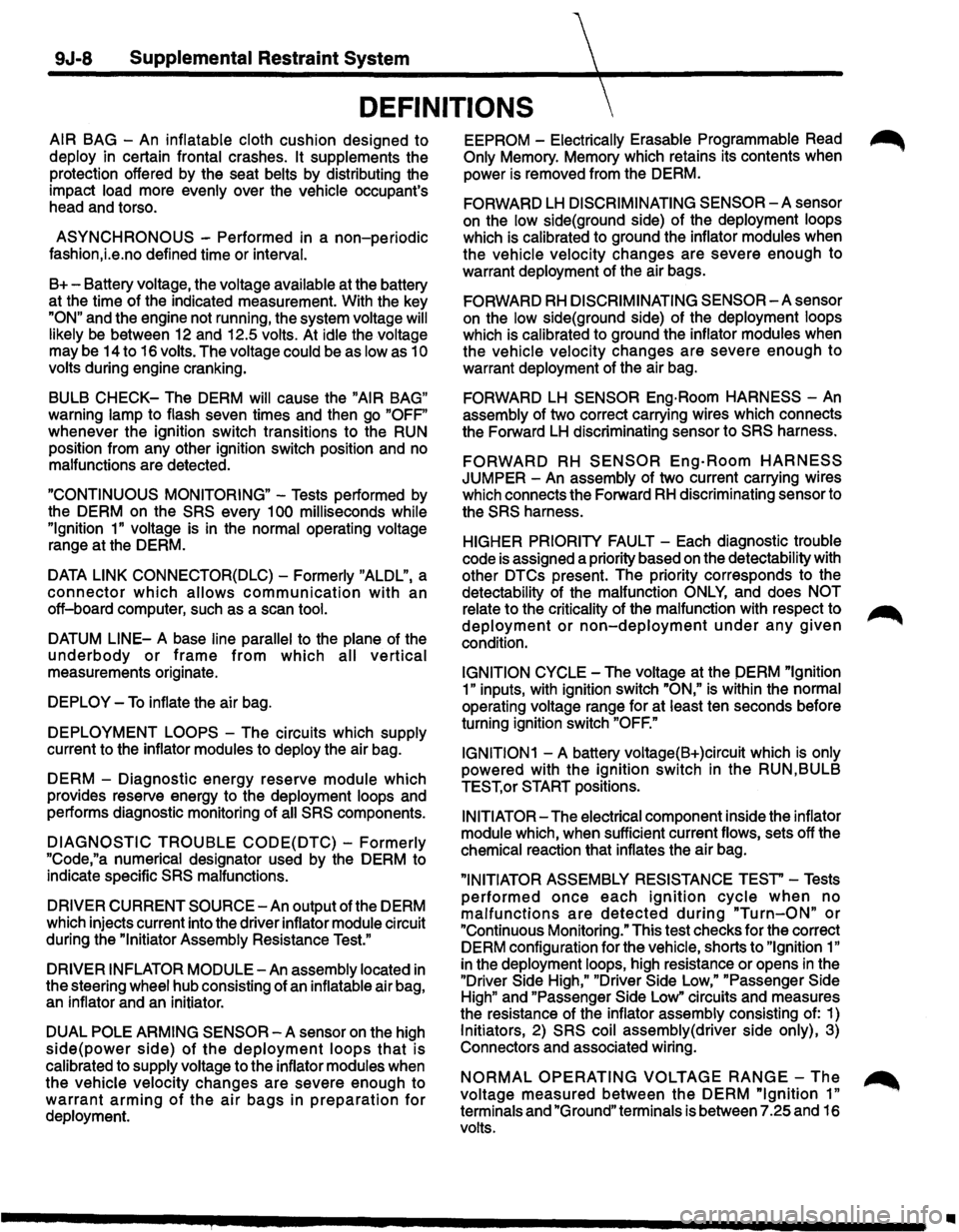
DEFINITIONS
AIR BAG -An inflatable cloth cushion designed to
deploy in certain frontal crashes. It supplements the
protection offered by the seat belts by distributing the
impact load more evenly over the vehicle occupant's
head and torso.
ASYNCHRONOUS -Performed in a non-periodic
fashion,i.e.no defined time or interval.
B+-Battery voltage, the voltage available at the battery
at the time of the indicated measurement. With the key
"ON" and the engine not running, the system voltage will
likely be between 12 and 12.5 volts. At idle the voltage
may be 14 to 16 volts. The voltage could be as low as 1
0
volts during engine cranking.
BULB
CHECK-The DERM will cause the "AIR BAG"
warning lamp to flash seven times and then go "OFF"
whenever the ignition switch transitions to the RUN
position from any other ignition switch position and no
malfunctions are detected.
"CONTINUOUS MONITORING"-Tests performed by
the DERM on the
SRS every 1 00 milliseconds while
"Ignition
1" voltage is in the normal operating voltage
range at the DERM.
DATA LINK CONNECTOR(DLC)-Formerly "ALDL'', a
connector which allows communication with an
off-board computer, such as a scan
tool.
DATUM LINE-A base line parallel to the plane of the
underbody or frame from which all vertical
measurements originate.
DEPLOY-To inflate the air bag.
DEPLOYMENT
LOOPS - The circuits which supply
current to the inflator modules to deploy the air bag.
DERM -Diagnostic
energy reserve module which
provides reserve energy to the deployment loops and
performs diagnostic monitoring of
all SRS components.
DIAGNOSTIC TROUBLE CODE(DTC) -Formerly
"Code,"a numerical designator used by the DERM to
indicate specific
SRS malfunctions.
DRIVER CURRENT SOURCE-An output of the DERM
which injects current into the driver inflator module circuit
during the "Initiator Assembly Resistance
Test."
DRIVER INFLATOR
MODULE-An assembly located in
the steering wheel hub consisting of an inflatable air bag,
an inflator and an initiator.
DUAL
POLE ARMING SENSOR-A sensor on the high
side(power side) of the deployment loops that is
calibrated to supply voltage to the inflator modules when
the vehicle velocity changes are severe enough to
warrant arming of the air bags in preparation for
deployment.
EEPROM -Electrically Erasable Programmable Read ~
Only Memory. Memory which retains its contents when
power
is removed from the DERM.
FORWARD LH DISCRIMINATING SENSOR-A sensor
on the low side(ground side) of the deployment loops
which is calibrated to ground the inflator modules when
the vehicle velocity changes are severe enough to
warrant deployment of the air bags.
FORWARD RH DISCRIMINATING SENSOR-A sensor
on the low side(ground side) of the deployment loops
which
is calibrated to ground the inflator modules when
the vehicle velocity changes are severe enough
to
warrant deployment of the air bag.
FORWARD LH SENSOR Eng-Room HARNESS-An
assembly of two correct carrying wires which connects
the Forward
LH discriminating sensor to SRS harness.
FORWARD RH SENSOR Eng-Room HARNESS
JUMPER-An assembly of two current carrying wires
which connects the Forward
RH discriminating sensor to
the
SRS harness.
HIGHER PRIORITY FAULT-Each diagnostic trouble
code
is assigned a priority based on the detectability with
other DTCs present. The priority corresponds to the
detectability of the malfunction ONLY, and does NOT
relate to the criticality of the malfunction with respect to ~
deployment or non-deployment under any given
condition.
IGNITION CYCLE -The voltage at the PERM "Ignition
1"
inputs, with ignition switch "ON," is within the normal
operating voltage range for at least ten seconds before
turning ignition switch
"OFF."
IGNITION1
-A battery voltage(B+)circuit which is only
powered with the ignition switch in the RUN,BULB
TEST,or START positions.
INITIATOR-The electrical component inside the inflator
module which, when sufficient current flows, sets off the
chemical reaction that inflates the air bag.
"INITIATOR ASSEMBLY RESISTANCE TEST"-Tests
performed once each ignition cycle when no
malfunctions are detected during "Turn-ON" or
"Continuous Monitoring." This test checks for the correct
DERM configuration for the vehicle, shorts to
"Ignition 1"
in the deployment loops, high resistance or opens in the
"Driver
Side High," "Driver Side Low," "Passenger Side
High"
and "Passenger Side Low" circuits and measures
the resistance of the inflator assembly consisting of: 1)
Initiators, 2) SRS coil assembly(driver side only), 3)
Connectors and associated wiring.
NORMAL OPERATING VOLTAGE RANGE-The ~
voltage measured between the DERM "Ignition 1" ·
terminals and "Ground" terminals is between 7.25 and 16
volts.
•