oil change ISUZU TROOPER 1995 User Guide
[x] Cancel search | Manufacturer: ISUZU, Model Year: 1995, Model line: TROOPER, Model: ISUZU TROOPER 1995Pages: 1928
Page 433 of 1928
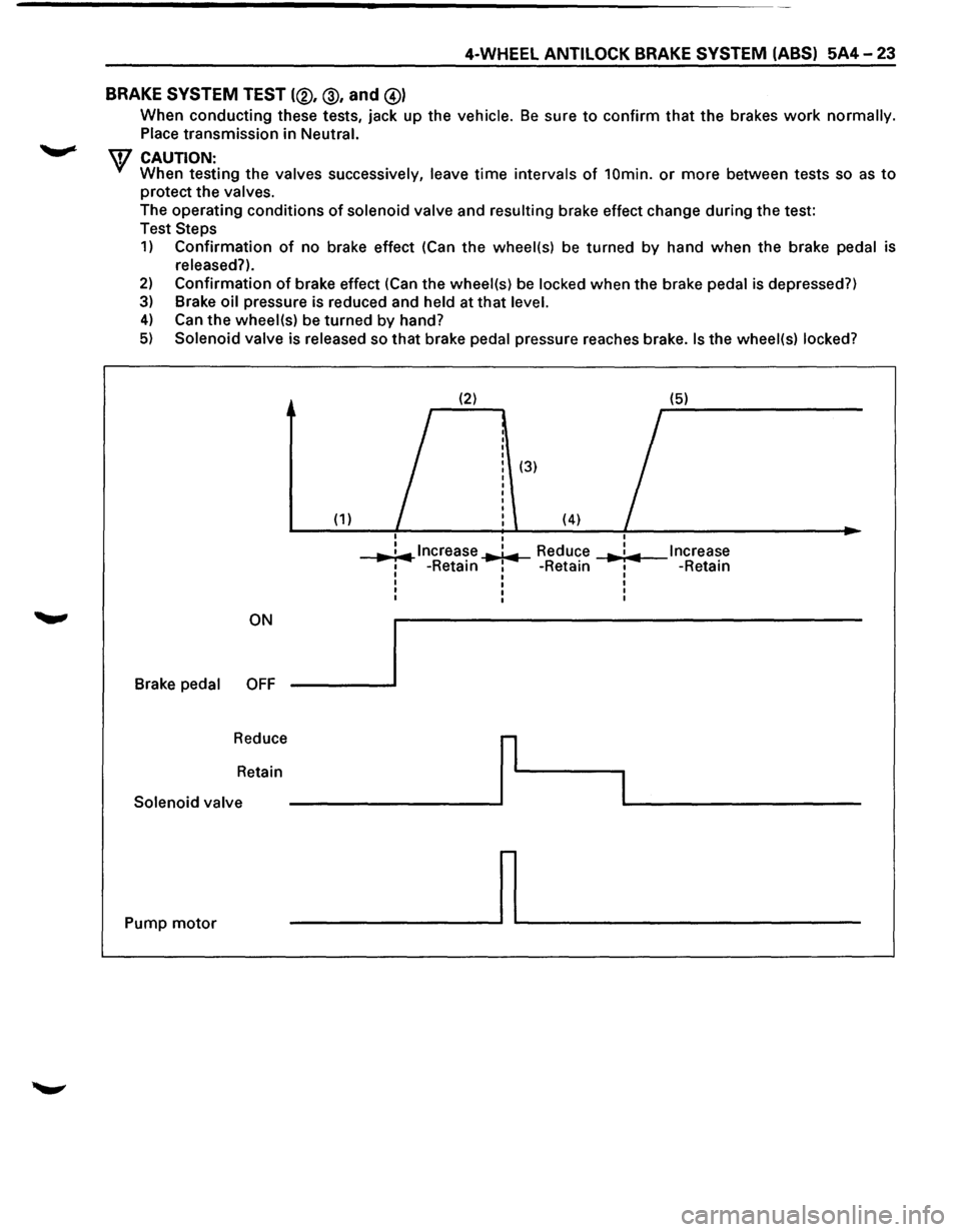
4-WHEEL ANTILOCK BRAKE SYSTEM (ABS) 5A4-23
BRAKE
SYSTEM TEST (®, @, and @)
When conducting these tests, jack up the vehicle. Be sure to confirm that the brakes work normally.
Place transmission
in Neutral.
\V CAUTION: When testing the valves successively, leave time intervals of 10min. or more between tests so as to
protect the valves.
The operating conditions
of solenoid valve and resulting brake effect change during the test:
Test
Steps
1) Confirmation of no brake effect (Can the wheel(s) be turned by hand when the brake pedal is
released?).
2) Confirmation of brake effect (Can the wheel(s) be locked when the brake pedal is depressed?)
3) Brake oil pressure is reduced and held at that level.
4) Can the wheel(s) be turned by hand?
5) Solenoid valve is released so that brake pedal pressure reaches brake. Is the wheel(s) locked?
(2) (5)
I
(3)
(1) (4) I
I
..,. ;.,.. lncrea~e ..,.1.,.. Reduce I Increase ... : ... 1 -Retam 1 -Retain I -Retain I I I
I I I
I I I
I I I
ON
Brake
pedal OFF
Reduce
r
Retain
I Solenoid valve
Pump
motor ~
Page 507 of 1928
ENGINE DIAGNOSIS 6-9
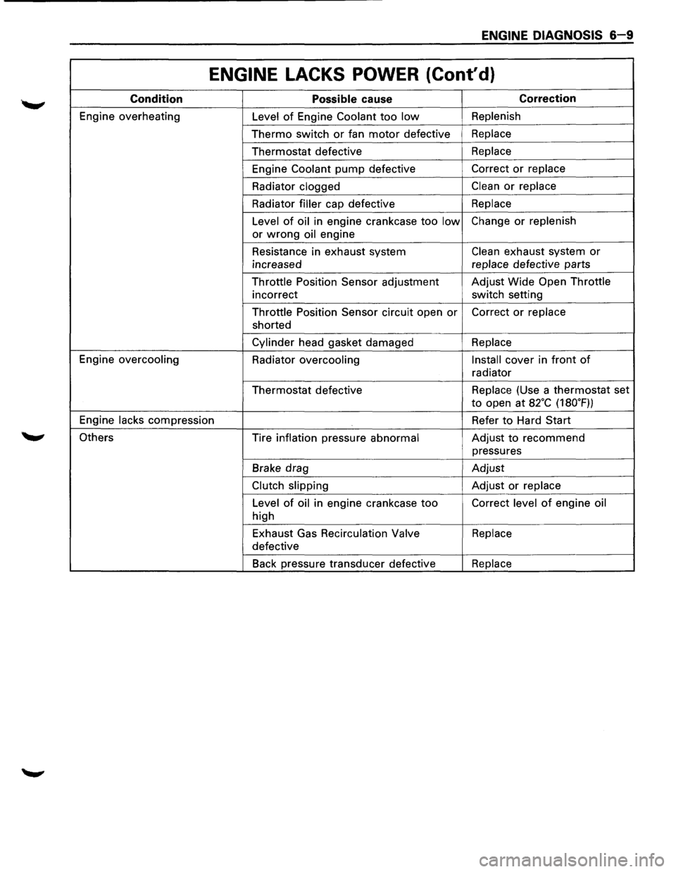
ENGINE LACKS POWER (Cont'd)
Condition Possible cause Correction
Engine overheating
Level of Engine Coolant too low Replenish
Thermo switch or fan motor defective Replace
Thermostat defective Replace
Engine
Coolant pump defective Correct or replace
Radiator clogged
Clean or replace
Radiator
filler cap defective Replace
Level
of oil in engine crankcase too low Change or replenish
or
wrong oil engine
Resistance in exhaust system
Clean exhaust system or
increased replace
defective parts
Throttle Position Sensor adjustment Adjust
Wide Open Throttle
incorrect switch setting
Throttle Position Sensor circuit open
or Correct or replace
shorted
Cylinder head gasket damaged Replace
Engine overcooling
Radiator
overcooling Install cover
in front of
radiator
Thermostat defective Replace
(Use a thermostat set
to open at a2·c (180.F))
Engine
lacks compression Refer to Hard Start
Others Tire inflation pressure
abnormal Adjust to recommend
pressures
Brake drag Adjust
Clutch slipping Adjust or replace
Level
of oil in engine crankcase too Correct level of engine oil
high
Exhaust Gas
Recirculation Valve Replace
defective
Back pressure transducer defective
Replace
Page 508 of 1928
6-10 ENGINE DIAGNOSIS
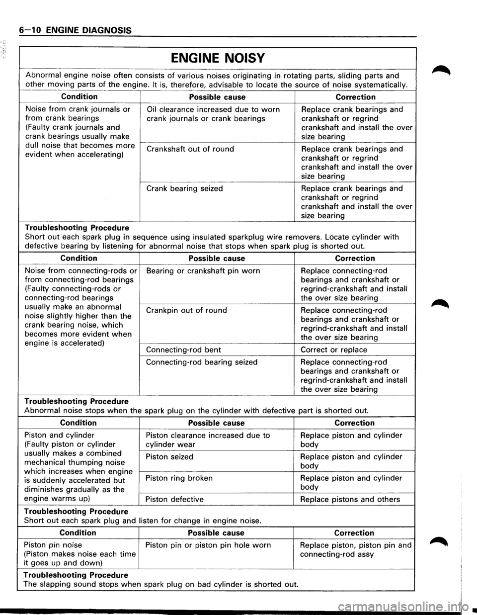
ENGINE
NOISY
Abnormal engine noise often consists of various noises originating in rotating parts, sliding parts and
other moving parts
of the engine. It is, therefore, advisable to locate the source of noise systematically.
Condition
Possible cause Correction
Noise from crank journals or Oil clearance increased due to worn Replace crank bearings and
from crank bearings
crank journals
or crank bearings crankshaft or regrind
(Faulty crank journals and
crankshaft and
install the over
crank bearings
usually make
size bearing
dull noise that becomes more Crankshaft out of round
Replace crank bearings and
evident when accelerating)
crankshaft
or regrind
crankshaft and
install the over
size bearing
Crank bearing seized Replace crank bearings and
crankshaft or regrind
crankshaft and
install the over
size bearing
Troubleshooting Procedure
Short out each spark plug in sequence using insulated sparkplug wire removers. Locate cylinder with
defective bearing by listening for abnormal noise that stops when spark plug is shorted out.
Condition
Possible cause Correction
Noise from connecting-rods or Bearing or crankshaft pin worn Replace connecting-rod
from connecting-rod bearings
bearings and crankshaft or
(Faulty connecting-rods or regrind-crankshaft and install
connecting-rod bearings
the over size bearing
usually make an abnormal
Crankpin out of round Replace
connecting-rod
noise slightly higher than the
bearings and crankshaft
or crank bearing noise, which regrind-crankshaft and install becomes more evident when the over size bearing
engine is accelerated)
Connecting-rod bent
Correct or replace
Connecting-rod bearing seized Replace
connecting-rod
bearings and crankshaft
or
regrind-crankshaft and install
the over size bearing
Troubleshooting Procedure
Abnormal noise stops when the spark plug on the cylinder with defective part is shorted out.
Condition
Possible cause Correction
Piston and cylinder Piston clearance increased due to Replace piston and cylinder
(Faulty piston or cylinder
cylinder
wear body
usually makes a combined Piston seized Replace piston and cylinder
mechanical thumping noise body which increases when engine Piston ring broken Replace piston and cylinder
is suddenly accelerated but
diminishes gradually as the body
engine warms up) Piston defective Replace pistons and others
Troubleshooting Procedure
Short out each spark plug and listen for change in engine noise.
Condition
Possible cause Correction
Piston pin noise Piston pin or piston pin hole worn Replace piston, piston pin and
(Piston makes noise each time connecting-rod assy
it goes up and down)
Troubleshooting Procedure
The slapping sound stops when spark plug on bad cylinder is shorted out.
•
Page 514 of 1928
6-16 ENGINE DIAGNOSIS
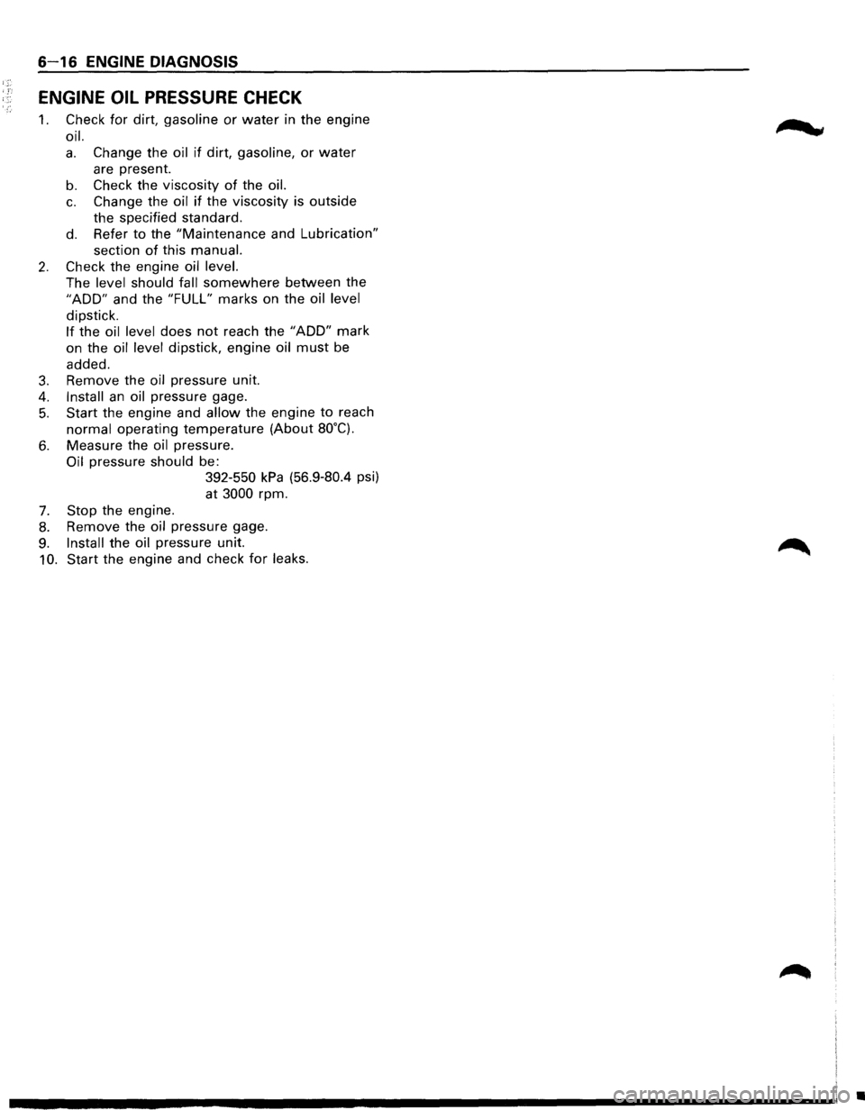
ENGINE OIL PRESSURE CHECK
1. Check for dirt, gasoline or water in the engine
oil.
a. Change the oil if dirt, gasoline, or water
are present.
b. Check the viscosity of the oil.
c. Change the oil if the viscosity is outside
the specified standard.
d. Refer to the "Maintenance and Lubrication"
section of this manual.
2. Check the engine oil level.
The level should fall somewhere between the
"ADD" and the "FULL" marks on the oil level
dipstick.
If the oil level does not reach the "ADD" mark
on the
oil level dipstick, engine oil must be
added.
3. Remove the oil pressure unit.
4. Install an oil pressure gage.
5. Start the engine and allow the engine to reach
normal operating temperature (About 80°C).
6. Measure the oil pressure.
Oil pressure should be:
7. Stop the engine.
392-550 kPa (56.9-80.4 psi)
at
3000 rpm.
8. Remove the oil pressure gage.
9. Install the oil pressure unit.
10. Start the engine and check for leaks.
m ... cw
•
Page 550 of 1928
6A-34 GENERAL ENGINE MECHANICAL
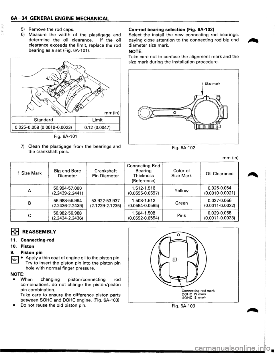
5) Remove the rod caps.
6) Measure the width of the plastigage and
determine the
oil clearance. If the oil
clearance
exceeds the limit, replace the rod
bearing
as a set (Fig. 6A-101).
mm(in)
Standard Limit
0.025-0.058
(0.001 0-0.0023) 0.12 (0.0047)
Fig. 6A-101
7) Clean the plastigage from the bearings and
the crankshaft pins.
1
Size Mark Big
end Bore
Diameter
A 56.994-57.000
(2.2439-2.2441)
B 56.988-56.994
(2.2436-2.2439)
c 56.982-56.988
(2.2434-2.2436)
1,.!•1 REASSEMBLY
11. Connecting-rod
10. Piston
9. Piston pin
Crankshaft
Pin Diameter
53.922-53.937
(2.1229-2.1235)
D • Apply a thin coat of engine oil to the piston pin.
r..::::J Try to insert the piston pin into the piston pin
hole with normal finger pressure.
NOTE:
•
When changing piston/connecting rod
combinations,
do not change the piston/piston
pin combination.
Take care
to ensure the difference piston parts
between
SOHC and DOHC engine. (Fig. 6A-1 03)
• Do not reuse the old piston pin.
Con-rod bearing selection (Fig. GA-1 02)
Select the install the new connecting rod bearings,
paying
close attention to the connecting rod big end
diameter size mark.
NOTE:
Take care not to confuse the alignment mark and the
size mark during the
installation procedure.
Connecting Rod
Bearing
Thickness
(Reference)
1.512-1.516
(0.0595-0.0597)
1.508-1.512
(0.0594-0.0595)
1.504-1.508
(0.0592-0.0594)
1 Size mark
Fig. 6A-1 02
mm (in)
Color of Oil Clearance
Size Mark
Yellow 0.025-0.054 (0.001 0-0.0021)
Green 0.027-0.056
(0.0011-0.0022)
Pink 0.029-0.058
(0.0011-0.0023)
Connecting rod mark DOHC W mark SOHC S mark
Fig. 6A-103
•
Page 631 of 1928
Mixing ratio(%) 0 10 20 30 40 50
~
' -10
'
1
' -30
~ -40
In case of 8.5 lit total cooling system capacity
Mixing Anti-freeze
Water: solution: ratio (%) lit. (U.S. gal) lit. (U.S. gal.)
0 0 0
8.5 (2.2) 10 0.9 (0.3) 7.6 (2.0) 15
1.3 (0.4) 7.2 (1.9) 20 1.7 (0.5) 6.8 (1.8)
25 2.1 (0.6) 6.4 (1.7) 30 2.6 (0.7) 5.9 (1.6)
35 3.0 (0.8) 5.5
(1.5) 40 3.4 (0.9) 5.1 (1.3)
45 3.8 (1.0) 4.7 (1.2) 50 4.3 (1.1)
4.2 (1.1)
Fig. 68-5
ENGINE COOLING 68-3
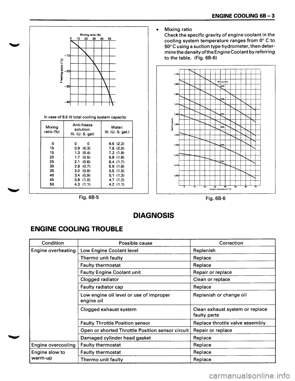
• Mixing ratio
Check
the specific gravity of engine coolant in the
cooling system temperature ranges from oo C to
50° C using a suction type hydrometer, then deter
mine the densityofthe Engine Coolant by referring
to the table. (Fig. 68-6)
1,100 1'-........ ........ ...... .............. Mixing ratio
~"""--r-... 1'-""' 1,1)90
........ ...... ........ ........ .......... '
1,000
'"" 1,07 o......_ 1'-........ I'-.......... I"-........ .......
I"-........ ..........
................. I"-........
'
1,080
....... I"-........ ~ ........ ......
........ "'" ~"""--r--..... 1,050
r-. ........ ~ .......... ......
---
........ ........ 1,040
r-.... !'--.. 1'-0 '"" ~"""--1'-.... ........ 1,03
1--....... ........ r--~ ........
'
1,020
....... ~ 1'-0 ~"""---.... 1,01
...... ,
'
1,000
10 20 30 40 50 60 70 Coolant temperature ("C)
Fig. 68-6
DIAGNOSIS
ENGINE COOLING TROUBLE
Condition Possible cause Correction
Engine
overheating Low Engine Coolant level Replenish
Thermo unit faulty Replace
Faulty
thermostat Replace
Faulty
Engine Coolant unit Repair or replace
Clogged
radiator Clean or replace
Faulty
radiator cap Replace
Low engine oil level or use of improper Replenish or change oil
engine oil
Clogged exhaust system Clean exhaust system or replace
faulty parts
Faulty Throttle Position sensor Replace throttle valve assembly
Open or shorted Throttle Position sensor circuit Repair or replace
Damaged cylinder head gasket Replace
Engine overcooling Faulty thermostat Replace
Engine slow to Faulty thermostat Replace
warm-up Thermo unit faulty Replace
Page 637 of 1928
E!) INSTALLATION
6. Radiator assembly
• Install cushion rubbers on both sides of radia
tor bottom.
• Install radiator assembly with hose, taking
care
not to damage the radiator core with a fan
blade.
5. Bracket
• Support the radiator uppertankwith the bracket
and secure the radiator.
4. Reserve tank hose
3. Fan guide, lower
2. Radiator hose
• Connect inlet hose and outlet hose to the
engine.
1. Oil cooler hose (A/T)
• Connect oil cooler hose for automatic trans-
mission.
• Connect battery ground cable.
• Pour engine coolant.
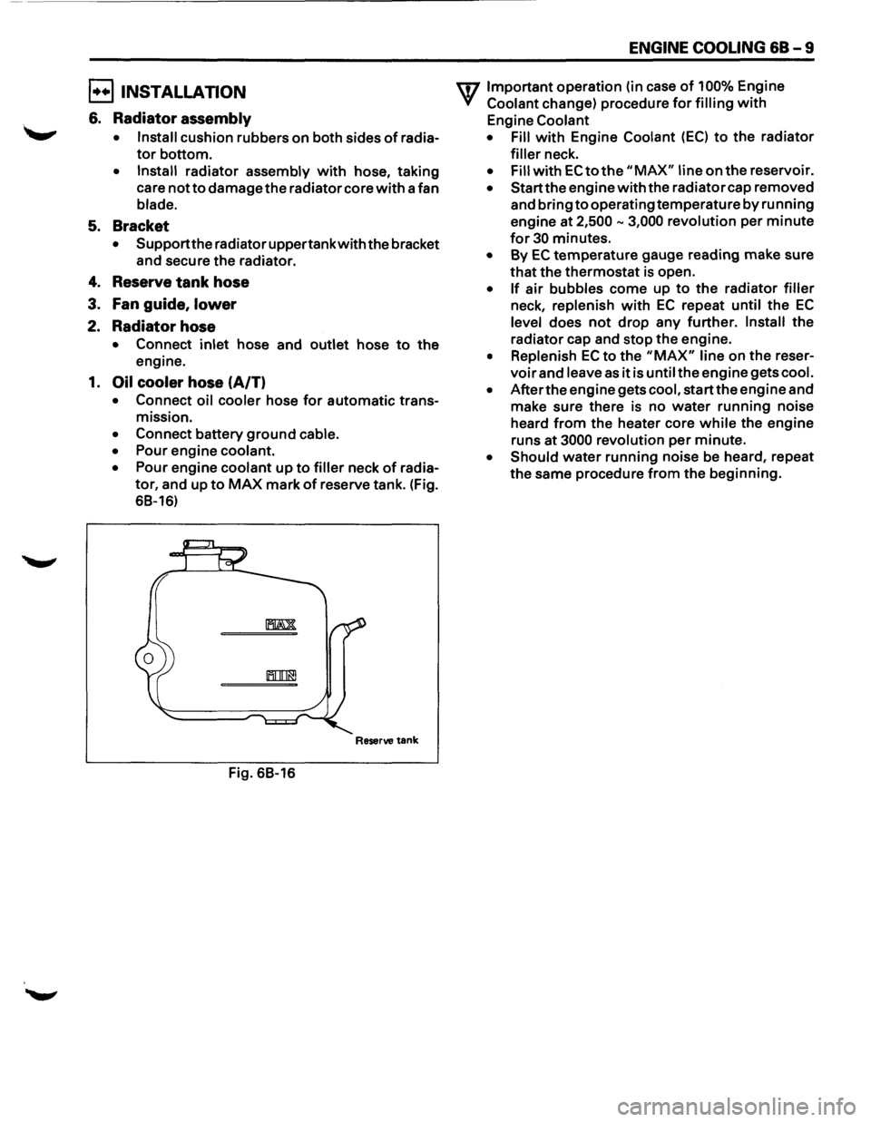
• Pour engine coolant up to filler neck of radia
tor, and up to MAX mark of reserve tank. (Fig.
68-16)
Reserve tank
Fig. 68-16
ENGINE COOLING 68-9
U7 Important operation (in case of 100% Engine
V Coolant change) procedure for filling with
Engine Coolant
• Fill
with Engine Coolant (EC) to the radiator
filler neck.
• Fill with EC to the "MAX" line on the reservoir.
• Start the engine with the radiator cap removed
and bring
to operating temperature by running
engine at
2,500-3,000 revolution per minute
for 30 minutes.
• By EC temperature gauge reading make sure
that the thermostat is open.
• If air bubbles come up to the radiator filler
neck, replenish with EC repeat until the EC
level does not drop any further. Install the
radiator cap and stop the engine.
• Replenish EC to the "MAX" line on the reser
voir and leave as it is until the engine gets cool.
• After the engine gets cool, start the engine and
make sure there is no
water running noise
heard
from the heater core while the engine
runs
at 3000 revolution per minute.
• Should water running noise be heard, repeat
the same procedure from the beginning.
Page 742 of 1928
6E2-46 DRIVEABILITV AND EMISSIONS
CHART A-3
(Page 3 of 3)
ENGINE CRANKS BUT WILL NOT RUN
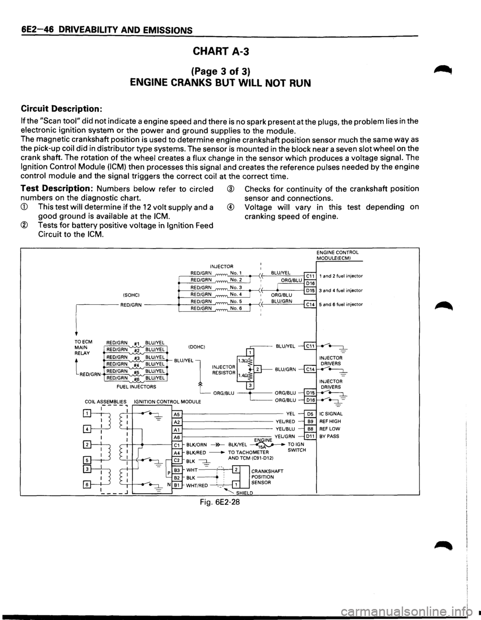
Circuit Description:
If the "Scan tool" did not indicate a engine speed and there is no spark present at the plugs, the problem lies in the
electronic ignition system
or the power and ground supplies to the module.
The magnetic crankshaft position is used to determine engine crankshaft position sensor much the same way as
the pick-up coil did in distributor type systems. The sensor is mounted in the block near a seven slot wheel on the
crank shaft. The rotation
of the wheel creates a flux change in the sensor which produces a voltage signal. The
Ignition Control Module (ICM) then processes this signal and creates the reference pulses needed by the engine
control module and the signal triggers the correct coil at the correct time.
Test Description: Numbers below refer to circled ® Checks for continuity of the crankshaft position
numbers on the diagnostic chart. sensor and connections.
available at the ICM. cranking speed of engine.
® Tests for battery positive voltage in Ignition Feed
Circuit to the
ICM.
TO ECM RED/GRN #1 BLU/YEL MAIN RELAY
tRED/GRN
RED/GRN #2 BLU/YEL
RED/GRN #3 BLU/YEL
RED/GRN '"#4 BLU/YEL RED/GRN #5 BLU/YEL RED/GRN #6 BLU/YEL
FUEL
INJECTORS INJECTOR
RED/GRN RED/GRN RED/GRN
E"'QINE YELJGRN D11 BLK!ORN ----)>--BLK!YEL _____..,-~ TO IGN BLK!RED
-TO TACHOMETER SWITCH BLK --:::J_ AND TCM (C91-D12)
WHT2cl]= :-·-, 2 CRANKSHAFT BLK ~ : POSITION WHT/RED · __ ,' 1 SENSOR
'-;SHIELD
Fig. 6E2-28
ENGINE CONTROL
MODULEIECM)
1 and 2 fuel injector
•
Page 787 of 1928
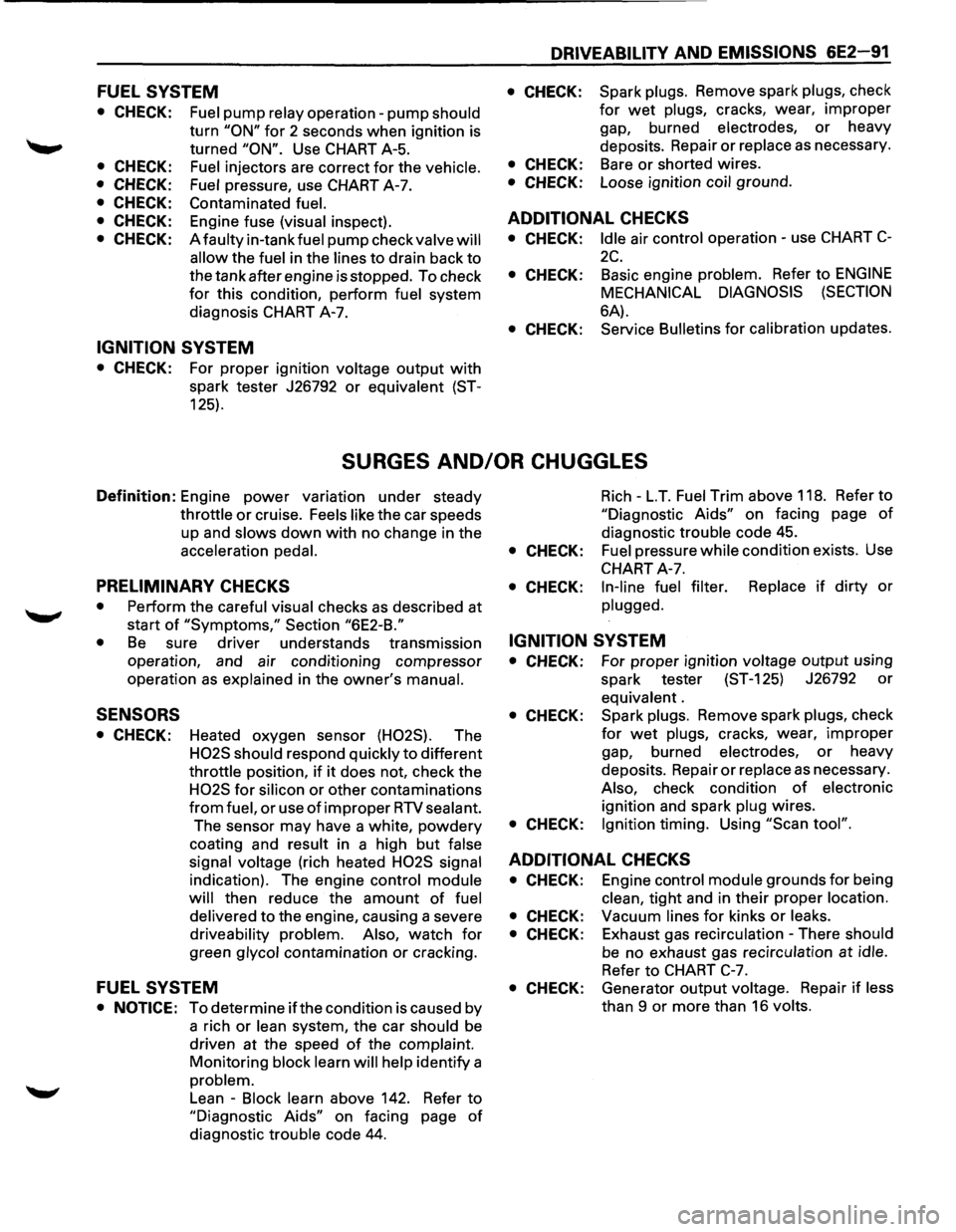
FUEL SYSTEM
• CHECK:
• CHECK:
• CHECK:
• CHECK:
• CHECK:
• CHECK:
Fuel pump relay operation-pump should
turn "ON" for 2 seconds when ignition is
turned
"ON". Use CHART A-5.
Fuel injectors are correct for the vehicle.
Fuel
pressure, use CHART A-7.
Contaminated
fuel.
Engine fuse (visual inspect).
A
faulty in-tank fuel pump check valve will
allow
the fuel in the lines to drain back to
the tank after engine is stopped. To check
for this condition, perform fuel system
diagnosis CHART A-7.
IGNITION SYSTEM
• CHECK: For proper ignition voltage output with
spark tester J26792 or equivalent (ST-
125).
DRIVEABILITY AND EMISSIONS 6E2-91
• CHECK: Spark plugs. Remove spark plugs, check
for wet plugs, cracks, wear, improper
gap, burned electrodes, or heavy
deposits. Repair
or replace as necessary.
• CHECK: Bare or shorted wires.
• CHECK: Loose ignition coil ground.
ADDITIONAL CHECKS
• CHECK: Idle air control operation-use CHART C-
2C.
• CHECK: Basic engine problem. Refer to ENGINE
MECHANICAL DIAGNOSIS (SECTION
6A).
• CHECK: Service Bulletins for calibration updates.
SURGES AND/OR CHUGGLES
Definition: Engine power variation under steady
throttle or cruise. Feels like the car speeds
up and
slows down with no change in the
acceleration pedal.
PRELIMINARY CHECKS
• Perform the careful visual checks as described at
start
of "Symptoms," Section "6E2-B."
•
Be sure driver understands transmission
operation, and air conditioning compressor
operation
as explained in the owner's manual.
SENSORS
• CHECK: Heated oxygen sensor (H02S). The
H02S should respond quickly to different
throttle position, if it does not, check the
H02S for silicon or other contaminations
from fuel, or use of improper RTV sealant.
The sensor may have a white, powdery
coating and result in a high but false
signal voltage
(rich heated H02S signal
indication). The engine control module
will
then reduce the amount of fuel
delivered
to the engine, causing a severe
driveability problem. Also, watch for
green glycol contamination or cracking.
FUEL SYSTEM
• NOTICE: To determine ifthe condition is caused by
a rich
or lean system, the car should be
driven at the speed of the complaint.
Monitoring block learn will help identify a
problem.
Lean -Block learn above 142. Refer to
"Diagnostic Aids" on facing page of
diagnostic trouble code 44.
Rich -L.T. Fuel Trim above 118. Refer to
"Diagnostic Aids" on facing page of
diagnostic trouble code 45.
• CHECK: Fuel pressure while condition exists. Use
CHART A-7.
• CHECK: In-line fuel filter. Replace if dirty or
plugged.
IGNITION SYSTEM
• CHECK: For proper ignition voltage output using
spark tester (ST-125) J26792
or
equivalent .
• CHECK: Spark plugs. Remove spark plugs, check
for wet plugs, cracks, wear, improper
gap, burned electrodes, or heavy
deposits. Repair
or replace as necessary.
Also, check condition of electronic
ignition and spark plug wires.
• CHECK: Ignition timing. Using "Scan tool".
ADDITIONAL CHECKS
• CHECK: Engine control module grounds for being
clean, tight and in their proper location.
• CHECK: Vacuum lines for kinks or leaks.
• CHECK: Exhaust gas recirculation -There should
be no exhaust gas recirculation at idle.
Refer to CHART C-7.
• CHECK: Generator output voltage. Repair if less
than 9 or more than 16 volts.
Page 788 of 1928
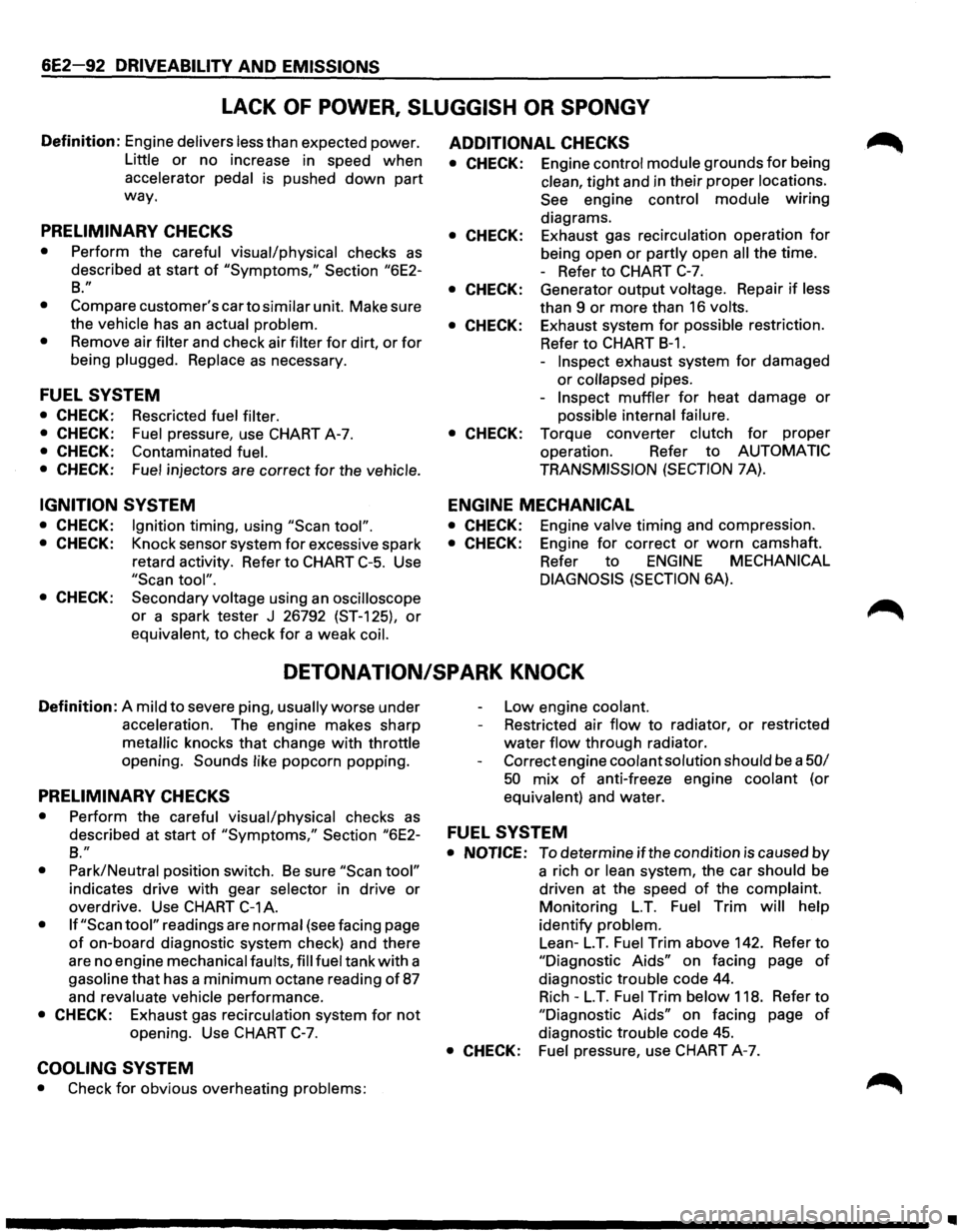
6E2-92 DRIVEABILITY AND EMISSIONS
LACK OF POWER, SLUGGISH OR SPONGY
Definition: Engine delivers less than expected power.
Little or no increase in speed when
accelerator
pedal is pushed down part
way.
PRELIMINARY CHECKS
• Perform the careful visual/physical checks as
described at start of "Symptoms," Section "6E2-
B."
•
Compare customer's car to similar unit. Make sure
the
vehicle has an actual problem.
• Remove air filter and check air filter for dirt, or for
being plugged. Replace as necessary.
FUEL SYSTEM
• CHECK: Rescricted fuel filter.
• CHECK: Fuel pressure, use CHART A-7.
• CHECK: Contaminated fuel.
• CHECK: Fuel injectors are correct for the vehicle.
IGNITION SYSTEM
• CHECK: Ignition timing, using "Scan tool".
• CHECK: Knock sensor system for excessive spark
retard activity. Refer to CHART
C-5. Use
"Scan tool".
• CHECK: Secondary voltage using an oscilloscope
or a spark tester J 26792 (ST-125), or
equivalent, to check for a weak coil.
ADDITIONAL CHECKS
• CHECK: Engine control module grounds for being
clean,
tight and in their proper locations.
See engine control module wiring
diagrams.
• CHECK: Exhaust gas recirculation operation for
being open or partly open all the time.
- Refer to CHART
C-7.
• CHECK: Generator output voltage. Repair if less
than 9
or more than 16 volts.
• CHECK: Exhaust system for possible restriction.
Refer
to CHART B-1.
-Inspect exhaust system for damaged
or collapsed pipes.
-
Inspect muffler for heat damage or
possible internal failure.
• CHECK: Torque converter clutch for proper
operation. Refer
to AUTOMATIC
TRANSMISSION
(SECTION 7A).
ENGINE MECHANICAL
• CHECK: Engine valve timing and compression.
• CHECK: Engine for correct or worn camshaft.
Refer
to ENGINE MECHANICAL
DIAGNOSIS
(SECTION 6A).
DETONATION/SPARK KNOCK
Definition: A mild to severe ping, usually worse under
acceleration. The engine makes sharp
metallic knocks that change with throttle
opening.
Sounds like popcorn popping.
PRELIMINARY CHECKS
• Perform the careful visual/physical checks as
Low engine coolant.
Restricted air
flow to radiator, or restricted
water flow through radiator.
Correct engine
coolant solution should be a 50/
50 mix of anti-freeze engine coolant (or
equivalent) and water.
described at start
of "Symptoms," Section "6E2-FUEL SYSTEM
B."
•
Park/Neutral position switch. Be sure "Scan tool"
indicates drive with gear selector in drive or
overdrive. Use
CHART C-1A.
• If "Scan tool" readings are normal (see facing page
of on-board diagnostic system check) and there
are no engine mechanical faults,
fill fuel tank with a
gasoline
that has a minimum octane reading of 87
and revaluate vehicle performance.
• CHECK: Exhaust gas recirculation system for not
opening. Use CHART C-7.
COOLING SYSTEM
• Check for obvious overheating problems:
• NOTICE: To determine if the condition is caused by
a rich
or lean system, the car should be
driven at the speed
of the complaint.
Monitoring
LT. Fuel Trim will help
identify problem.
Lean-
LT. Fuel Trim above 142. Refer to
"Diagnostic Aids" on facing page of
diagnostic trouble code 44.
Rich-LT. Fuel Trim below 118. Refer to
"Diagnostic Aids" on facing page of
diagnostic trouble code 45.
• CHECK: Fuel pressure, use CHART A-7.
..