spark plugs ISUZU TROOPER 1995 User Guide
[x] Cancel search | Manufacturer: ISUZU, Model Year: 1995, Model line: TROOPER, Model: ISUZU TROOPER 1995Pages: 1928
Page 598 of 1928
6A 1-40 ENGINE (V6 3.2L DOHC AND SOHC)
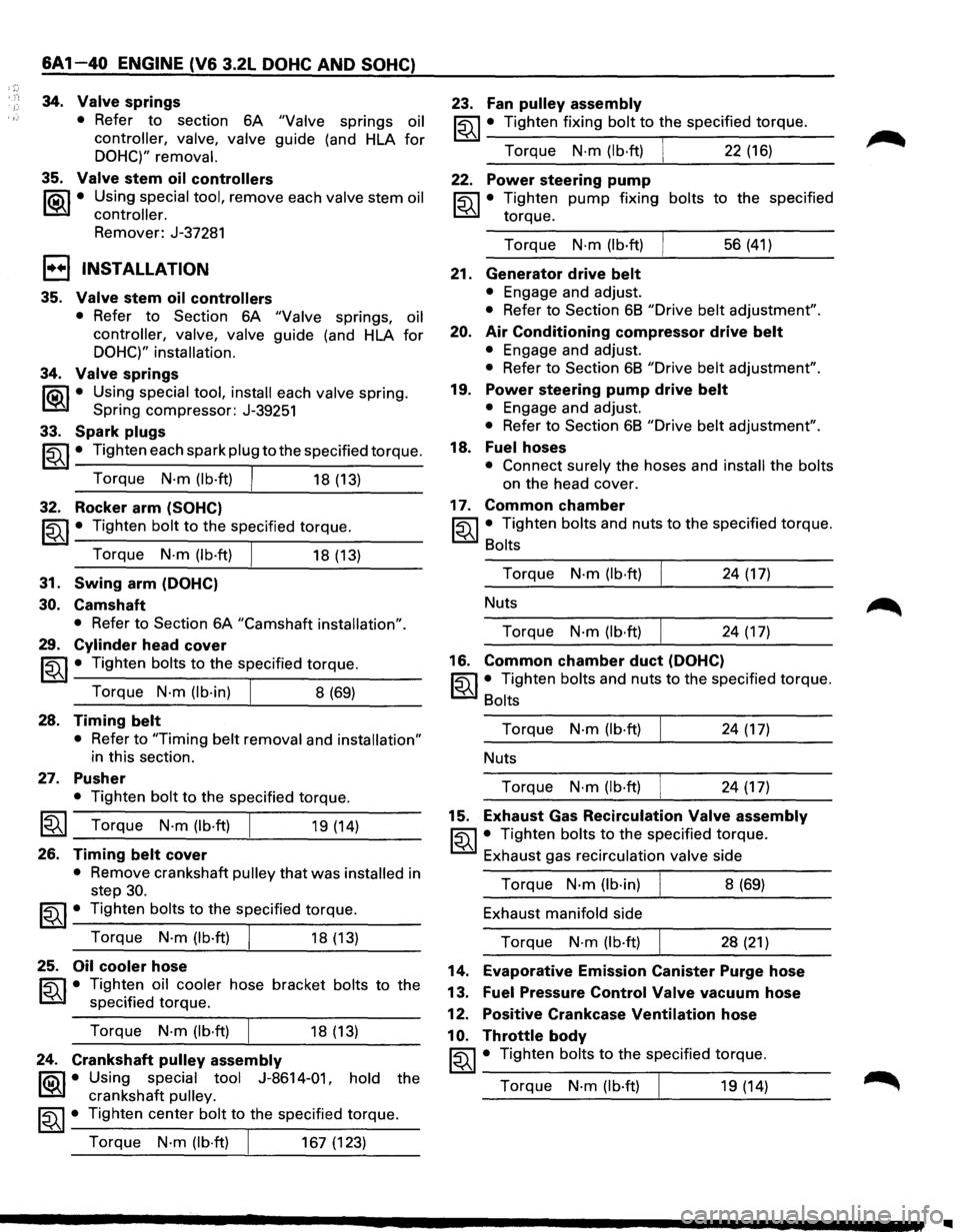
34. Valve springs
35.
• Refer to section 6A "Valve springs oil
controller, valve, valve guide (and HLA for
DOHC)" removal.
Valve stem oil controllers
~·
Using special tool, remove each valve stem oil
controller.
Remover: J-37281
1••1 INSTALLATION
35. Valve stem oil controllers
• Refer to Section 6A "Valve springs, oil
controller, valve, valve guide (and HLA for
DOHC)" installation.
34. Valve springs
li5\l • Using special tool, install each valve spring.
~ Spring compressor: J-39251
33. Spark plugs
~~~· Tighten each spark plug to the specified torque.
Torque
N·m (lb·ft) I 18 (13)
32. Rocker arm (SOHC)
~~~ • Tighten bolt to the specified torque.
Torque
N·m (lb·ft) I 18 (13)
31. Swing arm (DOHC)
30. Camshaft
• Refer to Section 6A "Camshaft installation".
29. Cylinder head cover
~~~ • Tighten bolts to the specified torque.
Torque
N-m (lb·in) I 8 (69)
28. Timing belt
• Refer to "Timing belt removal and installation"
in this section.
27. Pusher
• Tighten bolt to the specified torque.
~~~ Torque N·m (lb·ft) 19 (14)
26. Timing belt cover
• Remove crankshaft pulley that was installed in
step
30.
~~~· Tighten bolts to the specified torque.
Torque
N·m (lb-ft) I 18 (13)
25. Oil cooler hose
~ • Tighten oil cooler hose bracket bolts to the
~ specified torque.
Torque
N-m (lb·ft) I 18 (13)
24. Crankshaft pulley assembly
f'Qil • Using special tool J-8614-01, hold the
~ crankshaft pulley.
~~~· Tighten center bolt to the specified torque.
Torque
N·m (lb·ft) I 167 (123)
23. Fan pulley assembly
~~~ • Tighten fixing bolt to the specified torque.
Torque
N·m (lb·ft) I 22 (16)
22. Power steering pump
~ • Tighten pump fixing bolts to the specified
~ torque.
Torque
N·m (lb·ft) 56 (41)
21. Generator drive belt
• Engage and adjust.
• Refer to Section 6B "Drive belt adjustment".
20. Air Conditioning compressor drive belt
• Engage and adjust.
• Refer to Section 6B "Drive belt adjustment".
19. Power steering pump drive belt
• Engage and adjust.
• Refer to Section 6B "Drive belt adjustment".
18. Fuel hoses
• Connect surely the hoses and install the bolts
on the head cover.
17. Common chamber
~~~· Tighten bolts and nuts to the specified torque.
Bolts
Torque
N-m (lb·ft) 24 (17)
Nuts
Torque
N·m (lb·ft) 24 (17)
16. Common chamber duct (DOHC)
~~~ • Tighten bolts and nuts to the specified torque.
Bolts
Torque
N·m (lb·ft) 24 (17)
Nuts
Torque
N·m (lb·ft) 24 (17)
15. Exhaust Gas Recirculation Valve assembly
~~~· Tighten bolts to the specified torque.
Exhaust gas recirculation valve side
Torque
N·m (lb-in) 8 (69)
Exhaust manifold side
Torque
N-m (lb·ft) 28 (21)
14. Evaporative Emission Canister Purge hose
13. Fuel Pressure Control Valve vacuum hose
12. Positive Crankcase Ventilation hose
10. Throttle body
~~~ • Tighten bolts to the specified torque.
Torque
N-m (lb·ft) I 19 (14)
..
Page 689 of 1928
IGNITION SYSTEM 6D4 - 1
SECTION 604
IGNITION SYSTEM
CONTENTS
General Description ...................... .
Diagnosis
................................... .
On-Vehicle Service ....................... .
Spark Plug Wire ....................... .
Spark Plug .............................. . 6D4-1
6D4-2 6D4-3
6D4-3
6D4-3
Electronic Ignition (EI) Assembly ...
Crankshaft Position Sensor
(CKP sensor) ........................ .
Torque Specifications
................ .
Main Data and Specifications
......... . 6D4-5
6D4-5
6D4-6
6D4-7
GENERAL DESCRIPTION
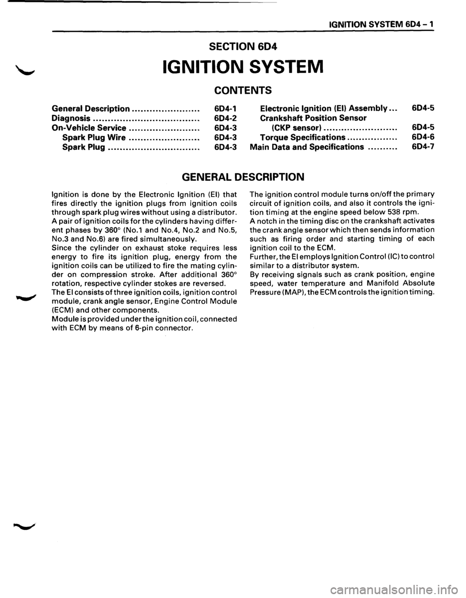
Ignition is done by the Electronic Ignition (EI) that
fires directly the ignition plugs from ignition coils
through spark plug wires without using a distributor.
A pair of ignition coils for the cylinders having differ
ent phases by 360° (No.1 and No.4, No.2 and No.5,
No.3 and No.6) are
fired simultaneously.
Since the cylinder on exhaust stoke requires less
energy to fire its ignition plug, energy from the
ignition coils can be utilized to fire the mating cylin
der on compression stroke. After additional 360°
rotation, respective cylinder stokes are reversed.
TheEl consists of three ignition coils, ignition control
module, crank angle sensor, Engine Control Module
(ECM) and other components.
Module is provided under the ignition coil, connected
with ECM by means of 6-pin connector. The
ignition control module turns on/off the primary
circuit of ignition coils, and also it controls the igni
tion timing at the engine
speed below 538 rpm.
A notch in
the timing disc on the crankshaft activates
the crank angle sensor which then sends information
such as firing order and starting timing of each
ignition coil to the ECM.
Further, the El employs Ignition Control (I C) to control
similar to a distributor system.
By receiving
signals such as crank position, engine
speed, water temperature and Manifold Absolute
Pressure (MAP), the ECM controls the ignition timing.
Page 691 of 1928
![ISUZU TROOPER 1995 User Guide IGNITION SYSTEM 604 - 3
ON-VEHICLE SERVICE
SPARK PLUG WIRES
EJ REMOVAL
Preparation
• Disconnect battery ground cable.
1. Spark plug wires (Fig. 604-2)
Fig. 6D4-2
(1!] INSPECTION AND REPAIR](/img/61/57183/w960_57183-690.png "ISUZU TROOPER 1995 User Guide IGNITION SYSTEM 604 - 3
ON-VEHICLE SERVICE
SPARK PLUG WIRES
EJ REMOVAL
Preparation
• Disconnect battery ground cable.
1. Spark plug wires (Fig. 604-2)
Fig. 6D4-2
(1!] INSPECTION AND REPAIR")
IGNITION SYSTEM 604 - 3
ON-VEHICLE SERVICE
SPARK PLUG WIRES
EJ REMOVAL
Preparation
• Disconnect battery ground cable.
1. Spark plug wires (Fig. 604-2)
Fig. 6D4-2
(1!] INSPECTION AND REPAIR
Check the high tension cable for insulation. Check
terminals for corrosion or damage, and replace as
necessary.
Measuring resistance of spark plug wires (kQ)
Spare plug wires SOHC DOHC
No.1 cable 6.4-14.9 6.2-14.2
No.2 cable 5.7-13.1 7.2-16.7
No.3 cable 6.2-14.4 6.5-14.9
No.4 cable 5.8-13.3 6.8-15.8
No.5 cable 6.4-14.9 6.9-16.0
No.6 cable 6.9-16.0 6.3-14.5
Measure resistance
of spark plug wires, and replace
the cable if its value exceeds the standard. (Fig. 6D4-
3)
Fig. 6D4-3
B INSTALLATION
1. Spark plug wires
• Connect ignition coils and spark plugs with
spark plug wires respectively. Match each
number (cylinder No.) marked on the ignition
coil with that on spark plug wire, and connect
each spark
plug for the cylinder. (Fig. 6D4-4)
LH bank
y Front
#4-
#1--
1®®®1
RH Bank
Connecting Position of Spark plug wire
Fig. 6D4-4
• Connect battery ground cable.
"f CAUTION
Do not cross, twist or pull the spark plug wires.
SPARK PLUG
EJ REMOVAL
1. Spare plug wires
2. Spark plugs (Fig. 604-5)
Page 692 of 1928
604-4 IGNITION SYSTEM
Fig. 604A-5
~ INSPECTION AND REPAIR
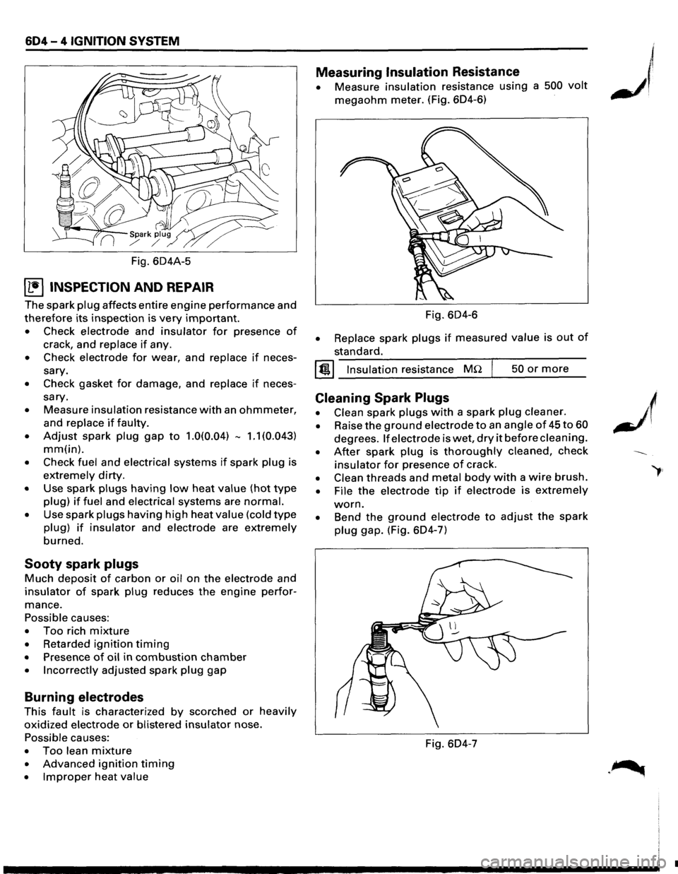
The spark plug affects entire engine performance and
therefore its inspection is very important.
• Check electrode and insulator for presence of
crack, and replace if any.
• Check electrode for wear, and replace if neces
sary.
• Check gasket for damage, and replace if neces
sary.
• Measure insulation resistance with an ohmmeter,
and replace if faulty.
• Adjust spark plug gap to 1.0(0.04) -1.1 (0.043)
mm(in).
• Check fuel and electrical systems if spark plug is
extremely dirty.
• Use spark plugs having low heat value (hot type
plug) if fuel and electrical systems are normal.
• Use spark plugs having high heat value (cold type
plug) if insulator and electrode are extremely
burned.
Sooty spark plugs
Much deposit of carbon or oil on the electrode and
insulator of spark plug reduces the engine perfor
mance.
Possible causes:
• Too rich mixture
• Retarded ignition timing
• Presence of oil in combustion chamber
• Incorrectly adjusted spark plug gap
Burning electrodes
This fault is characterized by scorched or heavily
oxidized electrode or blistered insulator nose.
Possible causes:
• Too lean mixture
• Advanced ignition timing
• Improper heat value
Measuring Insulation Resistance
• Measure insulation resistance using a 500 volt
megaohm meter. (Fig. 604-6)
Fig.
604-6
• Replace spark plugs if measured value is out of
standard.
I @!.j Insulation resistance MQ 50 or more
Cleaning Spark Plugs
• Clean spark plugs with a spark plug cleaner.
• Raise the ground electrode to an angle of 45 to 60
degrees. If electrode is wet, dry it before cleaning.
• After spark plug is thoroughly cleaned, check
insulator for presence of crack.
• Clean threads and metal body with a wire brush.
• File the electrode tip if electrode is extremely
worn.
• Bend the ground electrode to adjust the spark
plug gap. (Fig. 604-7)
Fig. 604-7
•
Page 693 of 1928
[!!) INSTALLATION
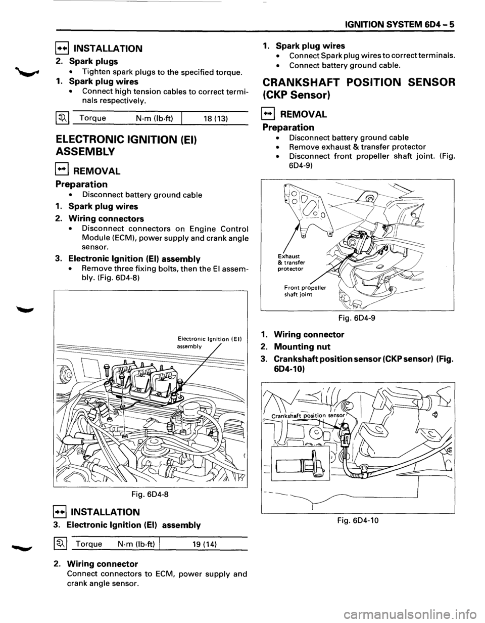
2. Spark plugs
• Tighten spark plugs to the specified torque.
1. Spark plug wires
• Connect high tension cables to correct termi
nals respectively.
~~~ Torque N·m (lb·ft) I
ELECTRONIC IGNITION (EI)
ASSEMBLY
EJ REMOVAL
Preparation
• Disconnect battery ground cable
1. Spark plug wires
2. Wiring connectors
18 (13)
• Disconnect connectors on Engine Control
Module (ECM), power supply and crank angle
sensor.
3. Electronic Ignition (EI) assembly
• Remove three fixing bolts, then the El assem
bly. (Fig. 6D4-8)
Fig. 6D4-8
E]INSTALLATION
Electronic Ignition (Ell assembly
3. Electronic Ignition (EI) assembly
~~~ Torque N·m (lb·ftl I 19 (14)
2. Wiring connector
Connect connectors to ECM, power supply and
crank
angle sensor.
IGNITION SYSTEM 604-5
1. Spark plug wires
• Connect Spark plug wires to correct terminals.
• Connect battery ground cable.
CRANKSHAFT POSITION SENSOR
(CKP Sensor)
E) REMOVAL
Preparation
• Disconnect battery ground cable
•
Remove exhaust & transfer protector
• Disconnect front propeller shaft joint. (Fig.
6D4-9)
Fig. 6D4-9
1. Wiring connector
2. Mounting nut
3. Crankshaft position sensor (CKP sensor) (Fig.
604-10)
Fig. 6D4-10
Page 720 of 1928
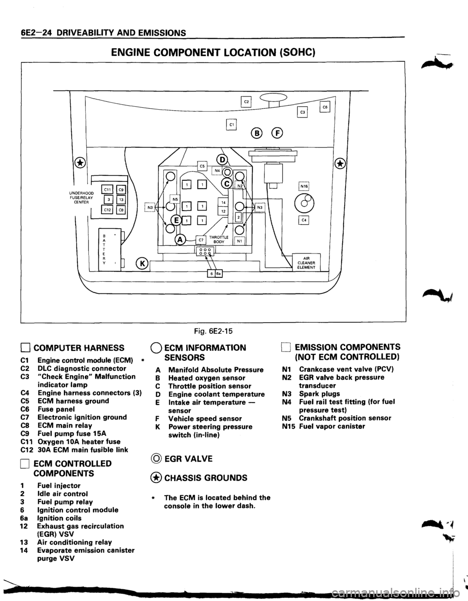
6E2-24 DRIVEABILITY AND EMISSIONS
ENGINE COMPONENT LOCATION (SOHC)
UNDERHOOD
FUSE/RELAY
CENTER
8 A
T
T
E
R y
0 COMPUTER HARNESS
C1 Engine control module (ECM) *
C2 DLC diagnostic connector
C3 "Check Engine" Malfunction
indicator lamp
C4 Engine harness connectors (3)
C5 ECM harness ground
C6 Fuse panel
C7 Electronic ignition ground
CS ECM main relay
C9 Fuel pump fuse 15A
C11 Oxygen 1 OA heater fuse
C12 30A ECM main fusible link
0 ECM CONTROLLED
COMPONENTS
1 Fuel injector
2 Idle air control
3 Fuel pump relay
6 Ignition control module
6a Ignition coils
12 Exhaust gas recirculation
(EGR) VSV
13 Air conditioning relay
14 Evaporate emission canister
purge VSV
Fig. 6E2-15
Q ECM INFORMATION
SENSORS
®
A Manifold Absolute Pressure
B Heated oxygen sensor
C Throttle position sensor
D Engine
coolant temperature
E Intake air temperature -
sensor
F Vehicle speed sensor
K Power steering pressure
switch (in-line)
@ EGRVALVE
@CHASSIS GROUNDS
* The ECM is located behind the
console in the lower dash.
®
[::::J EMISSION COMPONENTS
(NOT
ECM CONTROLLED)
N1 Crankcase vent valve (PCV)
N2 EGR valve back pressure
transducer
N3 Spark plugs
N4 Fuel rail test fitting (for fuel
pressure test)
N5 Crankshaft position sensor
N15 Fuel vapor canister
Page 721 of 1928
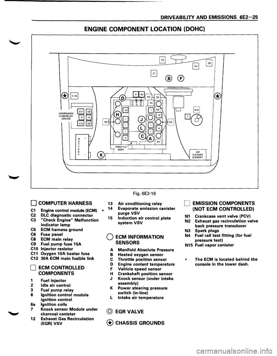
DRIVEABILITY AND EMISSIONS 6E2-25
ENGINE COMPONENT LOCATION (DOHC)
®B
UNDERHOOD FUSE/RELAY CENTER
B A T
T
E
A y
0 COMPUTER HARNESS
C1 Engine control module (ECM)
C2 DLC diagnostic connector
C3 "Check Engine" Malfunction
indicator lamp
C5 ECM harness ground
C6 Fuse panel
C8 ECM main relay
C9 Fuel pump fuse 15A
C10 Injector resistor
C11 Oxygen 1 OA heater fuse
C12
30A ECM main fusible link
0 ECM CONTROLLED
COMPONENTS
1 Fuel injector
2 Idle air control
3 Fuel pump relay
6 Ignition control module
ignition control
6a Ignition coils
7 Knock sensor Module under
charcoal canister
12
Exhaust Gas Recirculation
(EGR) VSV
*
®®
Fig. 6E2-16
13 Air conditioning relay
14 Evaporate emission canister
purge VSV
15 Induction air control plate
system VSV
Q ECM INFORMATION
SENSORS
A Manifold Absolute Pressure
B Heated oxygen sensor
c Throttle position sensor
D Engine
coolant temperature
F Vehicle speed sensor
H Crankshaft
position sensor
J Knock sensor
(under intake
assembly)
K Power steering pressure
switch (in-line)
L Intake air temperature
@ EGRVALVE
@ CHASSIS GROUNDS
f----1 EMISSION COMPONENTS !.-----' (NOT ECM CONTROLLED)
N1 Crankcase vent valve (PCV)
N2 Exhaust gas
recirculation valve
back pressure transducer
N3 Spark plugs
N4 Fuel rail test fitting (for fuel
pressure test)
N15 Fuel vapor canister
* The ECM is located behind the
console in the lower dash.
Page 738 of 1928
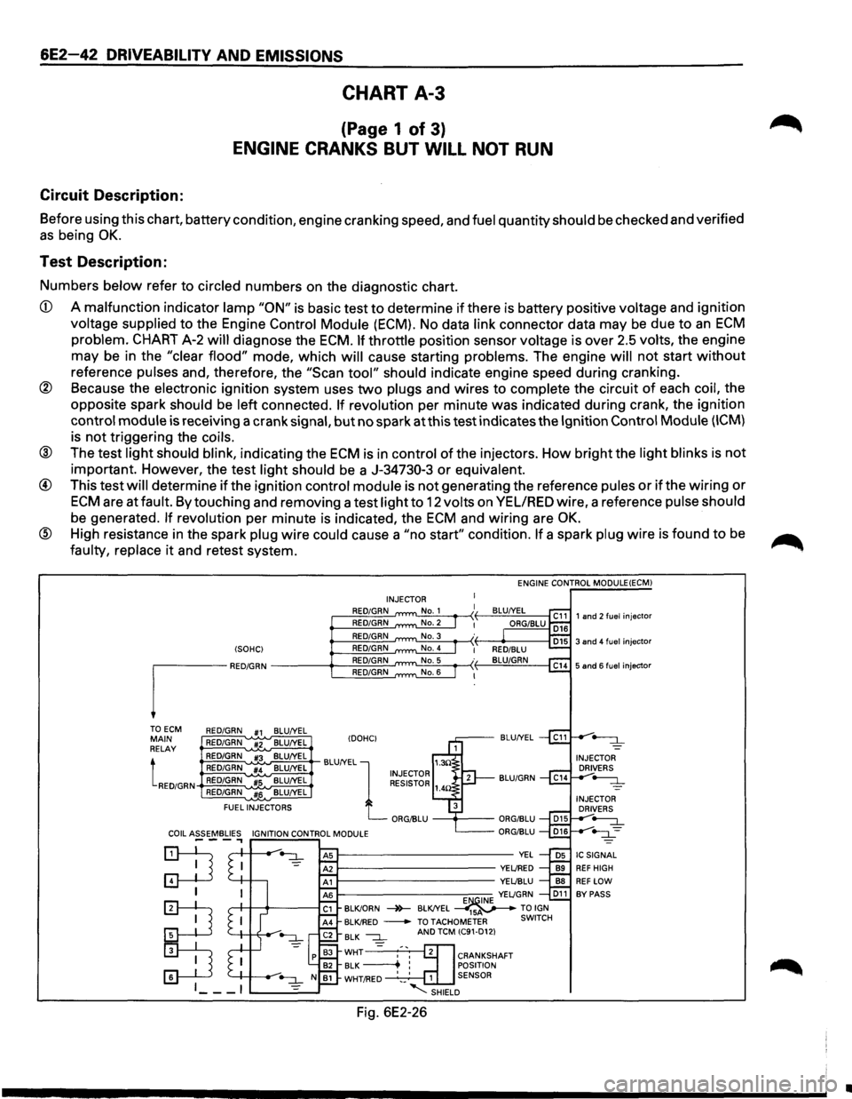
6E2-42 DRIVEABILITV AND EMISSIONS
CHART A-3
(Page 1 of 3)
ENGINE CRANKS BUT WILL NOT RUN
Circuit Description:
Before using this chart, battery condition, engine cranking speed, and fuel quantity should be checked and verified
as being OK.
Test Description:
Numbers below refer to circled numbers on the diagnostic chart.
CD A malfunction indicator lamp "ON" is basic test to determine if there is battery positive voltage and ignition
voltage supplied to the Engine Control Module (ECM). No data link connector data may be due to an ECM
problem. CHART A-2 will diagnose the ECM. If throttle position sensor voltage is over 2.5 volts, the engine
may be in the
"clear flood" mode, which will cause starting problems. The engine will not start without
reference pulses and, therefore, the "Scan tool" should indicate engine speed during cranking.
@ Because the electronic ignition system uses two plugs and wires to complete the circuit of each coil, the
opposite spark
should be left connected. If revolution per minute was indicated during crank, the ignition
control module is receiving a crank signal, but no spark at this test indicates the Ignition Control Module (ICM)
is not triggering the coils.
® The test light should blink, indicating the ECM is in control of the injectors. How bright the light blinks is not
important. However, the test light should be a J-34730-3 or equivalent.
@ This test will determine if the ignition control module is not generating the reference pules or if the wiring or
ECM are at fault. By touching and removing a test light to 12 volts on VEL/RED wire, a reference pulse should
be generated. If revolution per minute is indicated, the ECM and wiring are OK.
® High resistance in the spark plug wire could cause a "no start" condition. If a spark plug wire is found to be
faulty, replace it and retest system.
(SOHC)
I"M"
TOECM RED/GRN #1 BLU/YEL MAIN RED/GRN #2 BLU/YEL
RELAY
tRED/GRN
RED/GRN #3 BLU/YEL
RED/GRN #4 BLU/YEL
RED/GRN
#5 BLU/YEL
RED/GRN
#6 BLU/YEL
FUEL
INJECTORS ENGINE
CONTROL MODULE(ECM)
INJECTOR
RED/GRN
RED/GRN
RED/GRN
RED/GRN
RED/GRN
RED/GRN
IDOHCI BLU/YEL
BLU/YEL
l 1.3!l INJECTOR RESISTOR 1_
ORG/BLU
--+----
E~INE YEL/GRN D11 BLK/ORN -4>-BLK/YEL ----41sv---TO IGN BLK/RED -TOTACHOMETER SWITCH
BLK --:::L =
AND TCM (C91-D12)
CRANKSHAFT
POSITION
1 SENSOR
-........:::SHIELD
Fig. 6E2-26
•
Page 742 of 1928
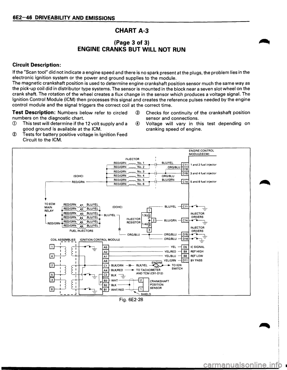
6E2-46 DRIVEABILITV AND EMISSIONS
CHART A-3
(Page 3 of 3)
ENGINE CRANKS BUT WILL NOT RUN
Circuit Description:
If the "Scan tool" did not indicate a engine speed and there is no spark present at the plugs, the problem lies in the
electronic ignition system
or the power and ground supplies to the module.
The magnetic crankshaft position is used to determine engine crankshaft position sensor much the same way as
the pick-up coil did in distributor type systems. The sensor is mounted in the block near a seven slot wheel on the
crank shaft. The rotation
of the wheel creates a flux change in the sensor which produces a voltage signal. The
Ignition Control Module (ICM) then processes this signal and creates the reference pulses needed by the engine
control module and the signal triggers the correct coil at the correct time.
Test Description: Numbers below refer to circled ® Checks for continuity of the crankshaft position
numbers on the diagnostic chart. sensor and connections.
available at the ICM. cranking speed of engine.
® Tests for battery positive voltage in Ignition Feed
Circuit to the
ICM.
TO ECM RED/GRN #1 BLU/YEL MAIN RELAY
tRED/GRN
RED/GRN #2 BLU/YEL
RED/GRN #3 BLU/YEL
RED/GRN '"#4 BLU/YEL RED/GRN #5 BLU/YEL RED/GRN #6 BLU/YEL
FUEL
INJECTORS INJECTOR
RED/GRN RED/GRN RED/GRN
E"'QINE YELJGRN D11 BLK!ORN ----)>--BLK!YEL _____..,-~ TO IGN BLK!RED
-TO TACHOMETER SWITCH BLK --:::J_ AND TCM (C91-D12)
WHT2cl]= :-·-, 2 CRANKSHAFT BLK ~ : POSITION WHT/RED · __ ,' 1 SENSOR
'-;SHIELD
Fig. 6E2-28
ENGINE CONTROL
MODULEIECM)
1 and 2 fuel injector
•
Page 747 of 1928
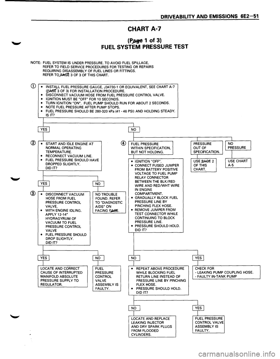
DRIVEABILITV AND EMISSIONS 6E2-51
CHART A-7
(PJtge 1 of 3}
FUEL SYSTEM PRESSURE TEST
NOTE: FUEL SYSTEM IS UNDER PRESSURE. TO AVOID FUEL SPILLAGE, REFER TO FIELD SERVICE PROCEDURES FOR TESTING OR REPAIRS
REQUIRING DISASSEMBLY OF FUEL LINES OR FITTINGS. REFER TO~ 3 OF 3 OF THIS CHART.
CD • INSTALL FUEL PRESSURE GAUGE, J34730-1 OR EQUIVALENT, SEE CHART A-7 ~3 OF 3) FOR INSTALLATION PROCEDURE.
• DISCONNECT VACUUM HOSE FROM FUEL PRESSURE CONTROL VALVE.
• IGNITION MUST BE "OFF" FOR 10 SECONDS.
• TURN IGNITION "ON". FUEL PUMP SHOULD RUN FOR ABOUT 2 SECONDS.
• NOTE FUEL PRESSURE AFTER PUMP STOPS.
• FUEL PRESSURE SHOULD BE 280-320 kPa (41-46 PSI) AND HOLDING STEADY. IS IT?
I
• START AND IDLE ENGINE AT NORMAL OPERATING TEMPERATURE. • RECONNECT VACUUM LINE.
• FUEL PRESSURE SHOULD HAVE
DROPPED SLIGHTLY.
DID IT?
I
@ FUEL PRESSURE
WITHIN SPECIFICATION,
BUT NOT HOLDING.
• IGNITION "OFF".
.---'---$YES
-$r---'--NO -
@ • DISCONNECT VACUUM NO TROUBLE •
CONNECT FUSED
JUMPER FROM BATTERY POSITIVE
VOLTAGE TO FUEL PUMP
RELAY CONNECTOR BETWEEN THE BLK/RED WIRE AND RED/WHT WIRE IN ENGINE
COMPARTMENT.
HOSE FROM
FUEL FOUND. REFER PRESSURE CONTROL TO "DIAGNOSTIC
VALVE. AIDS" ON
• WITH ENGINE IDLING. FACING P.A@f. APPLY 12-14"
HYDRAGYRUM OF VACUUM TO FUEL PRESSURE CONTROL
VALVE
•
FUEL PRESSURE SHOULD DROP SLIGHTLY.
DID IT?
I
• GRADUALLY BLOCK FUEL PRESSURE LINE BY PINCHING FLEX HOSE.
• REMOVE JUMPER FROM
TEST CONNECTOR WHILE
CONTINUING TO BLOCK
PRESSURE LINE.
• PRESSURE SHOULD HOLD.
DID
IT?
I PRESSURE
OUT OF SPECIFICATION.
I USE,.eAef 2 OF THIS CHART.
I
INO I PRESSURE
I
I USE CHART I A-5
~~NLO------------------~ $~YELS---------------------, LOCATE AND CORRECT
CAUSE OF INTERRUPTED
MANIFOLD ABSOLUTE
PRESSURE SUPPLY TO
REGULATOR. FUEL PRESSURE
CONTROL VALVE ASSEMBLY
IS FAULTY.
• REPEAT ABOVE PROCEDURE CHECK FOR WHILE BLOCKING FUEL -LEAKING PUMP COUPLING HOSE. RETURN LINE INSTEAD OF -FAUL TV IN-TANK PUMP PRESSURE LINE BY PINCHING FLEX HOSE.
• PRESSURE SHOULD HOLD.
DID
IT?
LOCATE AND REPLACE LEAKING INJECTOR AND DRY SPARK PLUGS
FROM FLOODED
CYLINDERS.
FUEL PRESSURE
CONTROL VALVE
ASSEMBLY
IS FAULTY.