steering wheel adjustment ISUZU TROOPER 1995 User Guide
[x] Cancel search | Manufacturer: ISUZU, Model Year: 1995, Model line: TROOPER, Model: ISUZU TROOPER 1995Pages: 1928
Page 143 of 1928
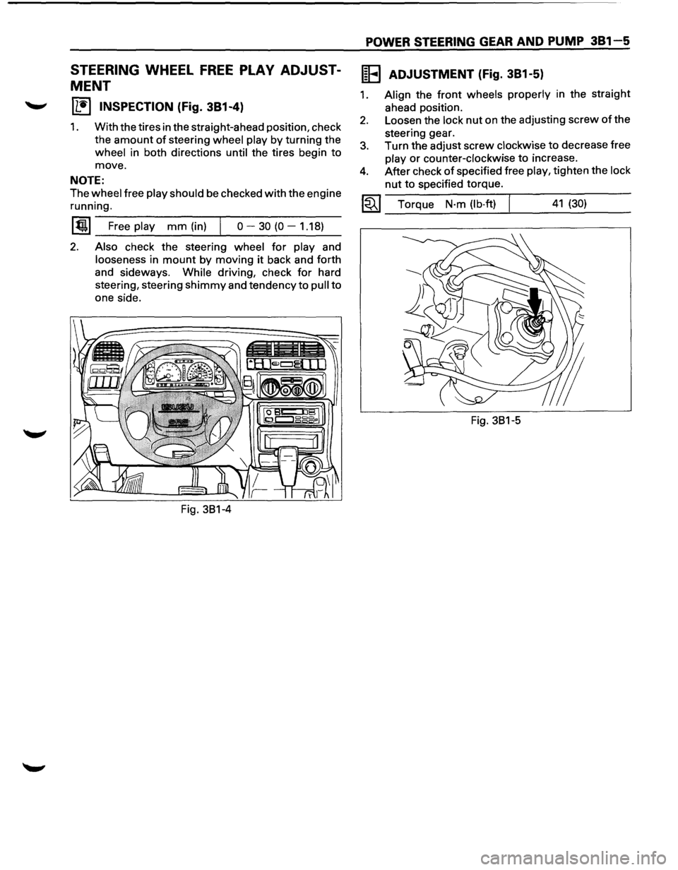
STEERING WHEEL FREE PLAY ADJUST
MENT
IL•I INSPECTION (Fig. 381-4)
1. With the tires in the straight-ahead position, check
the
amount of steering wheel play by turning the
wheel in both directions until the tires begin to
move.
NOTE:
The wheel free play should be checked with the engine
running.
~~~~F-r-ee--pl-ay---m-m--(in_)_,j--o----3-0-(0----1-.1-8~)-
2. Also check the steering wheel for play and
looseness in mount by moving it back and forth
and sideways.
While driving, check for hard
steering, steering
shimmy and tendency to pull to
one side.
POWER STEERING GEAR AND PUMP 381-5
IEEI ADJUSTMENT (Fig. 381-5)
1. Align the front wheels properly in the straight
ahead position.
2. Loosen the lock nut on the adjusting screw of the
steering gear.
3. Turn the adjust screw clockwise to decrease free
play or counter-clockwise to incre~se.
4. After check of specified free play, t1ghten the lock
nut to specified torque.
~~~ Torque N·m (lb·ft) I 41 (30)
Fig. 381-5
Page 157 of 1928
STEERING LINKAGE 383-1
SECTION 383
STEERING LINKAGE
w CAUTION:
• When fasteners are removed, always reinstall them at the same location from which they were removed. If a
fastener needs
to be replaced, use the correct part number fastener for that application. If the correct part
number fastener is not available, a fastener of equal size and strength (or stronger) may be used. Fasteners
that are not reused, and those requiring thread locking compound, will be called out. The correct torque
value must be used when installing fasteners that require it. If the above conditions are not followed, parts or
system damage could result.
CONTENTS
General Description . . . . . . . . . . . . . . . . . . . . 383-1
On-Vehicle Service .................... 383-2
Center Track Rod Assembly . . . . . . . . . . . 383-2
Outer Track Rod Assembly . . . . . . . . . . . . 383-4
Relay Lever . . . . . . . . . . . . . . . . . . . . . . . . . 383-6 Main
Data
and Specifications ............ 383-8
Torque Specifications
................ 383-8
Special Tools .......................... 383-8
GENERAL DESCRIPTION
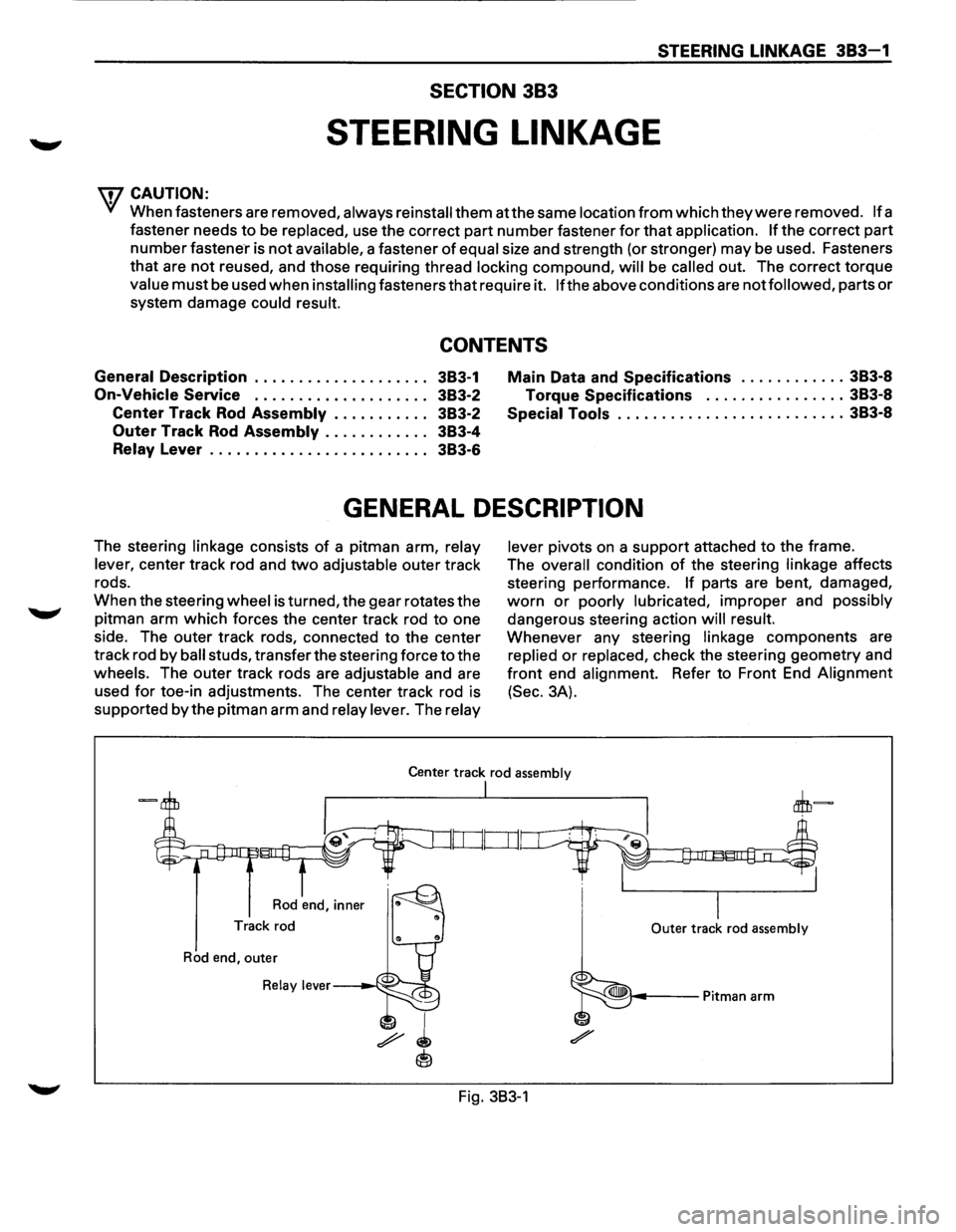
The steering linkage consists of a pitman arm, relay
lever,
center track rod and two adjustable outer track
rods.
When the steering
wheel is turned, the gear rotates the
pitman arm
which forces the center track rod to one
side. The outer track rods, connected to the center
track rod
by ball studs, transfer the steering force to the
wheels. The outer track rods are adjustable and are
used
for toe-in adjustments. The center track rod is
supported
by the pitman arm and relay lever. The relay lever
pivots
on a support attached to the frame.
The
overall condition of the steering linkage affects
steering performance.
If parts are bent, damaged,
worn or poorly lubricated, improper and possibly
dangerous steering action will result.
Whenever any steering linkage components are
replied or replaced, check the steering geometry and
front end alignment. Refer to Front End Alignment
(Sec. 3A).
Center track rod assembly
Rod end, inner
Track rod
Rod end, outer
Relay lever---~·--:;:::jo
I
I Outer track rod assembly
Fig. 383-1
Page 280 of 1928
4C-2 FRONT DRIVING AXLE
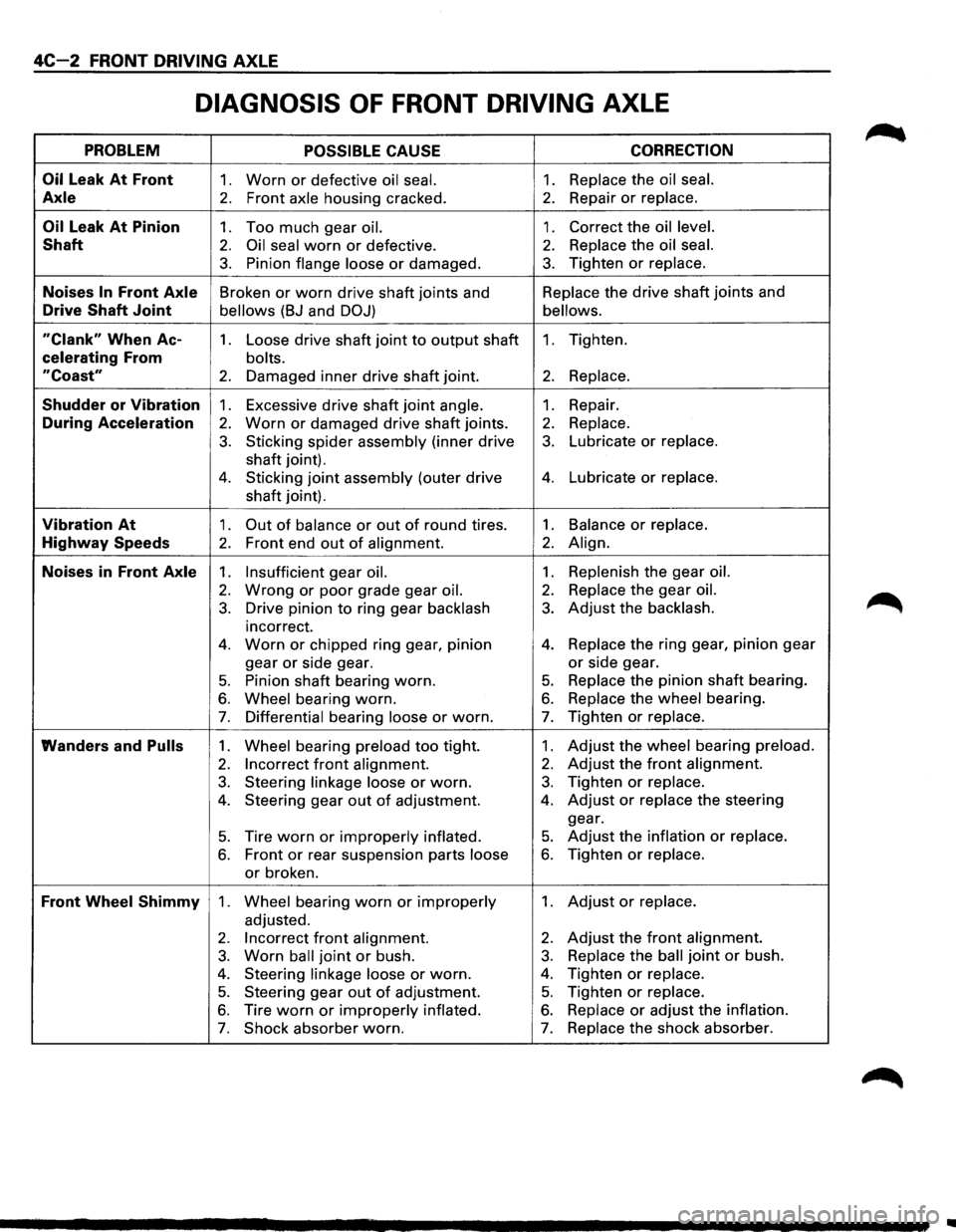
DIAGNOSIS OF FRONT DRIVING AXLE
PROBLEM POSSIBLE CAUSE CORRECTION
Oil
Leak At Front 1. Worn or defective oil seal. 1. Replace the oil seal.
Axle 2. Front axle housing cracked. 2. Repair or replace.
Oil Leak At Pinion 1. Too much gear oil. 1. Correct the oil level.
Shaft 2. Oil seal worn or defective. 2. Replace the oil seal.
3. Pinion flange loose or damaged. 3. Tighten or replace.
Noises In Front Axle Broken or worn drive shaft joints and Replace
the drive shaft joints and
Drive Shaft Joint bellows (BJ and DOJ) bellows.
"Clank" When Ac-1. Loose drive shaft joint to output shaft 1. Tighten.
celerating From bolts.
"Coast" 2. Damaged inner drive shaft joint. 2. Replace.
Shudder or Vibration 1. Excessive drive shaft joint angle. 1. Repair.
During Acceleration 2. Worn or damaged drive shaft joints. 2. Replace.
3. Sticking spider assembly (inner drive 3. Lubricate or replace.
shaft joint).
4. Sticking joint assembly (outer drive 4. Lubricate or replace.
shaft joint).
Vibration At 1. Out of balance or out of round tires. 1. Balance or replace.
Highway Speeds 2. Front end out of alignment. 2. Align.
Noises in Front Axle 1. Insufficient gear oil. 1. Replenish the gear oil.
2. Wrong or poor grade gear oil. 2. Replace the gear oil.
3. Drive pinion to ring gear backlash 3. Adjust the backlash.
incorrect.
4. Worn or chipped ring gear, pinion 4. Replace the ring gear, pinion gear
gear
or side gear. or side gear.
5. Pinion shaft bearing worn. 5. Replace the pinion shaft bearing.
6. Wheel bearing worn. 6. Replace the wheel bearing.
7. Differential bearing loose or worn. 7. Tighten or replace.
Wanders and Pulls 1. Wheel bearing preload too tight. 1. Adjust the wheel bearing preload.
2. Incorrect front alignment. 2. Adjust the front alignment.
3. Steering linkage loose or worn. 3. Tighten or replace.
4. Steering gear out of adjustment. 4. Adjust or replace the steering
gear.
5. Tire worn or improperly inflated. 5. Adjust the inflation or replace.
6. Front or rear suspension parts loose 6. Tighten or replace.
or broken.
Front Wheel Shimmy 1. Wheel bearing worn or improperly 1. Adjust or replace.
adjusted.
2. Incorrect front alignment. 2. Adjust the front alignment.
3. Worn ball joint or bush. 3. Replace the ball joint or bush.
4. Steering linkage loose or worn. 4. Tighten or replace.
5. Steering gear out of adjustment. 5. Tighten or replace.
6. Tire worn or improperly inflated. 6. Replace or adjust the inflation.
7. Shock absorber worn. 7. Replace the shock absorber.
..
Page 803 of 1928
New or service sensors will already have the
compound
applied to the threads. If a sensor is
removed
from an engine and iffor any reason it
is to be reinstalled, the threads must have anti
seize compound
applied before reinstallation.
•
Apply anti-seize compound or equivalent to
threads of oxygen sensor if necessary.
• Tighten the oxygen sensor to the specified
torque.
1~1 Torque N·m (lb·ft) 55 (40)
1. H02S wiring connector
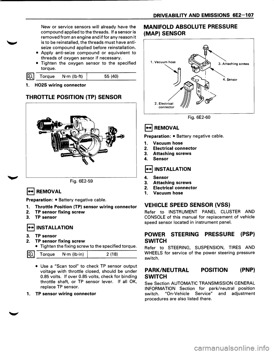
THROTTLE POSITION (TP) SENSOR
Fig. 6E2-59
E) REMOVAL
Preparation: • Battery negative cable.
1. Throttle Position (TP) sensor wiring connector
2. TP sensor fixing screw
3. TP sensor
I••IINSTALLATION
3. TP sensor
2. TP sensor fixing screw
• Tighten the fixing screw to the specified torque.
~~~ Torque N·m (lb·in) I 2 (18)
• Use a "Scan tool" to check TP sensor output
voltage with throttle closed, should be under
0.85 volts. If over 0.85 volts, check for binding
throttle shaft, or TP sensor lever. If all OK,
replace TP sensor.
1.
TP sensor wiring connector
DRIVEABILITY AND EMISSIONS 6E2-1 07
MANIFOLD ABSOLUTE PRESSURE
(MAP) SENSOR
1. Vacuum hose
) 0~
2 .• ,.~,,~,~
conne~ JJJ
4. Sensor
Fig. 6E2-60
E) REMOVAL
Preparation: • Battery negative cable.
1. Vacuum hose
2. Electrical connector
3. Attaching screws
4. Sensor
I••IINSTALLATION
4. Sensor
3. Attaching screws
2. Electrical connector
1. Vacuum hose
VEHICLE SPEED SENSOR (VSS)
Refer to INSTRUMENT PANEL CLUSTER AND
CONSOLE of this manual for replacement of vehicle
speed sensor located in instrument panel.
POWER STEERING PRESSURE (PSP)
SWITCH
Refer to STEERING, SUSPENSION, TIRES AND
WHEELS for service of the power steering pressure
switch.
PARK/NEUTRAL
SWITCH POSITION
(PNP}
See
Section AUTOMATIC TRANSMISSION GENERAL
INFORMATION Section for park/neutral position
switch.
"On-Vehicle Service" and adjustment
procedures are
also listed there.
Page 823 of 1928
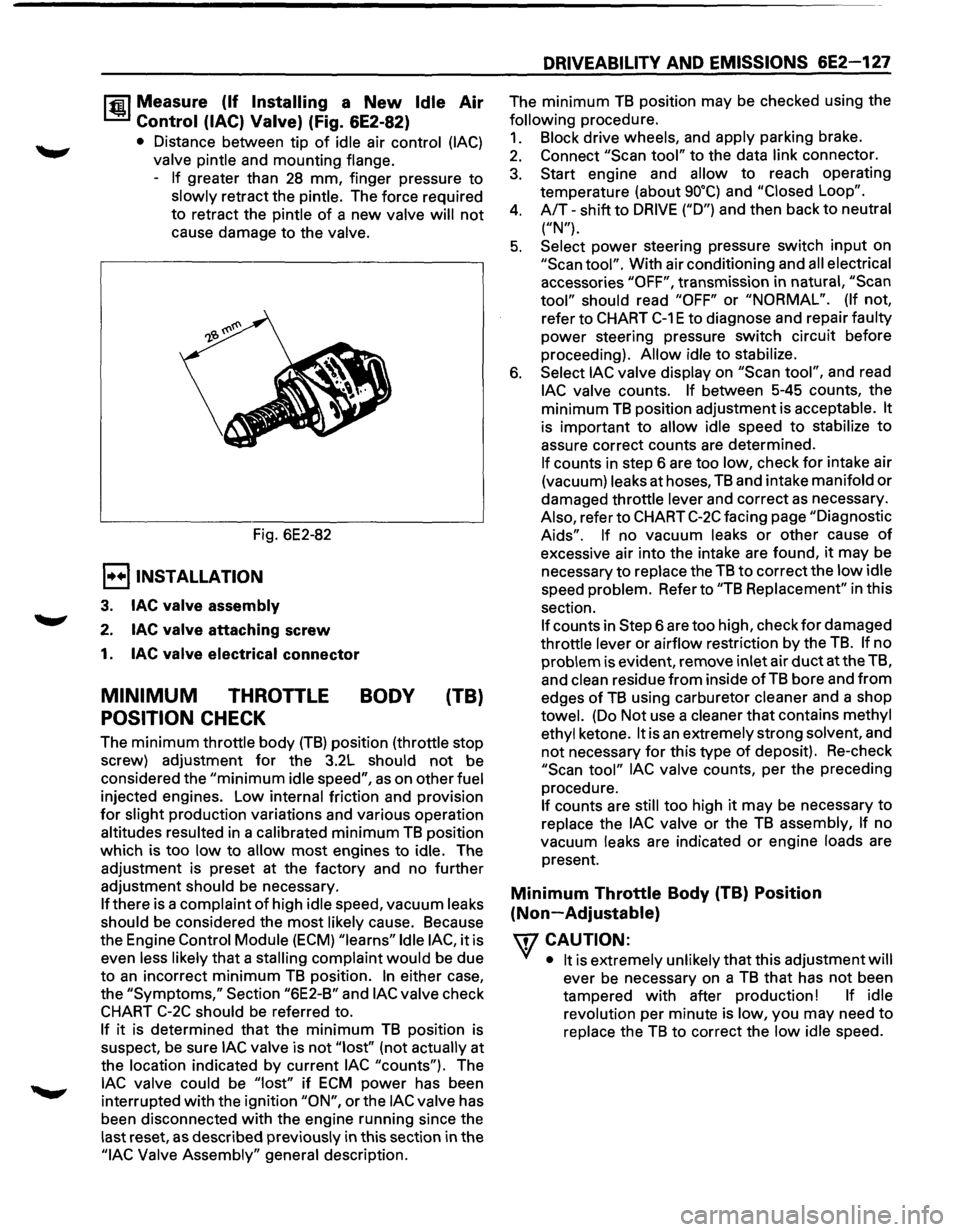
1~1 Measure (If Installing a New Idle Air
Control (lAC) Valve) (Fig. 6E2-82)
• Distance between tip of idle air control (lAC)
valve pintle and mounting flange.
-
If greater than 28 mm, finger pressure to
slowly retract the pintle. The force required
to retract the pintle
of a new valve will not
cause damage to the valve.
Fig. 6E2-82
E) INSTALLATION
3. lAC valve assembly
2. lAC valve attaching screw
1. lAC valve electrical connector
MINIMUM THROTTLE BODY (TB)
POSITION CHECK
The minimum throttle body (TB) position (throttle stop
screw) adjustment
for the 3.2L should not be
considered the
"minimum idle speed", as on other fuel
injected engines. Low internal friction and provision
for slight production variations and various operation
altitudes resulted in a calibrated
minimum TB position
which is too
low to allow most engines to idle. The
adjustment is preset at the factory and no further
adjustment should be necessary.
If there is a complaint of high idle speed, vacuum leaks
should be considered the
most likely cause. Because
the Engine
Control Module (ECM) "learns" Idle lAC, it is
even less likely
that a stalling complaint would be due
to
an incorrect minimum TB position. In either case,
the
"Symptoms," Section "6E2-B" and lAC valve check
CHART C-2C should be referred to.
If it is determined that the minimum TB position is
suspect,
be sure lAC valve is not "lost'' (not actually at
the location indicated by current
lAC "counts"). The
lAC valve could be "lost" if ECM power has been
interrupted
with the ignition "ON", or the lAC valve has
been disconnected
with the engine running since the
last reset,
as described previously in this section in the
"lAC Valve Assembly" general description.
DRIVEABILITY AND EMISSIONS 6E2-127
The minimum TB position may be checked using the
following procedure.
1. Block drive wheels, and apply parking brake.
2. Connect "Scan tool" to the data link connector.
3. Start engine and allow to reach operating
temperature (about
go•q and "Closed Loop".
4. A/T-shift to DRIVE ("D") and then back to neutral
("N").
5. Select power steering pressure switch input on
"Scan tool". With air conditioning and all electrical
accessories
"OFF", transmission in natural, "Scan
tool" should read "OFF" or "NORMAL". (If not,
refer to
CHART C-1 E to diagnose and repair faulty
power steering pressure switch circuit before
proceeding).
Allow idle to stabilize.
6. Select lAC valve display on "Scan tool", and read
lAC valve counts. If between 5-45 counts, the
minimum
TB position adjustment is acceptable. It
is important to allow idle speed to stabilize to
assure correct counts are determined.
If counts in step 6 are too low, check for intake air
(vacuum) leaks at hoses,
TB and intake manifold or
damaged throttle lever and correct as necessary.
Also, refer to
CHART C-2C facing page "Diagnostic
Aids". If no vacuum leaks or other cause of
excessive air into the intake are found, it may be
necessary
to replace the TB to correct the low idle
speed problem. Refer to
"TB Replacement" in this
section.
If counts in Step 6 are too high, check for damaged
throttle lever or airflow restriction by the
TB. If no
problem is evident, remove inlet air
duct at the TB,
and
clean residue from inside of TB bore and from
edges of TB using carburetor cleaner and a shop
towel. (Do Not use a cleaner that contains methyl
ethyl ketone.
It is an extremely strong solvent, and
not necessary for this type of deposit). Re-check
"Scan tool" lAC valve counts, per the preceding
procedure.
If counts are still too high it may be necessary to
replace the
lAC valve or the TB assembly, If no
vacuum leaks are indicated
or engine loads are
present.
Minimum Throttle Body (TB) Position
(Non-Adjustable)
\fl CAUTION:
VI • It is extremely unlikely that this adjustment will
ever be necessary on a TB that has not been
tampered
with after production! If idle
revolution per minute is low, you may need
to
replace the TB to correct the low idle speed.