oil ISUZU TROOPER 1995 Workshop Manual
[x] Cancel search | Manufacturer: ISUZU, Model Year: 1995, Model line: TROOPER, Model: ISUZU TROOPER 1995Pages: 1928
Page 663 of 1928
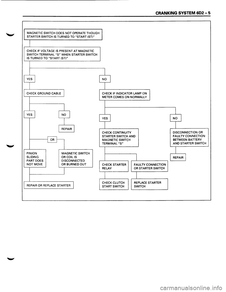
CRANKING SYSTEM 602-5
MAGNETIC SWITCH DOES NOT OPERATE THOUGH STARTER SWITCH IS TURNED TO "START (ST)"
CHECK IF VOLTAGE IS PRESENT AT MAGNETIC
SWITCH TERMINAL "S" WHEN STARTER SWITCH
IS TURNED TO "START (ST)"
YES
I NO I
CHECK GROUND CABLE I CHECK IF INDICATOR LAMP ON METER COMES ON NORMALLY
I
I
YES I NO I YES I I I
NO
I REPAIR I CHECK CONTINUITY DISCONNECTION OR
STARTER SWITCH AND FAULTY CONNECTION
OR MAGNETIC
SWITCH BETWEEN BATTERY
TERMINAL "S" AND STARTER SWITCH
I PINION
MAGNETIC SWITCH
SLIDING
OR COIL IS I REPAIR I PART DOES DISCONNECTED NOT MOVE OR BURNED OUT CHECK STARTER FAULTY CONNECTION
I
RELAY OR STARTER SWITCH
I
REPAIR OR REPLACE STARTER I CHECK CLUTCH REPLACE STARTER
START SWITCH SWITCH
Page 664 of 1928
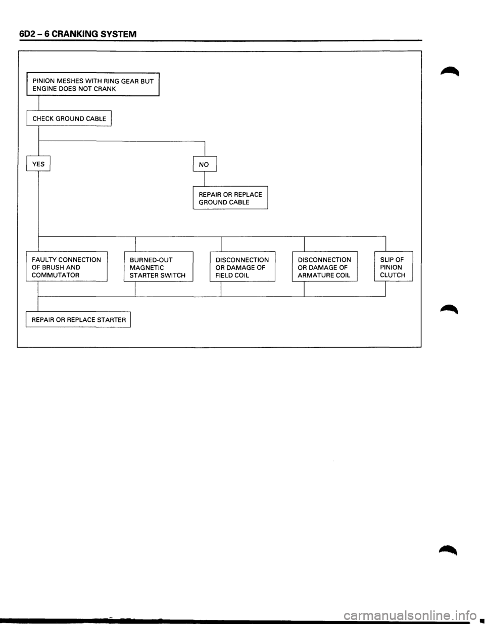
602-6 CRANKING SYSTEM
PINION MESHES WITH RING GEAR BUT ENGINE DOES NOT CRANK
CHECK
GROUND CABLE I
I
YES I NO I
I
REPAIR OR REPLACE I GROUND CABLE
I I I I
FAULTY CONNECTION BURNED-OUT DISCONNECTION DISCONNECTION SLIP OF OF BRUSH AND MAGNETIC OR DAMAGE OF OR DAMAGE OF PINION COMMUTATOR STARTER
SWITCH FIELD COIL ARMATURE COIL CLUTCH
I I I J
REPAIR OR REPLACE STARTER I
•
Page 672 of 1928
602-14 CRANKING SYSTEM
Fig. 602-23
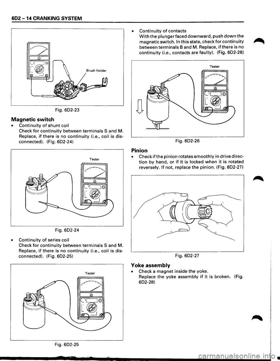
Magnetic switch
• Continuity of shunt coil
Check for continuity between terminals S and M.
Replace, if there is no continuity (i.e., coil is dis
connected). (Fig. 602-24)
Tester
Fig. 602-24
• Continuity of series coil
Check for continuity between terminals S and M.
Replace, if there is no continuity (i.e., coil is dis
connected). (Fig. 602-25)
Tester
Fig. 602-25
• Continuity of contacts
With the plunger faced downward, push down the
magnetic switch. In this state, check for continuity ~
between terminals Band M. Replace, if there is no
continuity (i.e., contacts are faulty). (Fig. 602-26)
Tester
Fig. 602-26
Pinion
• Check ifthe pinion rotates smoothly in drive direc
tion by hand, or if it is locked when it is rotated
reversely.
If not, replace the pinion. (Fig. 602-27)
Fig. 602-27
Yoke assembly
• Check a magnet inside the yoke.
Replace the yoke assembly if it is broken. (Fig.
602-28)
•
Page 677 of 1928
CHARGING SYSTEM 6D3-1
SECTION 603
CHARGING SYSTEM
CONTENTS
General Description ....................... .
Diagnosis
.................................... .
On-Vehicle Service ........................ . 6D3-1
6D3-3
6D3-4 Unit
Repair . . .. .. . . . . . . . . . . . . .. . . . . . . . . . . . . . . . 6D3-6
Inspection and Repair . . . . . . . . . . . . . . . . . . 6D3-8
Main Data and Specifications............ 6D3-12
GENERAL DESCRIPTION
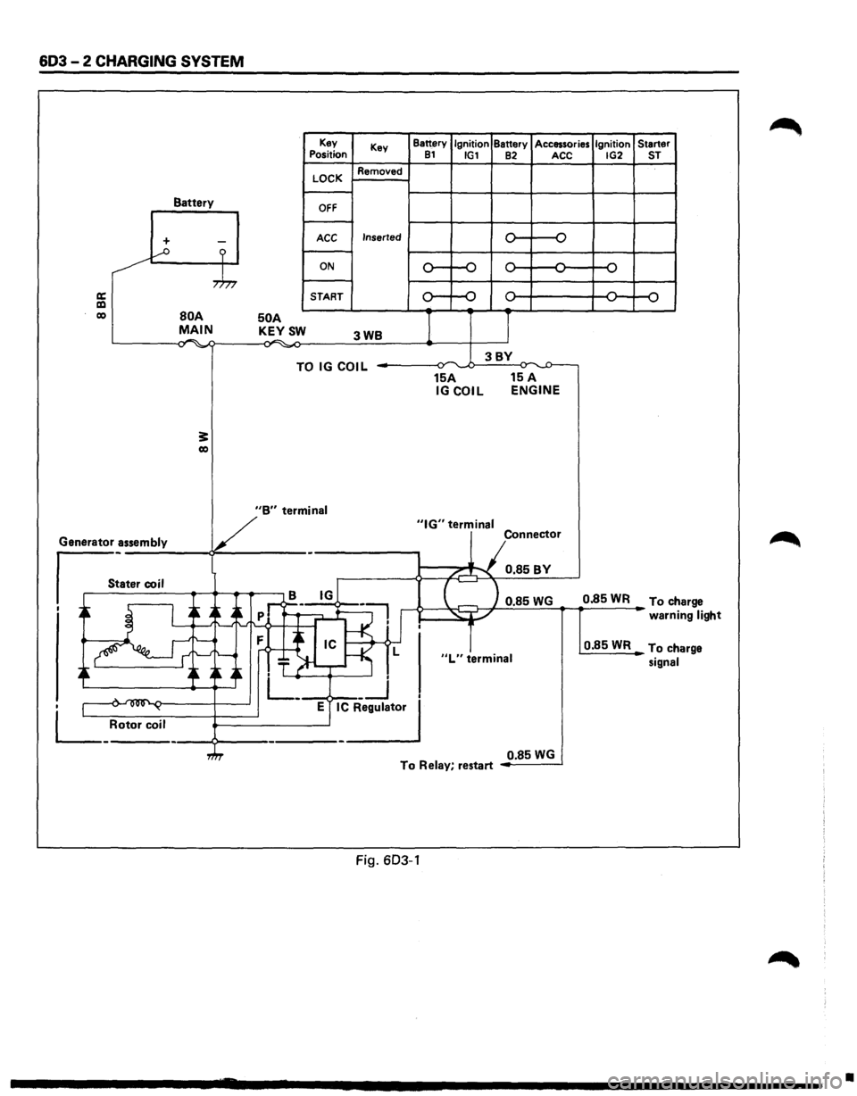
The charging system is the IC integral regulator charg
ing system and its main components are connected as
shown in Fig. 6D3-1.
The regulator is a solid state
type and it is mounted
along with the brush holder assembly inside the
generator installed on the rear end cover. The
generator does not require particular mainte
nance such
as voltage adjustment. The rectifier con
nected
to the stator coil has eight diodes to transform
A.C. voltage into D.C. voltage. This D.C. voltage is
connected
to the output terminal of generator. (Fig.
6D3-1)
Page 678 of 1928
603-2 CHARGING SYSTEM
Battery
+ -...--o ?
,.h,
a: a:l co BOA MAIN . .-. -,., ~
3: co
50 A KEYSW
Key
Position
LOCK
OFF
ACC
ON
START Key
Removed
Inserted
3WB
TO IG COIL
Battery Ignition Battery Accessories Ignition Starter 81 IG1 82 ACC IG2 ST
0 -o
,.... ,....
,.... ,... ,.... ...., ...., ...., ...., ....,
0 ,.... ,.... ,.... 0 ....,
...., ....,
I J
3BY ~ ,.,.
15A 15 A IGCOIL ENGINE
V
"B" termin_a_I _____ _,"IG" terminal
Generator assembly
s_:a_t_er_co __ i_l __ ~~~.-.-~ - Connector
/...-"""\. 0.85BY
B IG
I ~ I ~ A~
-~ ..->--~~ 0.85 WG 0.85 WR To ch arge
' _-: .~:f--<·1'
.~ ~ ~~~~ T ~-r-~ L
. L_ __j
• 1 .... ~ ~ E IC Regulator
L_ Rotor coil ----9---------------'
"L" terminal
warni ng light
0.85WR To ch arge
signal
0.85
WG To Relay, restart
Fig. 603-1
•
Page 685 of 1928
CHARGING SYSTEM 603 - 9
Fig. 603-19
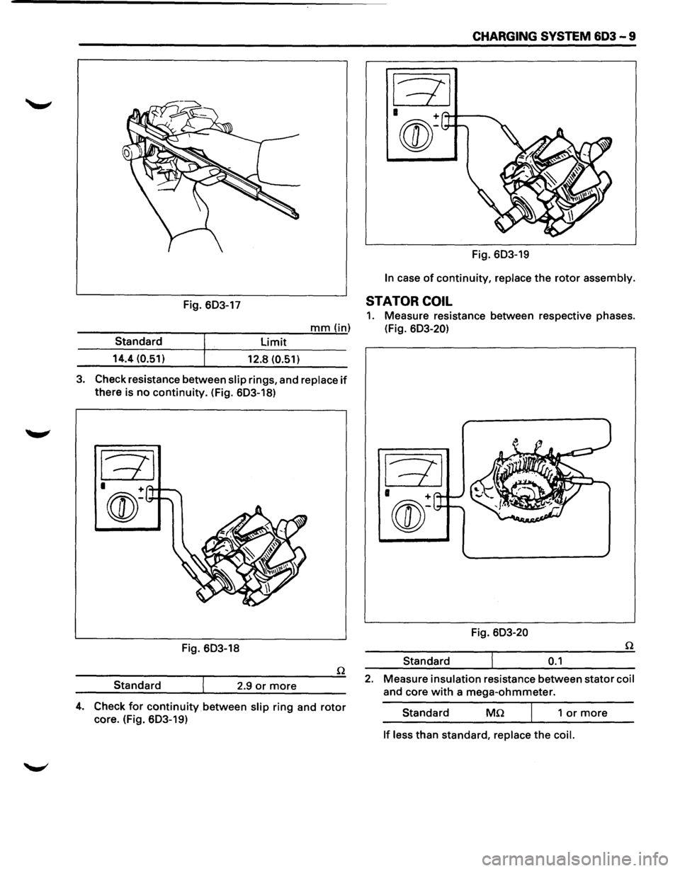
In case of continuity, replace the rotor assembly.
Fig. 603-17 STATOR COIL
1. Measure resistance between respective phases.
---------r-----:-:--:---'m;.;..;.;...;.m""'"(.....,..in) (Fig. 603-20)
limit Standard
14.4 (0.51)
12.8 (0.51)
3. Check resistance between slip rings, and replace if
there is no continuity. (Fig. 603-18)
Fig. 603-18
Standard 2.9
or more
4. Check for continuity between slip ring and rotor
core. (Fig. 603-19) Fig.
603-20
Standard
0.1
2. Measure insulation resistance between stator coil
and core with a mega-ohmmeter.
Standard
Mn 1 or more
If less than standard, replace the coil.
Page 689 of 1928
IGNITION SYSTEM 6D4 - 1
SECTION 604
IGNITION SYSTEM
CONTENTS
General Description ...................... .
Diagnosis
................................... .
On-Vehicle Service ....................... .
Spark Plug Wire ....................... .
Spark Plug .............................. . 6D4-1
6D4-2 6D4-3
6D4-3
6D4-3
Electronic Ignition (EI) Assembly ...
Crankshaft Position Sensor
(CKP sensor) ........................ .
Torque Specifications
................ .
Main Data and Specifications
......... . 6D4-5
6D4-5
6D4-6
6D4-7
GENERAL DESCRIPTION
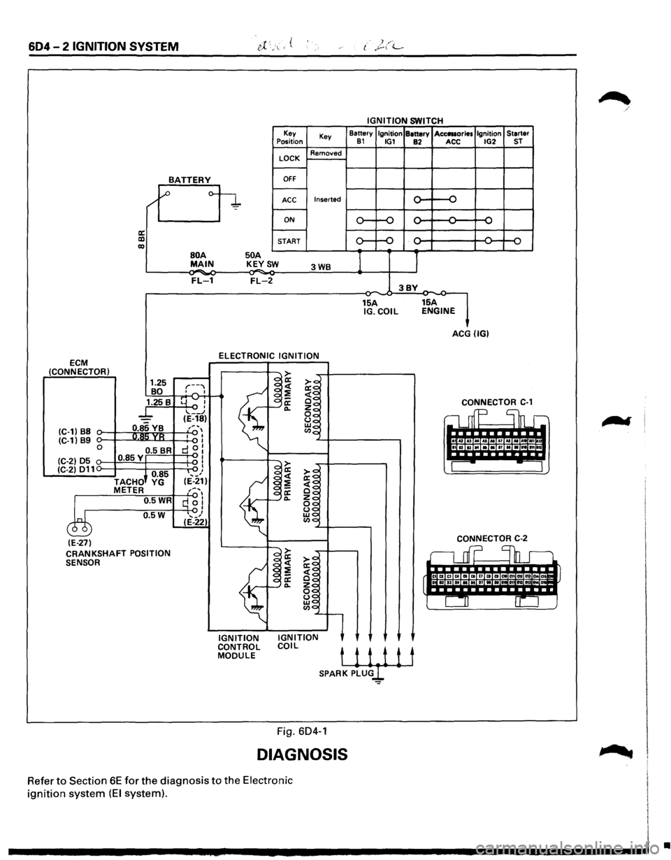
Ignition is done by the Electronic Ignition (EI) that
fires directly the ignition plugs from ignition coils
through spark plug wires without using a distributor.
A pair of ignition coils for the cylinders having differ
ent phases by 360° (No.1 and No.4, No.2 and No.5,
No.3 and No.6) are
fired simultaneously.
Since the cylinder on exhaust stoke requires less
energy to fire its ignition plug, energy from the
ignition coils can be utilized to fire the mating cylin
der on compression stroke. After additional 360°
rotation, respective cylinder stokes are reversed.
TheEl consists of three ignition coils, ignition control
module, crank angle sensor, Engine Control Module
(ECM) and other components.
Module is provided under the ignition coil, connected
with ECM by means of 6-pin connector. The
ignition control module turns on/off the primary
circuit of ignition coils, and also it controls the igni
tion timing at the engine
speed below 538 rpm.
A notch in
the timing disc on the crankshaft activates
the crank angle sensor which then sends information
such as firing order and starting timing of each
ignition coil to the ECM.
Further, the El employs Ignition Control (I C) to control
similar to a distributor system.
By receiving
signals such as crank position, engine
speed, water temperature and Manifold Absolute
Pressure (MAP), the ECM controls the ignition timing.
Page 690 of 1928
604-2 IGNITION SYSTEM
IGNITION SWITCH
Key
Key Battery
Ignition Battery Acc111ories Ignition
Starter Position 81 IG1 82 ACC IG2 ST
LOCK Removed
BATTERY OFF
/'1 ~ o-
~ Inserted ...... {) ACC ..., -
ON ...... ..... ...... ...... ...... ~ -.....
a: ...... -lXI START Q II) '-' '-' ...., ,_,
BOA 50 A
I 1 MAIN K~YSW 3WB
FL-1 FL-2 3BY -15A 15A IG.COIL ENGINE
ACG (IG)
ELECTRONIC
IGNITION ECM (CONNECTOR) > 1.25 r--""
~~ ~~ BO o""' I
~
1.25 B rrvl -~~ ' f"--~ CONNECTOR C-1
_l_ .... __ .J ~~ c1 mp Shr (E-18)
(C-1) B8 0.85 VB ,, ... , ~~ R!'i YR I I Cl.lo
I !ita lui (C-1) 89 I 0 0.5 BR d 0: IBIBIIIINIBI111Io
(C-2) 05 0.85Y "'I I I > ---(C-2) 011 I
I
)+ 0.85 '-'I a:
~~ ,_, <( TACHO YG (E-21)
~
;;!] METER ,:. .... , a: ~~ 0.5WR q 0! 0... ~~
0.5W I ~$ ... _, ~0 c ( (E-22)
(E-27) CONNECTOR C-2
CRANKSHAFT POSITION .::::> rL
r;::::l enD. .-SENSOR I~ ~~
~ ~ ~~ rt~·· IC4 IT>TiiTiil
f §~
~g l CIJ 0::
·~'l
IGNITION IGNITION CONTROL
COIL MODULE tii1it SPARK PLU
DIAGNOSIS
Refer to Section 6E for the diagnosis to the Electronic
ignition system (EI system).
•
Page 691 of 1928
![ISUZU TROOPER 1995 Workshop Manual IGNITION SYSTEM 604 - 3
ON-VEHICLE SERVICE
SPARK PLUG WIRES
EJ REMOVAL
Preparation
• Disconnect battery ground cable.
1. Spark plug wires (Fig. 604-2)
Fig. 6D4-2
(1!] INSPECTION AND REPAIR](/img/61/57183/w960_57183-690.png "ISUZU TROOPER 1995 Workshop Manual IGNITION SYSTEM 604 - 3
ON-VEHICLE SERVICE
SPARK PLUG WIRES
EJ REMOVAL
Preparation
• Disconnect battery ground cable.
1. Spark plug wires (Fig. 604-2)
Fig. 6D4-2
(1!] INSPECTION AND REPAIR")
IGNITION SYSTEM 604 - 3
ON-VEHICLE SERVICE
SPARK PLUG WIRES
EJ REMOVAL
Preparation
• Disconnect battery ground cable.
1. Spark plug wires (Fig. 604-2)
Fig. 6D4-2
(1!] INSPECTION AND REPAIR
Check the high tension cable for insulation. Check
terminals for corrosion or damage, and replace as
necessary.
Measuring resistance of spark plug wires (kQ)
Spare plug wires SOHC DOHC
No.1 cable 6.4-14.9 6.2-14.2
No.2 cable 5.7-13.1 7.2-16.7
No.3 cable 6.2-14.4 6.5-14.9
No.4 cable 5.8-13.3 6.8-15.8
No.5 cable 6.4-14.9 6.9-16.0
No.6 cable 6.9-16.0 6.3-14.5
Measure resistance
of spark plug wires, and replace
the cable if its value exceeds the standard. (Fig. 6D4-
3)
Fig. 6D4-3
B INSTALLATION
1. Spark plug wires
• Connect ignition coils and spark plugs with
spark plug wires respectively. Match each
number (cylinder No.) marked on the ignition
coil with that on spark plug wire, and connect
each spark
plug for the cylinder. (Fig. 6D4-4)
LH bank
y Front
#4-
#1--
1®®®1
RH Bank
Connecting Position of Spark plug wire
Fig. 6D4-4
• Connect battery ground cable.
"f CAUTION
Do not cross, twist or pull the spark plug wires.
SPARK PLUG
EJ REMOVAL
1. Spare plug wires
2. Spark plugs (Fig. 604-5)
Page 692 of 1928
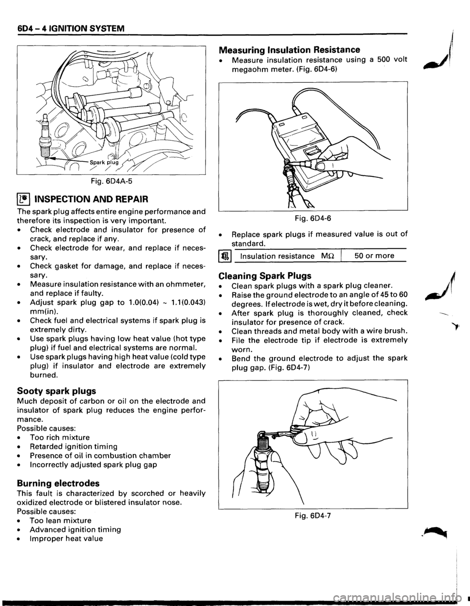
604-4 IGNITION SYSTEM
Fig. 604A-5
~ INSPECTION AND REPAIR
The spark plug affects entire engine performance and
therefore its inspection is very important.
• Check electrode and insulator for presence of
crack, and replace if any.
• Check electrode for wear, and replace if neces
sary.
• Check gasket for damage, and replace if neces
sary.
• Measure insulation resistance with an ohmmeter,
and replace if faulty.
• Adjust spark plug gap to 1.0(0.04) -1.1 (0.043)
mm(in).
• Check fuel and electrical systems if spark plug is
extremely dirty.
• Use spark plugs having low heat value (hot type
plug) if fuel and electrical systems are normal.
• Use spark plugs having high heat value (cold type
plug) if insulator and electrode are extremely
burned.
Sooty spark plugs
Much deposit of carbon or oil on the electrode and
insulator of spark plug reduces the engine perfor
mance.
Possible causes:
• Too rich mixture
• Retarded ignition timing
• Presence of oil in combustion chamber
• Incorrectly adjusted spark plug gap
Burning electrodes
This fault is characterized by scorched or heavily
oxidized electrode or blistered insulator nose.
Possible causes:
• Too lean mixture
• Advanced ignition timing
• Improper heat value
Measuring Insulation Resistance
• Measure insulation resistance using a 500 volt
megaohm meter. (Fig. 604-6)
Fig.
604-6
• Replace spark plugs if measured value is out of
standard.
I @!.j Insulation resistance MQ 50 or more
Cleaning Spark Plugs
• Clean spark plugs with a spark plug cleaner.
• Raise the ground electrode to an angle of 45 to 60
degrees. If electrode is wet, dry it before cleaning.
• After spark plug is thoroughly cleaned, check
insulator for presence of crack.
• Clean threads and metal body with a wire brush.
• File the electrode tip if electrode is extremely
worn.
• Bend the ground electrode to adjust the spark
plug gap. (Fig. 604-7)
Fig. 604-7
•