oil ISUZU TROOPER 1995 Workshop Manual
[x] Cancel search | Manufacturer: ISUZU, Model Year: 1995, Model line: TROOPER, Model: ISUZU TROOPER 1995Pages: 1928
Page 614 of 1928
 ~-;_' ;_\
~: PISTON, PISTON RINGS AND CONNECTING ROD
5
6
2
Removal steps 1. Cylinder head
2. Oil pan
3. Oil pipe and rubber ring
4. Oil strainer an")
6A 1-56 ENGINE (V6 3.2L DOHC AND SOHC) ~-;_' ;_\'
~: PISTON, PISTON RINGS AND CONNECTING ROD
5
6
2
Removal steps 1. Cylinder head
2. Oil pan
3. Oil pipe and rubber ring
4. Oil strainer and rubber ring
5.
Oil gallery
6. Piston
and connecting rod assembly
Installation steps
To install, follow the removal
steps in the reverse order.
Fig. 6A1-68
1••1 REMOVAL
1. Cylinder head
• See "Cylinder Head Removal and Installation".
2. Oil pan
• See "Oil Pan Removal and Installation".
3. Oil pipe and rubber ring
4. Oil strainer and rubber ring
5.
Oil gallery
6. Piston and connecting rod assembly
• Before removing the bearing cap, remove
carbon on the top
of cylinder bore.
• Push piston and connecting rod out from the
top of cylinder bore.
1••1 INSTALLATION
6. Piston and connecting rod assembly
19:::7;1• Apply engine oil to cylinder bore, connecting
rod bearings and crank pins.
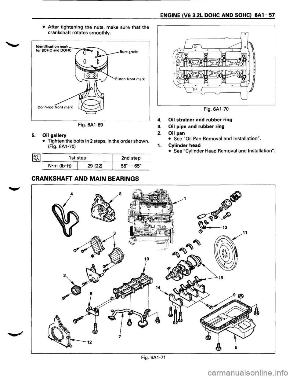
• When installing the piston, its front mark must
face the engine front side. (Fig. 6A 1-69)
• The bearing cap number must be same as
connecting rod number.
1~1 • Apply engine oil to the thread and sealing
surface
of each nut.
~~~· Tighten nuts to the specified torque.
Torque
N·m (lb·ft) 54 (40)
NOTE:
• Do not apply engine oil to the bearing back
faces and connecting rod bearing fitting
surfaces.
•
Page 615 of 1928
5.
• After tightening the nuts, make sure that the
crankshaft rotates
smoothly.
Bore g,rade
Fig. 6A1-69
Oil gallery
• Tighten the bolts in 2 steps, in the order shown.
(Fig. 6A1-70)
1~1 _________ 1_st_s,t_e~p ________ ~_2_n_d_s_t_ep~---
N·m (lb·ft) 29 (22) ss·-ss·
CRANKSHAFT AND MAIN BEARINGS
~·
3
7
ENGINE (V6 3.2L DOHC AND SOHC) 6A 1-57
4.
3.
2.
1.
Fig. 6A1-70
Oil strainer and rubber ring
Oil pipe and rubber ring
Oil pan
• See "Oil Pan Removal and Installation".
Cylinder head
• See "Cylinder Head Removal and Installation".
11
15
5
Fig. 6A1-71
Page 616 of 1928
,): .. • T·
6A 1-58 ENGINE (V6 3.2L DOHC AND SOHC)
EJ REMOVAL
1. Engine assembly
• See "Engine Assembly
Removal and Instal-
lation".
2. Crankshaft pulley
3. Timing belt cover
4. Timing belt
5. Oil pan
6. Oil pipe and rubber ring
7. Oil strainer and rubber ring
8. Oil pump assembly
9. Crankcase side bolts
10.
Oil gallery
11. Flywheel
12.
Rear oil seal retainers
13.
Connecting rod caps
14.
Crankshaft main bearing caps
15.
Crankshaft and main bearings
1•+1 INSTALLATION
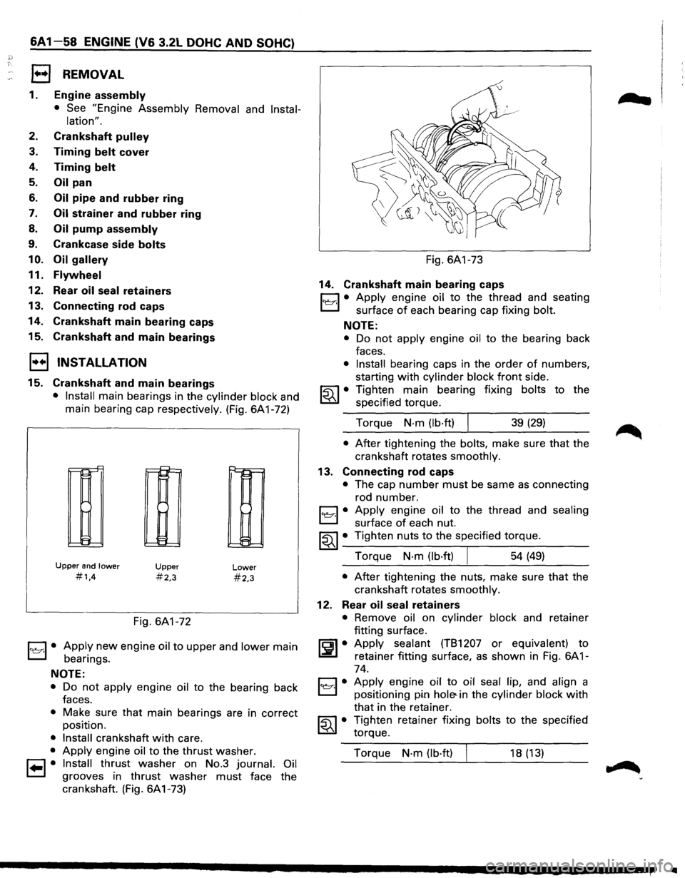
15. Crankshaft and main bearings
• Install main bearings in the cylinder block and
main bearing cap respectively. (Fig. 6A1-72)
r-r-'
II-
!:=
Upper and lower
#1,4
~
!::
E:
Upper
#2,3
Fig. 6A1-72
Lower
#2,3
1~1· Apply new engine oil to upper and lower main
bearings.
NOTE:
• Do not apply engine oil to the bearing back
faces.
• Make sure that main bearings are in correct
position.
• Install crankshaft with care.
• Apply engine oil to the thrust washer.
1•1• Install thrust washer on No.3 journal. Oil
grooves in thrust washer must face the
crankshaft. (Fig. 6A1-73) Fig.
6A1-73
14. Crankshaft main bearing caps
C1 • Apply engine oil to the thread and seating
L:::J surface of each bearing cap fixing bolt.
NOTE:
• Do not apply engine oil to the bearing back
faces.
• Install bearing caps in the order of numbers,
starting
with cylinder block front side.
~~~ • Tighten main bearing fixing bolts to the
specified torque.
Torque
N·m (lb·ft) I 39 (29)
• After tightening the bolts, make sure that the
crankshaft rotates
smoothly.
13. Connecting rod caps
• The cap number must be same as connecting
rod number.
1~1· Apply engine oil to the thread and sealing
surface of each nut.
~~~· Tighten nuts to the specified torque.
Torque
N·m (lb·ft) 54 (49)
• After tightening the nuts, make sure that the
crankshaft rotates
smoothly.
12. Rear oil seal retainers
• Remove oil on cylinder block and retainer
fitting surface.
~~~· Apply sealant (TB1207 or equivalent) to
retainer fitting surface, as shown in Fig. 6A 1-
74.
C1 • Apply engine oil to oil seal lip, and align a
El positioning pin hole< in the cylinder block with
that in the retainer.
~~~· Tighten retainer fixing bolts to the specified
torque.
Torque
N·m (lb·ft) 18 (13)
IIIII
Page 617 of 1928
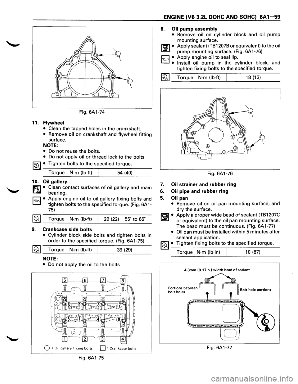
Fig. 6A1-74
11. Flywheel
• Clean the tapped holes in the crankshaft.
• Remove oil on crankshaft and flywheel fitting
surface.
NOTE:
• Do not reuse the bolts.
•
Do not apply oil or thread lock to the bolts.
~~~ • Tighten bolts to the specified torque.
Torque
N-m (lb·ft) 54 (40)
10. Oil gallery
m • Clean contact surfaces of oil gallery and main
~ bearing.
D • Apply engine oil to oil gallery fixing bolts and
L:::J tighten bolts to the specified torque. (Fig. 6A 1-
75)
~~~ Torque N·m (lb·ft) 29 (22) -55° to 65°
9. Crankcase side bolts
• Cylinder block side bolts and tighten bolts in
order
to the specified torque. (Fig. 6A 1-75)
~~~ Torque N·m (lb·ft) 39 (29)
NOTE:
• Do not apply the oil to the bolts
0 :Oil gallery fixing bolts 0: Crankcase bolts
Fig. 6A1-75
ENGINE (V6 3.2L DOHC AND SOHC) 6A1-59
8. Oil pump assembly
• Remove oil on cylinder block and oil pump
mounting surface.
ll:JI• Apply sealant (TB12078 or equivalent) to the oil
pump mounting surface. (Fig. 6A1-76)
19Y·I •. Apply engine oil to seal lip.
Install oil
pump in the cylinder block, and
tighten fixing
bolts to the specified torque.
1~1 Torque N·m (lb·ft)
Fig. 6A1-76
7. Oil strainer and rubber ring
6. Oil pipe and rubber ring
5. Oil pan
18 (13)
• Remove oil on oil pan mounting surface, and
dry the surface.
~~~· Apply a proper wide bead of sealant (TB1207C
or equivalent) to the oil pan mounting surface.
The bead
must be continuous. (Fig. 6A1-77)
• Oil pan must be installed within 5 minutes after
sealant application.
~~~· Tighten fixing bolts to the specified torque.
Torque
N·m (lb·in) 10 (87)
4.3mm (0.17in.) width bead of sealant
Portions between bolt holes I Bolt hole portions
D
Fig. 6A1-77
Page 618 of 1928
6A1-60 ENGINE (V6 3.2L DOHC AND SOHC}
4. Timing belt
• See "Timing Belt Removal and Installation".
3. Timing belt cover
2. Crankshaft pulley
~ • Using special tool J-8614-01, hold the
~ crankshaft pulley.
~~~· Tighten center bolt to the specified torque.
Torque
N·m (lb·ft) 167 (123)
1. Engine assembly
• See "Engine Assembly Removal and Instal
lation".
REAR OIL SEAL
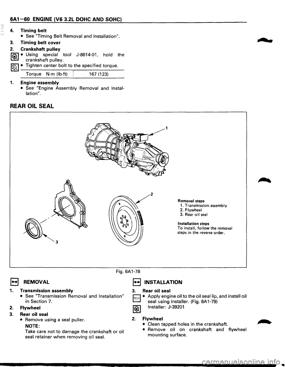
Removal steps
1. Transmission assembly
2.
Flywheel 3. Rear oil seal
Installation steps To install, follow the removal
steps in the reverse order.
Fig. 6A1-78
E) REMOVAL
1. Transmission assembly
• See "Transmission Removal and Installation"
in Section 7.
2. Flywheel
3. Rear oil seal
•
Remove using a seal puller.
NOTE:
Take care
not to damage the crankshaft or oil
seal retainer
when removing oil seal.
1••1 INSTALLATION
3. Rear oil seal
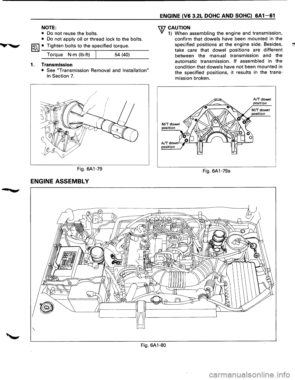
C1 • Apply engine oil to the oil seal lip, and install oil
L:::l seal using installer. (Fig. 6A 1-79)
1®1 Installer: J-39201
2. Flywheel
• Clean tapped holes in the crankshaft.
• Remove oil on crankshaft and flywheel
mounting surface.
...
Page 619 of 1928
NOTE:
• Do not reuse the bolts.
•
Do not apply oil or thread lock to the bolts.
~~~ • Tighten bolts to the specified torque.
Torque
N·m (lb·ft) 54 (40)
1. Transmission
• See "Transmission Removal and Installation"
in Section 7.
Fig. 6A1-79
ENGINE ASSEMBL V
ENGINE (V6 3.2L DOHC AND SOHC) 6A 1-61
U7 CAUTION
VI 1) When assembling the engine and transmission,
confirm that
dowels have been mounted in the
specified positions at the engine side. Besides,
take care that
dowel positions are different
between the
manual transmission and the
automatic transmission.
If assembled in the
condition that
dowels have not been mounted in
the specified positions,
it results in the trans
mission broken.
M/Tdowel position
AIT dowe I Y~---...rr"lr-'1--' position
Fig. 6A1-79a
A/Tdowel position
Fig. 6A1-80
Page 621 of 1928
·-------------------------------------
ENGINE (V6 3.2L DOHC AND SOHC) 6A1-63
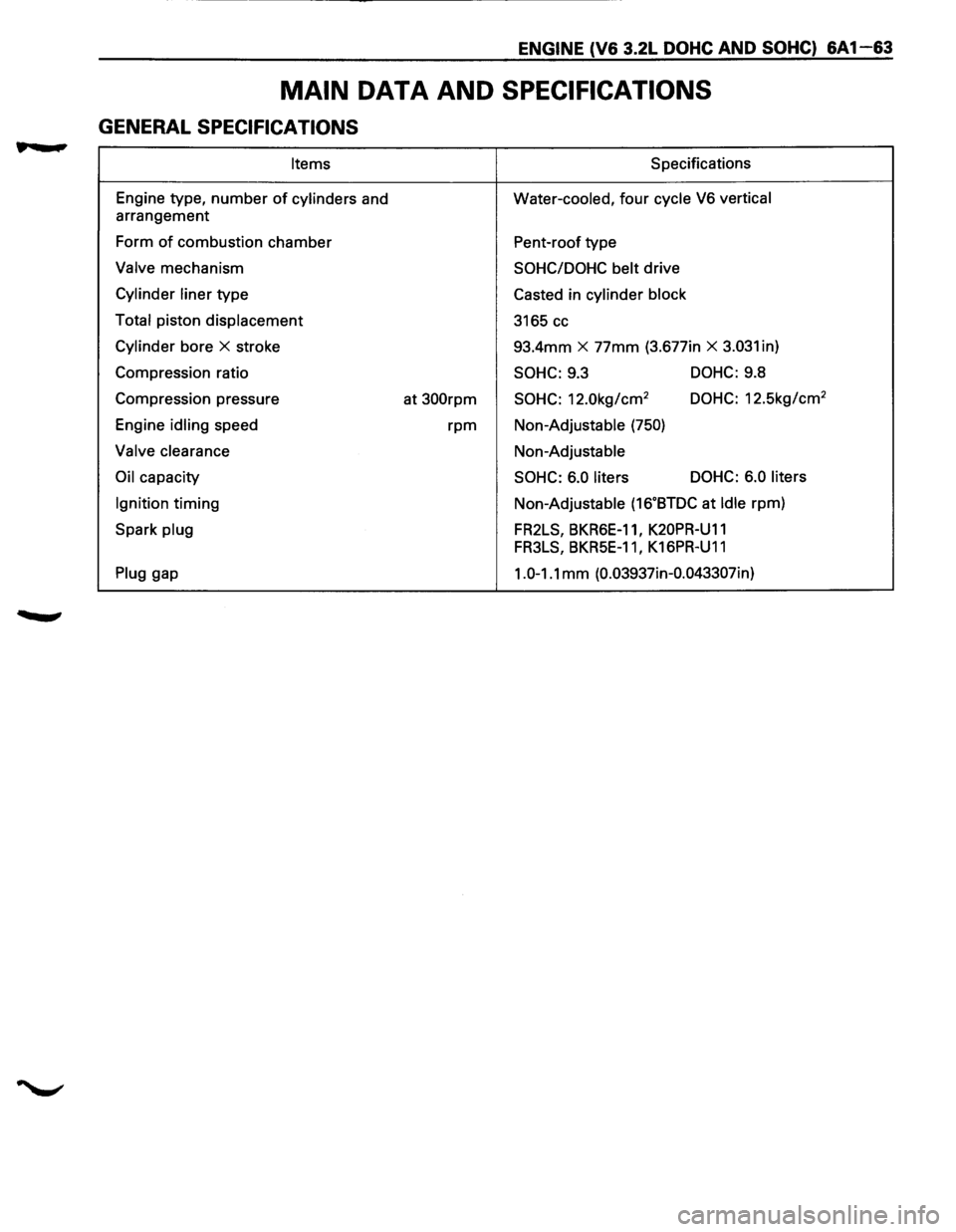
MAIN DATA AND SPECIFICATIONS
GENERAL SPECIFICATIONS
Items S pacifications
Engine type,
number of cylinders and Water-cooled, four cycle V6 vertical
arrangement
Form
of combustion chamber
Pent-roof type
Valve mechanism SOHC/DOHC belt drive
Cylinder liner type
Casted in cylinder block
Total
piston displacement
3165 cc
Cylinder bore X stroke 93.4mm X 77mm (3.677in X 3.031 in)
Compression ratio
SOHC: 9.3 DOHC: 9.8
Compression pressure
at
300rpm SOHC: 12.0kg/cm2 DOHC: 12.5kg/cm2
Engine idling speed rpm Non-Adjustable (750)
Valve clearance Non-Adjustable
Oil capacity SOHC: 6.0 liters DOHC:
6.0 liters
Ignition
timing Non-Adjustable (16.BTDC at Idle rpm)
Spark
plug FR2LS, BKR6E-11, K20PR-U11
FR3LS, BKR5E-11 I K16PR-U11
Plug gap 1.0-1.1 mm (0.03937in-0.043307in)
Page 627 of 1928
ENGINE (V6 3.2L DOHC AND SOHC) 6A1-69
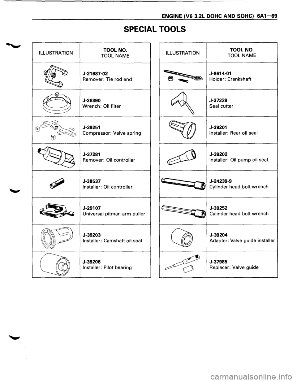
SPECIAL TOOLS
ILLUSTRATION TOOL NO.
TOOL NAME ILLUSTRATION TOOL NO.
TOOL NAME
~
J-21687-02
Remover: Tie rod end ~
J-8614-01
Holder: Crankshaft
0
J-36390
Wrench: Oil filter
~
J-37228
Seal cutter
~~
J-39251
Compressor: Valve spring
~ ~
J-39201
Installer:
Rear oil seal
~
J-37281
Remover:
Oil controller ~
J-39202
Installer: Oil
pump oil seal
~
J-38537
Installer: Oil controller
~
~
J-24239-9
Cylinder head bolt wrench
~
J-29107
Universal pitman arm puller ~
J-39252
Cylinder head bolt wrench
~
J-39203
Installer:
Camshaft oil seal Q co
J-39204
Adapter: Valve guide installer
Qg
J-39206 Installer: Pilot
bearing 4
J-37985
Replacer: Valve guide
Page 629 of 1928
ENGINE COOLING 68-1
SECTION 68
ENGINE COOLING
CONTENTS
General Description . . . . . . . . . . . . . . . . . . . . . . . . . . 68-1 Radiator . . . . . . . . . . . . . . . . . . . . . . . . . . . . . . . . . . . . . . 68-7
Diagnosis........................................ 68-3 Drive Belt Adjustment . . . . . . . . . . . . . . . . . . . . 68-1 0
On-Vehicle Service............................ 68-4 Main Data and Specifications .............. 68-12
Water Pump . . . . . . . . . . . . . . . . . . . . . . . . . . . . . . . . 68-4
Thermostat . . . . . . . . . . . . . . . . . . . . . . . . . . . . . . . . . . 68-6
Torque Specifications .................... 68-12
Special Tools ................................... 68-13
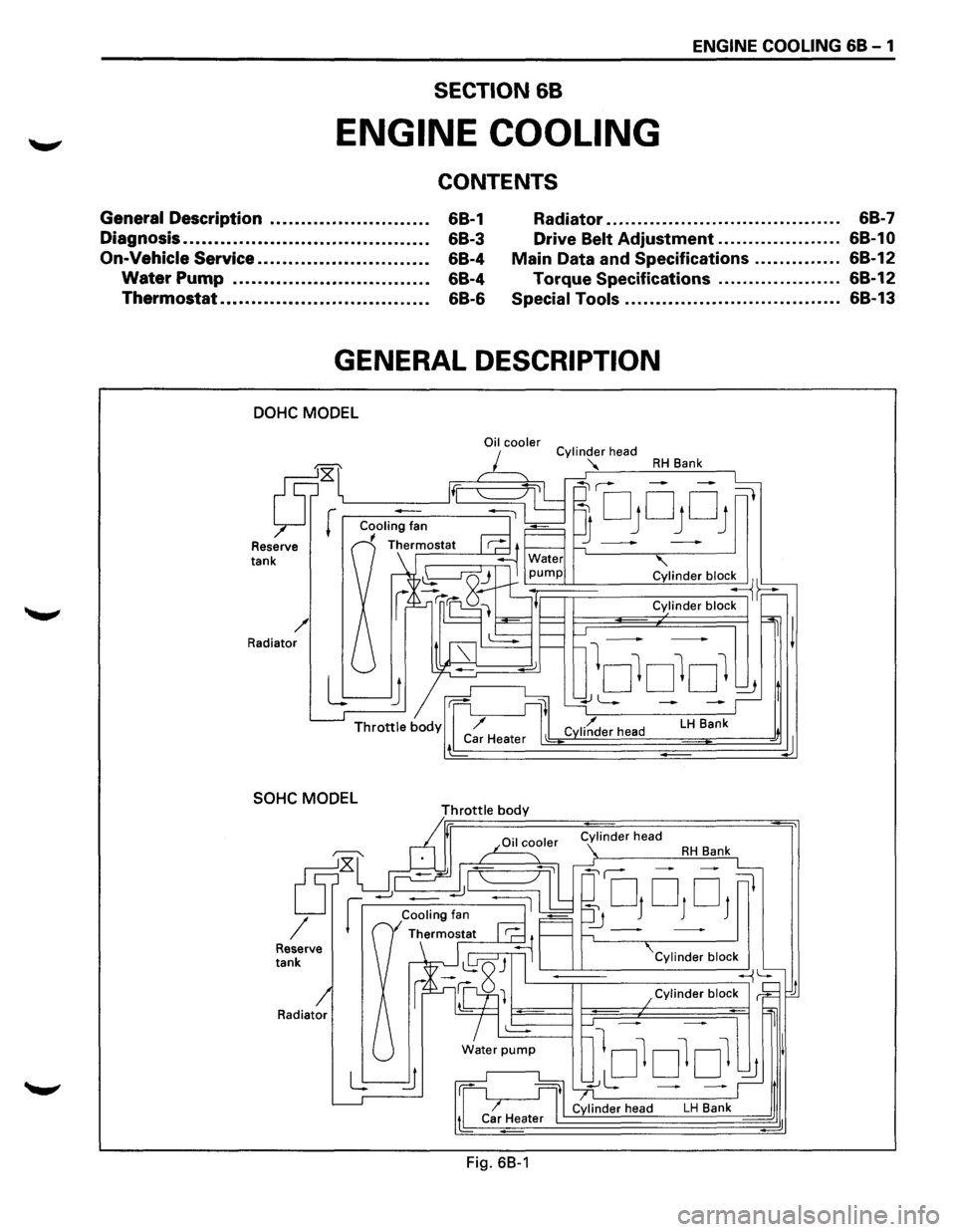
GENERAL DESCRIPTION
DOHC MODEL
Reserve tank
/ Radiator
SOHC MODEL
Radiator
Oil cooler
Throttle body
Fig. 68-1
Cylinder head
"'
RH Bank
' Cylinder bloc~~
Cylinder block
LH Bank
Cylinder block
~
lololol ~ I
~L: - -~,t
Cylinder head LH Bank d
d
Page 630 of 1928
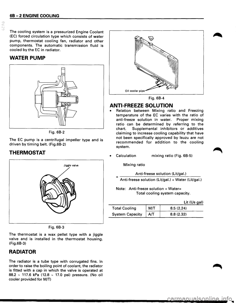
68 - 2 ENGINE COOLING
The cooling system is a pressurized Engine Coolant
(EC) forced circulation type which consists of water
pump, thermostat cooling fan, radiator and other
components. The automatic transmission fluid is
cooled by the EC in radiator.
WATER PUMP
Fig. 68-2
The
EC pump is a centrifugal impeller type and is
driven by timing belt. (Fig.68-2)
THERMOSTAT
Jiggle valve
Fig. 68-3
The
thermostat is a wax pellet type with a jiggle
valve and is installed in the thermostat housing.
(Fig.68-3)
RADIATOR
The radiator is a tube type with corrugated fins. In
order to raise the boiling point of coolant, the radiator
is fitted
with a cap in which the valve is operated at
88.2
-117.6 kPa (12.8 - 17.0 psi) pressure. (No oil
cooler
provided for M!f)
Fig. 68-4
ANTI-FREEZE SOLUTION
•
•
Relation between Mixing ratio and Freezing
temperature
of the EC varies with the ratio of
anti-freeze solution in water. Proper mixing
ratio can be determined by referring to the
chart. Supplemental inhibitors or additives
claiming to increase cooling capability that have
not been specifically approved by lsuzu are not
recommended for addition to the cooling
system.
Calculation mixing ratio (Fig. 68-5)
Mixing ratio
Anti-freese
solution (Lit/gal.) =-----------------Anti-freese solution (Lit/gal.) +Water (Lit/gal.)
Note: Anti-freeze solution +Water=
Total cooling system capacity.
Lit (Us
gal)
Total Cooling
M!f 8.5 (2.24) ~-~~--------System Capacity AfT 8.8 (2.32)