oil ISUZU TROOPER 1995 Workshop Manual
[x] Cancel search | Manufacturer: ISUZU, Model Year: 1995, Model line: TROOPER, Model: ISUZU TROOPER 1995Pages: 1928
Page 631 of 1928
Mixing ratio(%) 0 10 20 30 40 50
~
' -10
'
1
' -30
~ -40
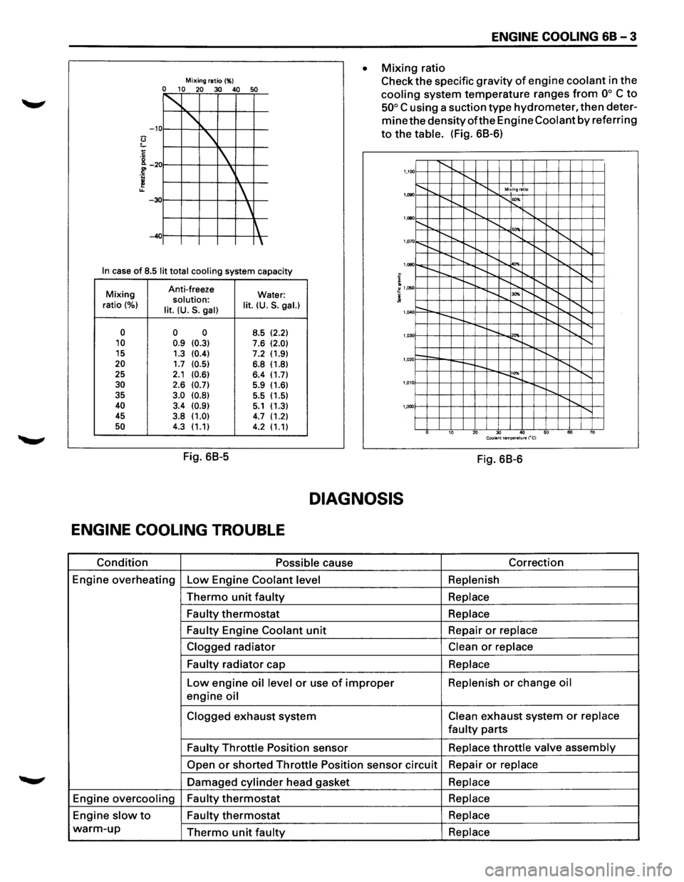
In case of 8.5 lit total cooling system capacity
Mixing Anti-freeze
Water: solution: ratio (%) lit. (U.S. gal) lit. (U.S. gal.)
0 0 0
8.5 (2.2) 10 0.9 (0.3) 7.6 (2.0) 15
1.3 (0.4) 7.2 (1.9) 20 1.7 (0.5) 6.8 (1.8)
25 2.1 (0.6) 6.4 (1.7) 30 2.6 (0.7) 5.9 (1.6)
35 3.0 (0.8) 5.5
(1.5) 40 3.4 (0.9) 5.1 (1.3)
45 3.8 (1.0) 4.7 (1.2) 50 4.3 (1.1)
4.2 (1.1)
Fig. 68-5
ENGINE COOLING 68-3
• Mixing ratio
Check
the specific gravity of engine coolant in the
cooling system temperature ranges from oo C to
50° C using a suction type hydrometer, then deter
mine the densityofthe Engine Coolant by referring
to the table. (Fig. 68-6)
1,100 1'-........ ........ ...... .............. Mixing ratio
~"""--r-... 1'-""' 1,1)90
........ ...... ........ ........ .......... '
1,000
'"" 1,07 o......_ 1'-........ I'-.......... I"-........ .......
I"-........ ..........
................. I"-........
'
1,080
....... I"-........ ~ ........ ......
........ "'" ~"""--r--..... 1,050
r-. ........ ~ .......... ......
---
........ ........ 1,040
r-.... !'--.. 1'-0 '"" ~"""--1'-.... ........ 1,03
1--....... ........ r--~ ........
'
1,020
....... ~ 1'-0 ~"""---.... 1,01
...... ,
'
1,000
10 20 30 40 50 60 70 Coolant temperature ("C)
Fig. 68-6
DIAGNOSIS
ENGINE COOLING TROUBLE
Condition Possible cause Correction
Engine
overheating Low Engine Coolant level Replenish
Thermo unit faulty Replace
Faulty
thermostat Replace
Faulty
Engine Coolant unit Repair or replace
Clogged
radiator Clean or replace
Faulty
radiator cap Replace
Low engine oil level or use of improper Replenish or change oil
engine oil
Clogged exhaust system Clean exhaust system or replace
faulty parts
Faulty Throttle Position sensor Replace throttle valve assembly
Open or shorted Throttle Position sensor circuit Repair or replace
Damaged cylinder head gasket Replace
Engine overcooling Faulty thermostat Replace
Engine slow to Faulty thermostat Replace
warm-up Thermo unit faulty Replace
Page 632 of 1928
68 - 4 ENGINE COOLING
ON-VEHICLE SERVICE
DRAINING AND REFILLING COOLING
SYSTEM
Before draining the cooling system, inspect the sys
tem and perform any necessary service to ensure that
it is clean, does not leak and is in proper working
order. The Engine Coolant (EC) level should be be
tween the "MIN" and "MAX" lines of reserve tank
when the engine is cold. If low, check for leakage and
add
EC up to the "MAX" line. There should not be any
excessive deposit of rust or scales around the radiator
cap
or radiator filler hole, and the EC should also be
free
from oil. Replace the EC if excessively dirty.
1. Completely drain the cooling system by opening
the drain petcock at the bottom of the radiator.
2. Remove the radiator cap.
W WARNING
To avoid the danger of being burned, do not
remove the cap while the engine and radiator
are still hot. Scalding fluid and steam can be
blown out under pressure.
3. Disconnect all hoses from the EC reserve tank.
Scrub and clean the inside of the reserve tank with
soap and water. Flush it well with clean water,
then drain it. Install the reserve tank and hoses.
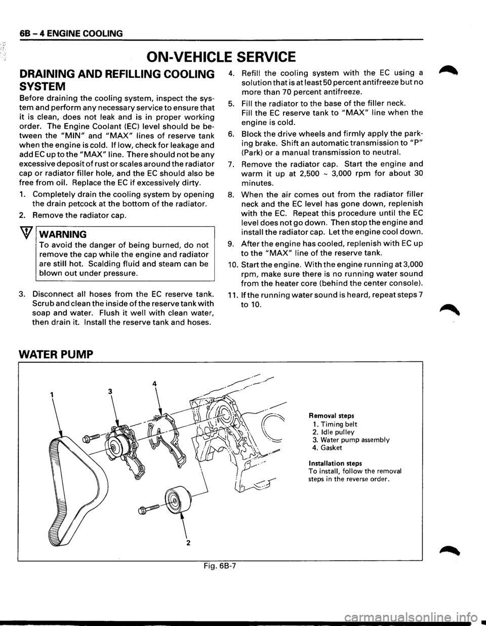
WATER PUMP
3
j
2
4. Refill the cooling system with the EC using a
solution that is at least 50 percent antifreeze but no
more than 70 percent antifreeze.
5. Fill the radiator to the base of the filler neck.
Fill the EC reserve tank to "MAX" line when the
engine is cold.
6. Block the drive wheels and firmly apply the park
ing brake.
Shift an automatic transmission to "P"
(Park) or a manual transmission to neutral.
7. Remove the radiator cap. Start the engine and
warm it up at 2,500 -3,000 rpm for about 30
minutes.
8. When the air comes out from the radiator filler
neck and the EC level has gone down, replenish
with the EC. Repeat this procedure until the EC
level does not go down. Then stop the engine and
install the radiator cap. Let the engine cool down.
9. After the engine has cooled, replenish with EC up
to the "MAX" line of the reserve tank.
10. Start the engine. With the engine running at 3,000
rpm, make sure there is no running water sound
from the heater core (behind the center console).
11. If the running water sound is heard, repeat steps 7
to 10.
Removal steps
1. Timing
belt 2. Idle pulley 3. Water pump assembly
4. Gasket
Installation steps To install, follow the removal steps in the reverse order.
Fig. 6B-7
•
Page 635 of 1928
B INSTALLATION
3. Thermostat
• Install thermostat into the thermostat hous
ing, making sure
that the jiggle valve in up
position.
2. Packing
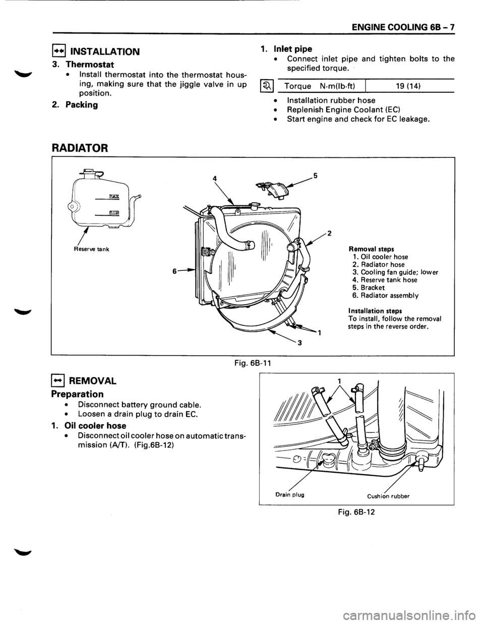
RADIATOR
Reserve tank
6
ENGINE COOLING 68-7
1. Inlet pipe
• Connect inlet pipe and tighten bolts to the
specified torque.
I~~ Torque N·mOb·ft) 19 (14)
• Installation rubber hose
• Replenish Engine Coolant (EC)
• Start engine and check for EC leakage.
2
Removal steps
1.
Oil cooler hose 2. Radiator hose
3. Cooling fan guide; lower
4. Reserve tank hose
5. Bracket
6. Radiator assembly
Installation steps
To install, follow the removal
steps in the reverse order.
Fig. 68-11
EJ REMOVAL
Preparation
• Disconnect battery ground cable.
•
Loosen a drain plug to drain EC.
1. Oil cooler hose
• Disconnect oil cooler hose on automatic trans
mission
(NT). (Fig.68-12)
Drain plug Cushion rubber
Fig. 68-12
Page 637 of 1928
E!) INSTALLATION
6. Radiator assembly
• Install cushion rubbers on both sides of radia
tor bottom.
• Install radiator assembly with hose, taking
care
not to damage the radiator core with a fan
blade.
5. Bracket
• Support the radiator uppertankwith the bracket
and secure the radiator.
4. Reserve tank hose
3. Fan guide, lower
2. Radiator hose
• Connect inlet hose and outlet hose to the
engine.
1. Oil cooler hose (A/T)
• Connect oil cooler hose for automatic trans-
mission.
• Connect battery ground cable.
• Pour engine coolant.
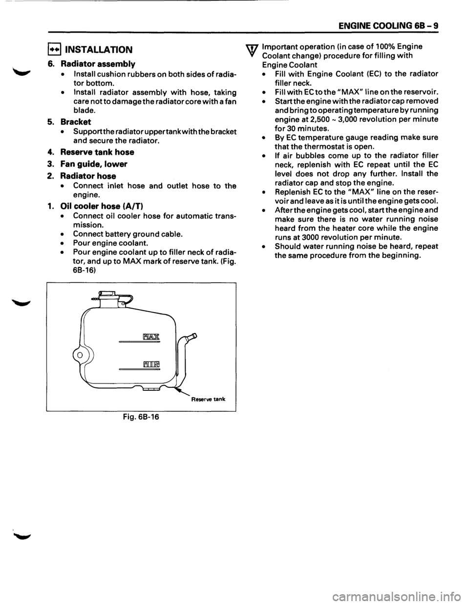
• Pour engine coolant up to filler neck of radia
tor, and up to MAX mark of reserve tank. (Fig.
68-16)
Reserve tank
Fig. 68-16
ENGINE COOLING 68-9
U7 Important operation (in case of 100% Engine
V Coolant change) procedure for filling with
Engine Coolant
• Fill
with Engine Coolant (EC) to the radiator
filler neck.
• Fill with EC to the "MAX" line on the reservoir.
• Start the engine with the radiator cap removed
and bring
to operating temperature by running
engine at
2,500-3,000 revolution per minute
for 30 minutes.
• By EC temperature gauge reading make sure
that the thermostat is open.
• If air bubbles come up to the radiator filler
neck, replenish with EC repeat until the EC
level does not drop any further. Install the
radiator cap and stop the engine.
• Replenish EC to the "MAX" line on the reser
voir and leave as it is until the engine gets cool.
• After the engine gets cool, start the engine and
make sure there is no
water running noise
heard
from the heater core while the engine
runs
at 3000 revolution per minute.
• Should water running noise be heard, repeat
the same procedure from the beginning.
Page 638 of 1928
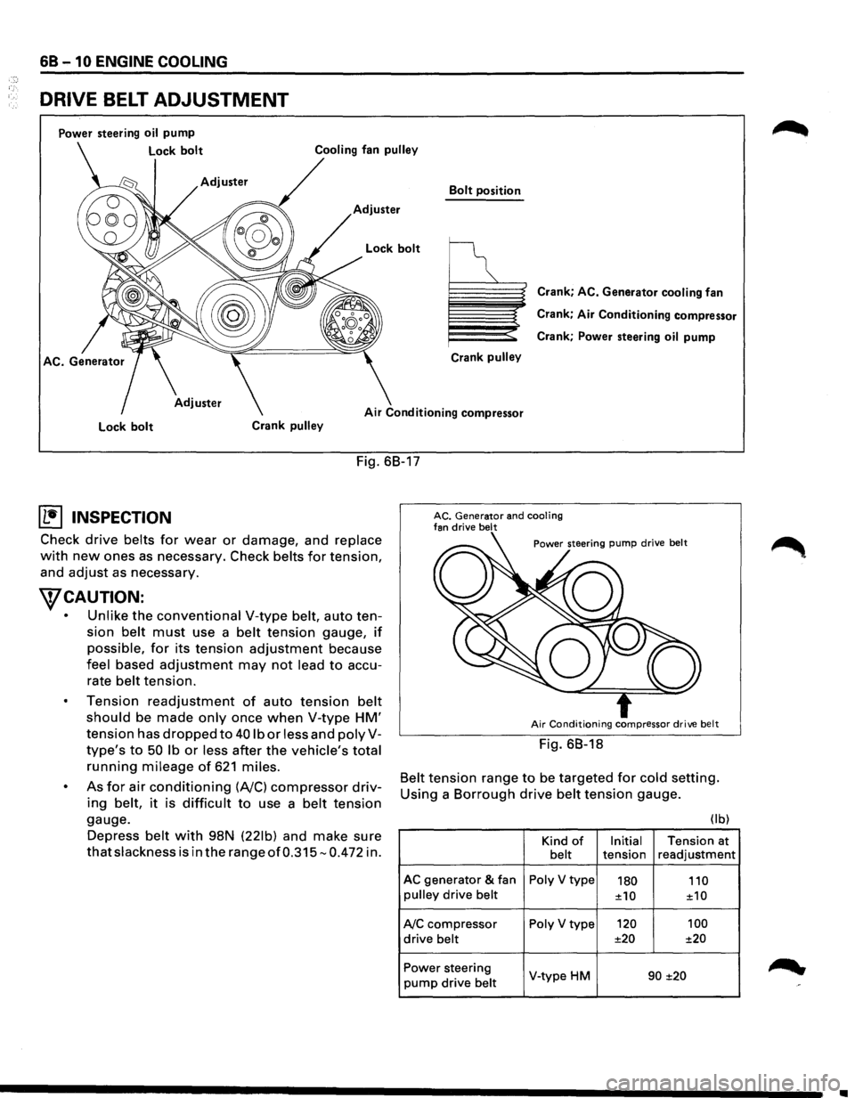
68 -10 ENGINE COOLING
DRIVE BELT ADJUSTMENT
Power steering oil pump
Lock bolt
Bolt position
Adjuster
Crank
pulley
Crank; AC. Generator cooling fan
Crank;
Air Conditioning compressor
Crank; Power steering
oil pump
Air Conditioning compressor
Lock bolt Crank pulley
Fig. 68-17
(b!] INSPECTION
Check drive belts for wear or damage, and replace
with new ones as necessary. Check belts for tension,
and
adjust as necessary.
WCAUTION:
• Unlike the conventional V-type belt, auto ten
sion
belt must use a belt tension gauge, if
possible, for its tension adjustment because
feel based adjustment may not lead to accu
rate
belt tension.
Tension
readjustment of auto tension belt
should be made only once when V-type HM'
tension has dropped to 40 lb or less and polyV
type's to 50 lb or less after the vehicle's total
running mileage of 621 miles.
As for air conditioning (A/C) compressor driv
ing belt, it is difficult to use a belt tension
gauge.
Depress
belt with 98N (221b) and make sure
that slackness is in the range of0.315-0.472 in.
AC. Generator and cooling fan drive belt
Air Conditioning compressor drive belt
Fig. 68-18
Belt tension range to be targeted for cold setting.
Using a
Borrough drive belt tension gauge.
(I b)
Kind of Initial Tension at belt tension readjustment
AC generator & fan Poly V type 180 110 pulley drive belt ±10
±10
A/C compressor Poly V type 120
100
drive belt ±20
±20
Power steering
V-type HM 90 ±20 pump drive belt
•
Page 639 of 1928
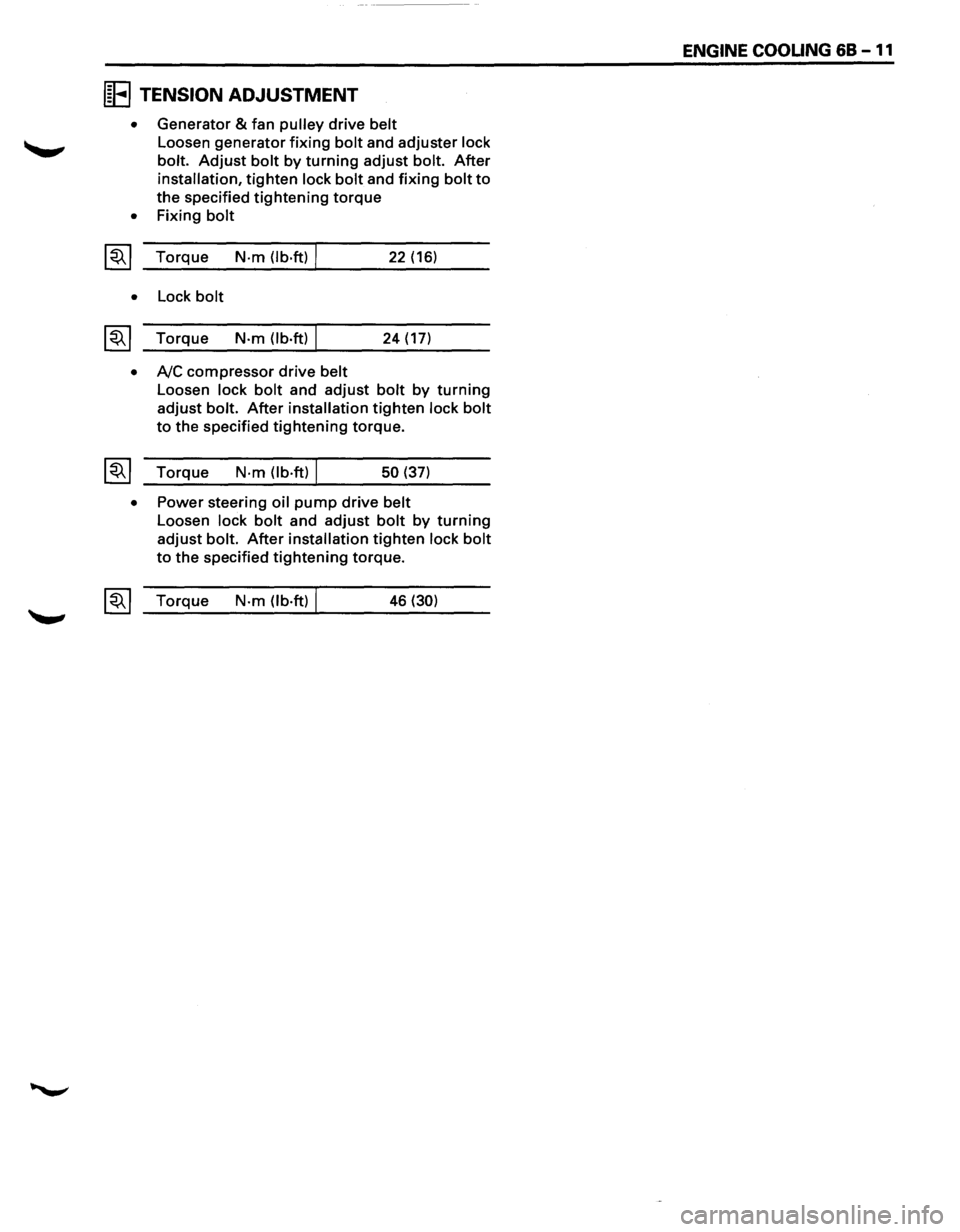
IE TENSION ADJUSTMENT
• Generator & fan pulley drive belt
Loosen generator fixing bolt and adjuster lock
bolt.
Adjust bolt by turning adjust bolt. After
installation, tighten lock bolt and fixing bolt to
the specified tightening torque
• Fixing bolt
~~~ Torque N·m (lb·ft) I 22 (16)
• Lock bolt
~~~ Torque N·m (lb.ft) I 24 (17)
• A/C compressor drive belt
Loosen lock bolt and adjust bolt by turning
adjust bolt. After installation tighten lock bolt
to the specified tightening torque.
~~~ Torque N·m (lb·ft) I 50 (37)
• Power steering oil pump drive belt
Loosen lock bolt and adjust bolt by turning
adjust bolt. After installation tighten lock bolt
to the specified tightening torque.
~~~ Torque N·m (lb·ft) I 46 (30)
ENGINE COOUNG 68 -11
Page 643 of 1928
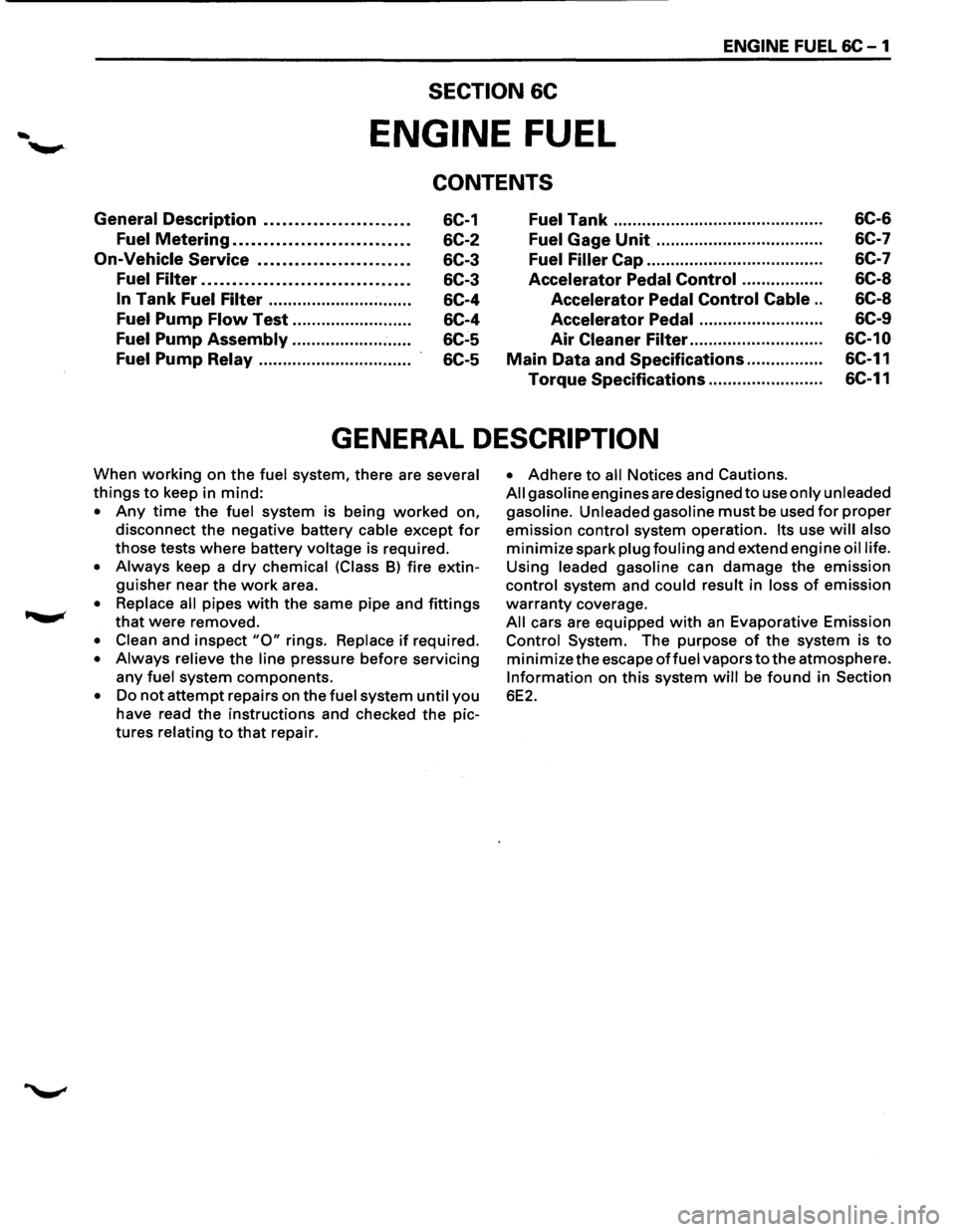
ENGINE FUEL 6C-1
SECTION 6C
ENGINE FUEL
CONTENTS
General Description ....................... .
Fuel Metering ............................ .
On-Vehicle Service ........................ .
Fuel Filter ................................. .
In Tank Fuel Filter ............................. .
Fuel Pump Flow Test ........................ .
Fuel Pump Assembly ........................ .
Fuel Pump Relay .............................. ..
6C-1
6C-2
6C-3
6C-3
6C-4
6C-4
6C-5
6C-5
Fuel Tank .......................................... ..
Fuel Gage Unit ................................. ..
Fuel Filler Cap .................................... .
Accelerator Pedal Control ............... ..
Accelerator Pedal Control Cable ..
Accelerator Pedal ......................... .
Air
Cleaner Filter ........................... .
Main Data and Specifications ............... .
Torque Specifications ......................
..
6C-6
6C-7
6C-7
6C-8
6C-8
6C-9
6C-10
6C-11
6C-11
GENERAL DESCRIPTION
When working on the fuel system, there are several
things to keep in mind:
• Any time the fuel system is being worked on,
disconnect the negative battery
cable except for
those tests where battery voltage is required.
• Always keep a dry chemical (Class 8) fire extin
guisher near the work area.
• Replace all pipes with the same pipe and fittings
that were removed.
• Clean and inspect "0" rings. Replace if required.
• Always relieve the line pressure before servicing
any fuel system components.
• Do not attempt repairs on the fuel system until you
have read the instructions and checked the pic
tures
relating to that repair.
• Adhere to all Notices and Cautions.
All gasoline engines are designed to use only unleaded
gasoline. Unleaded gasoline
must be used for proper
emission control system operation. Its use will also
minimize spark plug fouling and extend engine oil life.
Using leaded gasoline can damage the emission
control system and could result in loss of emission
warranty coverage.
All cars are equipped with an Evaporative Emission
Control System. The purpose of the system is to
minimize the escape offuel vapors to the atmosphere.
Information on this system will be found in Section
6E2.
Page 659 of 1928
CRANKING SYSTEM 6D2 - 1
SECTION 602
CRANKING SYSTEM
CONTENTS
General Description ....................... .
Diagnosis
.................................... .
On-Vehicle Service ........................ . 6D2-1
6D2-3
6D2-8 Unit
Repair.................................... 6D2-9
Main Data and Specifications
............ 6D2-17
Torque Specifications
...................... 6D2-18
GENERAL DESCRIPTION
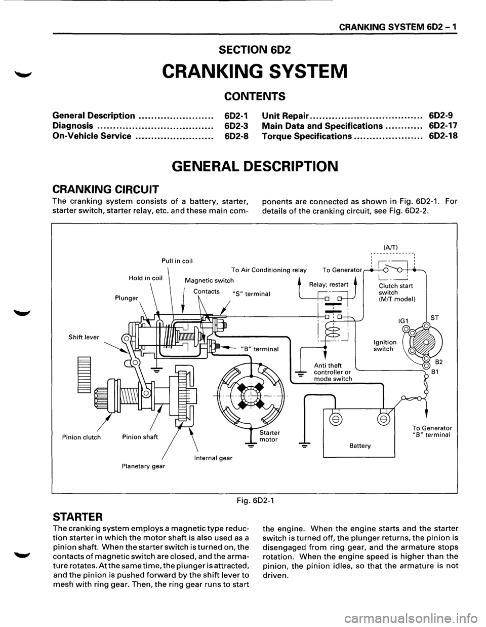
CRANKING CIRCUIT
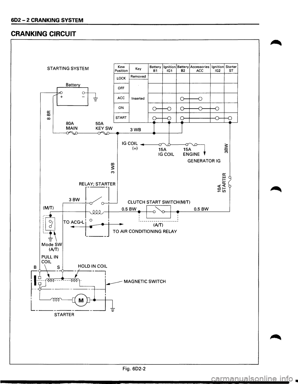
The cranking system consists of a battery, starter,
starter switch, starter relay, etc. and these main com-
Pull in coil
Hold
in coil
Plunger
Shift lever
Pinion clutch
Internal
gear
Planetary gear
ponents are connected as shown in Fig. 602-1. For
details of the cranking circuit, see Fig. 602-2.
Anti theft controller or mode switch
Battery
(AfT} '-------------. ' '
To Generator "B" terminal
Fig. 602-1
STARTER
The cranking system employs a magnetic type reduc
tion starter in which the motor shaft is also used as a
pinion shaft. When the starter switch is turned on, the
contacts of magnetic switch are closed, and the arma
ture rotates. At the same time, the plunger is attracted,
and the pinion is pushed forward by the shift lever to
mesh with ring gear. Then, the ring gear runs to start
the engine. When the engine starts and the starter
switch is turned off, the plunger returns, the pinion is
disengaged from ring gear, and the armature stops
rotation. When the engine speed is higher than the
pinion, the pinion idles, so that the armature is not
driven.
Page 660 of 1928
602 - 2 CRANKING SYSTEM
CRANKING CIRCUIT
STARTING SYSTEM
a: co 00
/ +
Battery
50 A
Kew
Position
LOCK
OFF
Key
Removed
ACC Inserted
ON
START Battery
Ignition Battery
Accessories Ignition Starter B1 IG1 B2 ACC IG2 ST
o----o
o----o
oc l---+----+--<0---o
BOA MAIN KEYSW 3WB I I ~~ ...;~-4:) -
IG COIL --------1~-:r uJ----a~ (+) 15A 15A IG COIL ENGINE
GENERATOR IG co :5: ('f)
RELAY; STARTER
3BW r---~
._,()-.L___j -v CLUTCH START SWITCH(M/T)
0.5
BW-I '~ I -0.5 BW ~-+-4~--~~~------~ T I ~ I T : ___________________ ~
.. (NT)
TO AIR CONDITIONING RELAY
Mode SW (NT)
PULLIN
B C\~L _S -/OLD I~ COl~
fl-~ooe--------O<>Ol -----MAGNETIC SWITCH
~-T ------+-----~.
I M
L _______ _
STARTER
Fig. 602-2
•
Page 661 of 1928
CRANKING SYSTEM 602 -3
DIAGNOSIS
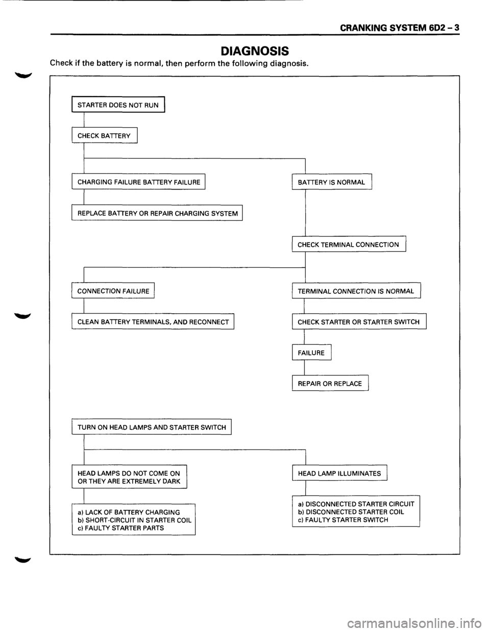
Check if the battery is normal, then perform the following diagnosis.
I STARTER DOES NOT RUN I
I CHECK BATTERY I
I
CHARGING FAILURE BATTERY FAILURE I I BATTERY IS NORMAL I
I REPLACE BATTERY OR REPAIR CHARGING SYSTEM I
I
CHECK TERMINAL CONNECTION
I CONNECTION FAILURE I I TERMINAL CONNECTION IS NORMAL J
I CLEAN BATTERY TERMINALS, AND RECONNECT I
I CHECK STARTER OR STARTER SWITCH I
I FAILURE I
I REPAIR OR REPLACE I
TURN ON HEAD LAMPS AND STARTER SWITCH I
I
HEAD LAMPS DO NOT COME ON HEAD LAMP ILLUMINATES I OR THEY ARE EXTREMELY DARK
I
a) DISCONNECTED STARTER CIRCUIT
a) LACK OF BATTERY CHARGING b) DISCONNECTED STARTER COIL
b) SHORT-CIRCUIT IN STARTER COIL c) FAULTY STARTER SWITCH
c) FAULTY STARTER PARTS