ABS ISUZU TROOPER 1995 Workshop Manual
[x] Cancel search | Manufacturer: ISUZU, Model Year: 1995, Model line: TROOPER, Model: ISUZU TROOPER 1995Pages: 1928
Page 1239 of 1928
!! (Q
(
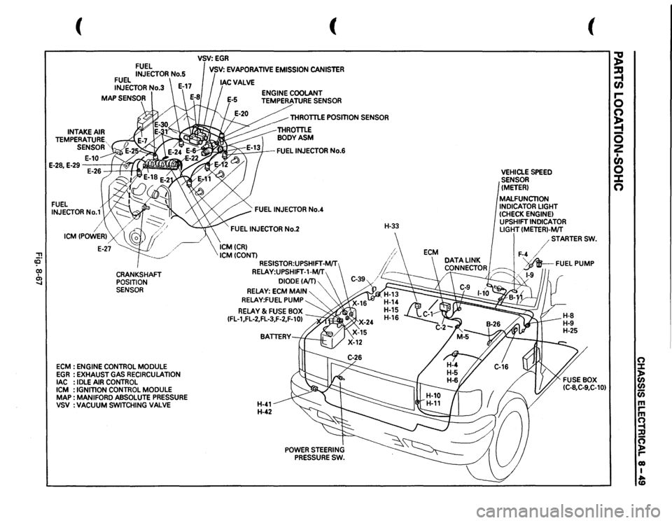
FUEL INJECTOR
No.1
/
FUEL INJECTOR
No.5
FUEL INJECTOR
No.3
I
\/.
ICM
CPOWERl
_/
E-27
cp
I
CRANKSHAFT
~
POSITION SENSOR
ECM
: ENGINE
CONTROL
MODULE
EGR
:EXHAUST
GAS
RECIRCULATION
lAC
: IDLE
AIR
CONTROL
ICM
: IGNmON
CONTROL
MODULE
MAP
: MAN
I FORD
ABSOLUTE
PRESSURE
VSV
:VACUUM
SWITCHING
VALVE
(
VSV:EGR I VSV:
EVAPORATIVE
EMISSION
CANISTER
THROTTLE
POSmON
SENSOR
~FUEL
INJECTOR
No.6
FUEL
INJECTOR
No.4
FUEL
INJECTOR
No.2
ICMCCRl ICMCCONTl
RESISTOR:UPSHIFT-MIT RELAY:UPSHIFT-1-MIT
DIODECAITl
RELAY:
ECM
MAIN
RELAY:FUEL
PUMP
RELAY
& FUSE
BOX
CFL-1,FL-2,FL-3,F-2,F-10l
H-41 H-42
POWER
STEERING
PRESSURE
SW.
H-33
VEHICLE
SPEED
SENSOR (METER) MALFUNCTION INDICATOR
LIGHT
(CHECK
ENGINE)
UPSHIFT
INDICATOR
LIGHT
CMETERl-MfT
(
/STARTER
SW.
F-4
/
DATA
LINK
I
d .
'v_AR__
FUEL
PUMP
CONNECTOR~
!P
~;~·
/~
,,
1-9
~ ~ r-0 n ~ 0 2 • en 0 X n
(") ::::1: )> CJ)
CJ) Cii m rm ~ :D ~ r-01) I fD
Page 1251 of 1928
CHASSIS ELECTRICAL 8-61
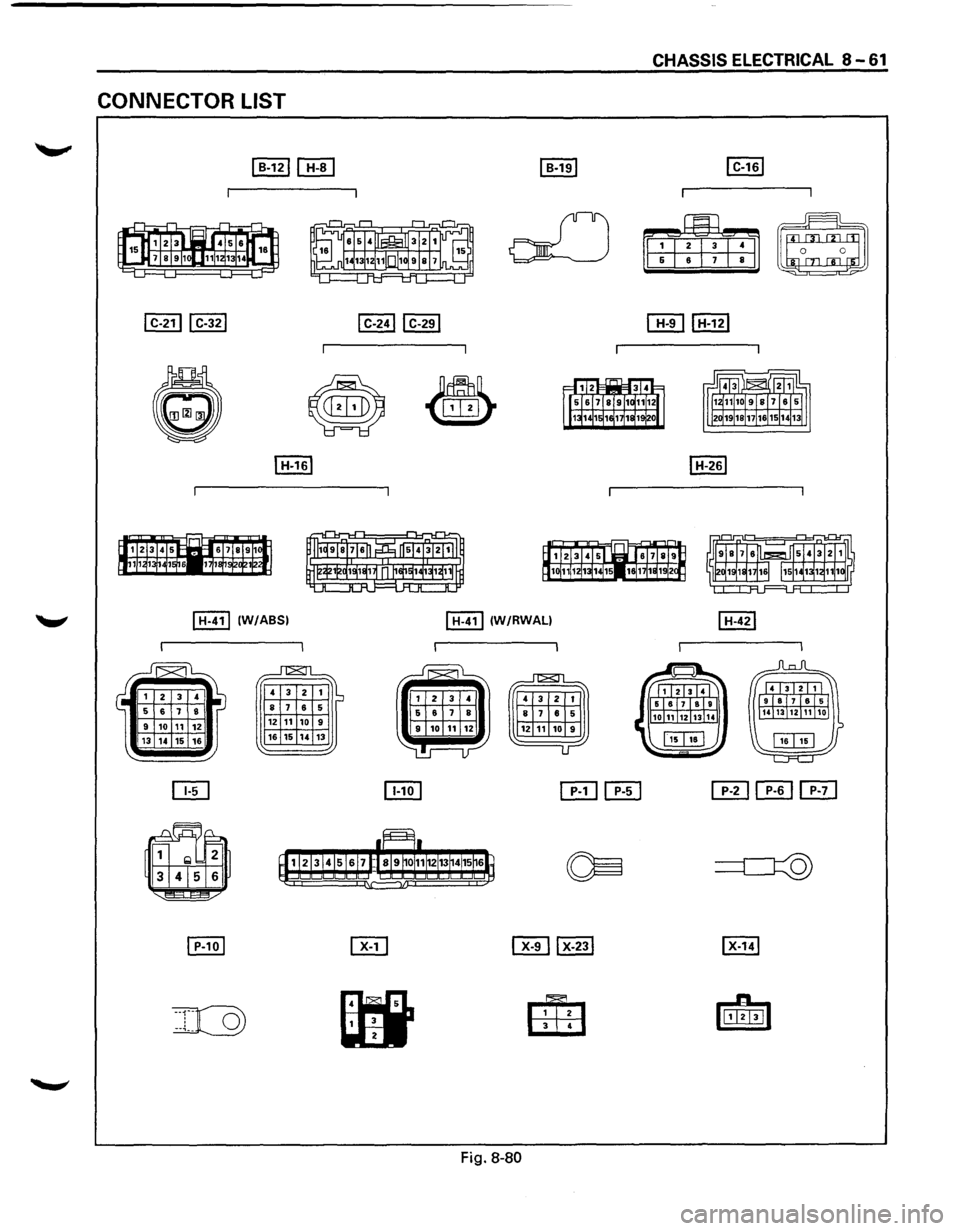
CONNECTOR LIST
I H-41l (W/ABSI I H-41l (W/RWALI
~
4 3
2 1 ~ 8 7 6 5
12 11 10 9
16 15 14 13
Fig. 8-80
Page 1270 of 1928
8 -80 CHASSIS ELECTRICAL
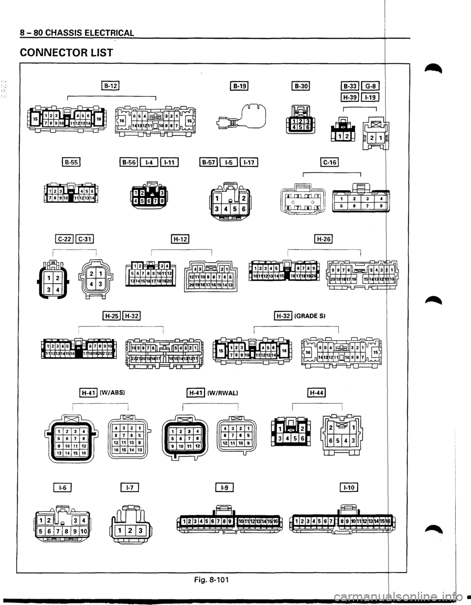
CONNECTOR LIST
I H-411 (W/ABSI
...Jl2SJl
4 3
2 1
8 7 6 5
12 11 10 9 16 15 14 13
~
~
~
I H-411 IW/RWALI
Fig. 8-101
I H-321 (GRADE 51
•
Page 1299 of 1928
![ISUZU TROOPER 1995 Workshop Manual CONNECTOR LIST
~
~
I B-531
•
I C-431
I C-161
I H-321 !GRADE S)
I H-411 IW/RWALI
CHASSIS ELECTRICAL 8 - 1 09
I C-2211 C-311 I C-2711 C-281
~J 1 c 0 J
G) 4
•
I
[[Til H-121
~
~
Fig.](/img/61/57183/w960_57183-1298.png "ISUZU TROOPER 1995 Workshop Manual CONNECTOR LIST
~
~
I B-531
•
I C-431
I C-161
I H-321 !GRADE S)
I H-411 IW/RWALI
CHASSIS ELECTRICAL 8 - 1 09
I C-2211 C-311 I C-2711 C-281
~J 1 c 0 J
G) 4
•
I
[[Til H-121
~
~
Fig.")
CONNECTOR LIST
~
~
I B-531
•
I C-431
I C-161
I H-321 !GRADE S)
I H-411 IW/RWALI
CHASSIS ELECTRICAL 8 - 1 09
I C-2211 C-311 I C-2711 C-281
~J 1 c 0 J
G) 4
•
I
[[Til H-121
~
~
Fig. 8-138
I H-101
~
4 3 2 1 IS 8 7 6 5
12 11 10 9
18 15 14 13
I H-411 (W/ABS)
~
4 3 2 1 ~ 8 7 6 5
12 11 10 9
16 15 14 13
Page 1368 of 1928
8 -178 CHASSIS ELECTRICAL
ANTI-LOCK BRAKE SYSTEM (ABS)
GENERAL DESCRIPTION
The circuit consists of the starter switch, stoplight switch (vehicle w/o cruise control), brake switch (vehicle
with cruise control), hydraulic unit, electronic brake control module, wheel speed sensor, G sensor, ABS and
4WD indicator, 4WD switch and data link connector.
When the service brake is applied while in the running mode,
the EBCM (Electronic Brake Control Module)
judges
which wheel is about to lock by using the wheel rotation speed signals sent from the four ABS speed
sensors at the
front and rear wheels. And the brake fluid pressure applied to the four wheels is controlled by
a hydraulic unit to prevent the wheels from locking.
Based on the wheel rotation speed signals
input from the ABS sensor, the EBCM sends out signals to the
solenoid valve in the hydraulic unit
to increase, maintain or decrease the brake fluid pressure. The solenoid
valve uses this signal
to control the fluid pressure which is applied to the calipers of the disk brakes of the
front wheels. (The system also controls at the same time the fluid pressure applied to the rear wheels.)
• EBCM (Electronic brake control module)
The EBCM uses the signals sent from the speed sensor to control the operation of the hydraulic unit.
When any malfunction occurs in the ABS, the
EBCM activates the fail-safe fuction while turning on the
ABS warning light.
• Hydraulic unit
The hydraulic unit consists of the motor, plunger pump, solenoid valve, and fluid pressure control
valves. The exterior
of the unit has a relay box consisting of the motor relay and valve relay. Three
solenoid valves, the
two of which are provided at the front wheels and the one at the rear wheels, control
the fluid pressure
of these wheels.
• Speed sensor
The speed sensor consists of the sensor and the rotor. It sends the EBCM the AC voltage generated by
the rotation of the rotor as the vehicle speed signal. ~
• G-sensor
The G-sensor, installed inside the center console, sends out signals to the EBCM by detecting the
decelerating speed
of the vehicle.
• ABS warning light
The ABS warning light in the instrument panel, lights up when any malfunction occurs in the ABS. It also
lights up
with the starter key at the "ON" position, as a self-check.
Refer
to Section 5A4, "ANTI-LOCK BRAKE SYSTEM" for detail.
II
Page 1369 of 1928
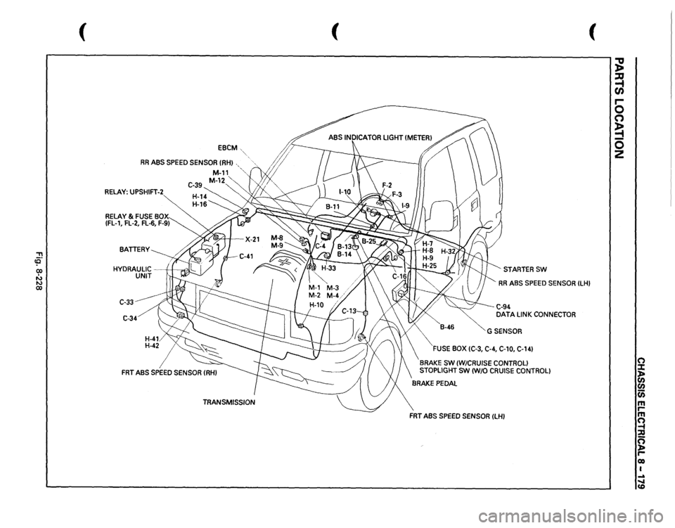
::!! (Q 00 I N N 00
(
EBCM
RR
ABS
SPEED
SENSOR
(RHI
RELAY:
UPSHIFT-2
C-33 C-34
(
(
STARTERSW RR
ABS
SPEED
SENSOR
ILHI
C-94 DATA
LINK
CONNECTOR
GSENSOR
FUSE
BOX
(C-3,
C-4,
C-10,
C-141
BRAKE
SW
(W/CRUISE
CONTROL)
STOPLIGHT
SW
IW/0
CRUISE
CONTROL)
FRT
ABS
SPEED
SENSOR
ILHI
~ :a -t CJ) r-0 (") ~ 0 z
(") :::t ln en (i) m rm ~ :;g n ~ r-eo I ..a ..... CD
Page 1378 of 1928
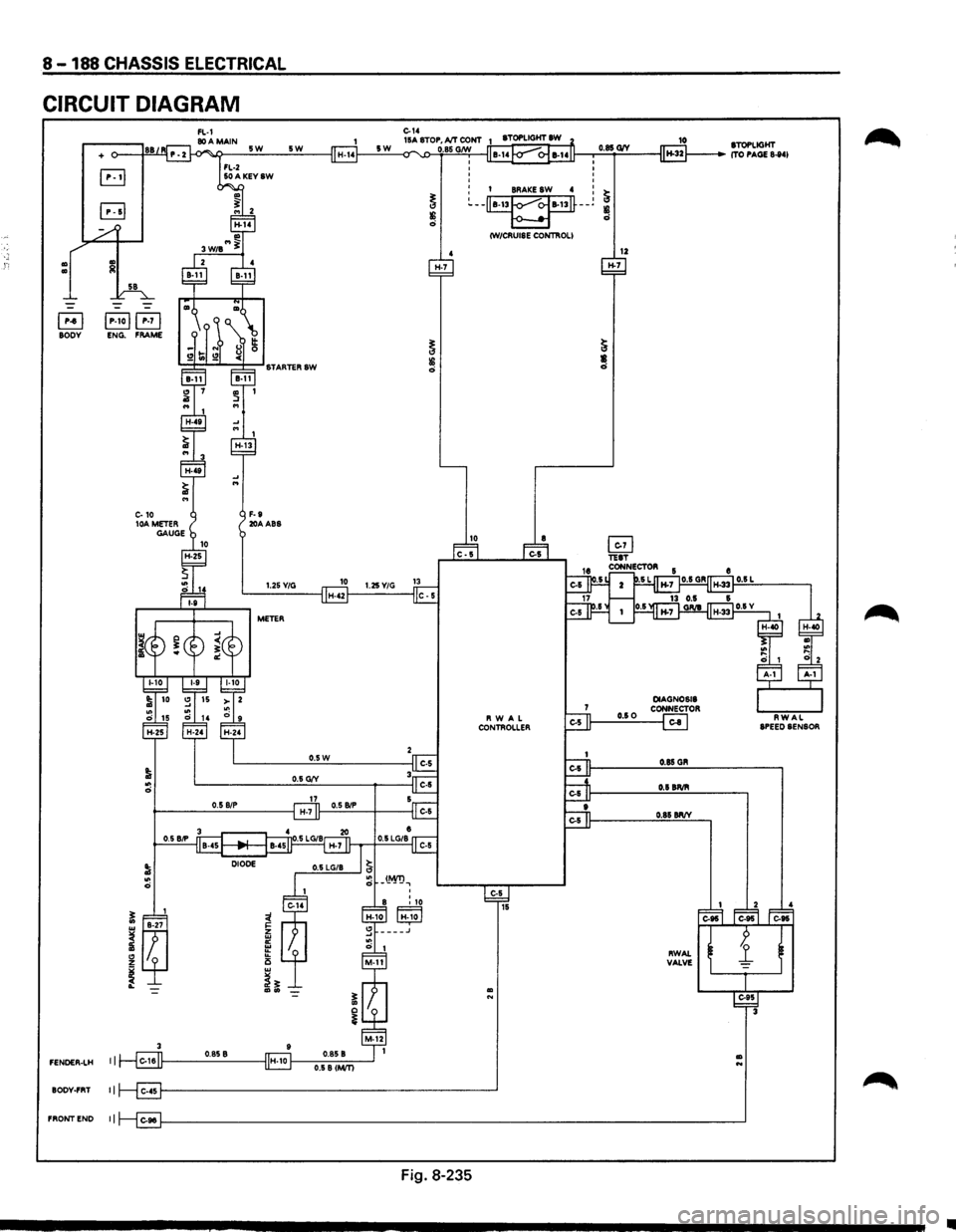
8-188 CHASSIS ELECTRICAL
CIRCUIT DIAGRAM
Ill Ill
+
B jP-toj~ BODY ENG. FRAME
3
FENOER-LH I I
BODY-FRT II
FRONTEND II
5W
F-9 20AABS
5W
1.25Y/G
METER
H-7
0
0 0
0
0.85 G1V
o I BRAKE SW 4 : ~ ~--~--~
~ ~ CW/CRUISE CONTROLI
12 H-7
Fig. 8-235
10 STOPLIGHT ITO PAGE 8-841
•
Page 1425 of 1928
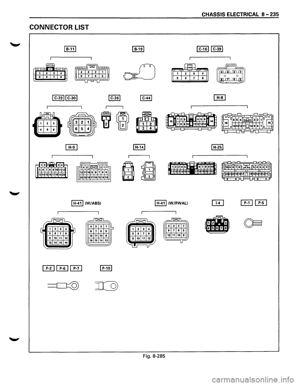
CONNECTOR LIST
~
~
I H-411 (W/ABSI
~
4 3 2
8 7 6 1 5 12 11 10 9 16 15
14 13
I H-411 (W/RWALI
b
Fig. 8-285
CHASSIS ELECTRICAL 8 -235
~
~
Page 1483 of 1928
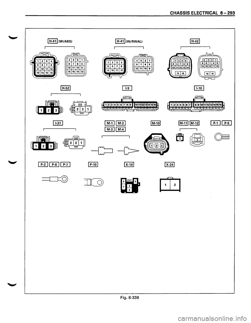
CHASSIS ELECTRICAL 8 -293
I H-411 (W/ABSI I H-41 l!wtRWALI
~ J"T&Tl
' 3 2 1 ~~ 8 7 • 5 ' 3 2 1
8 7 • 5 12 11 10 9 12 11 10 9
16 15 14 13 1J
ITIHTIJ
Fig. 8-339
Page 1507 of 1928
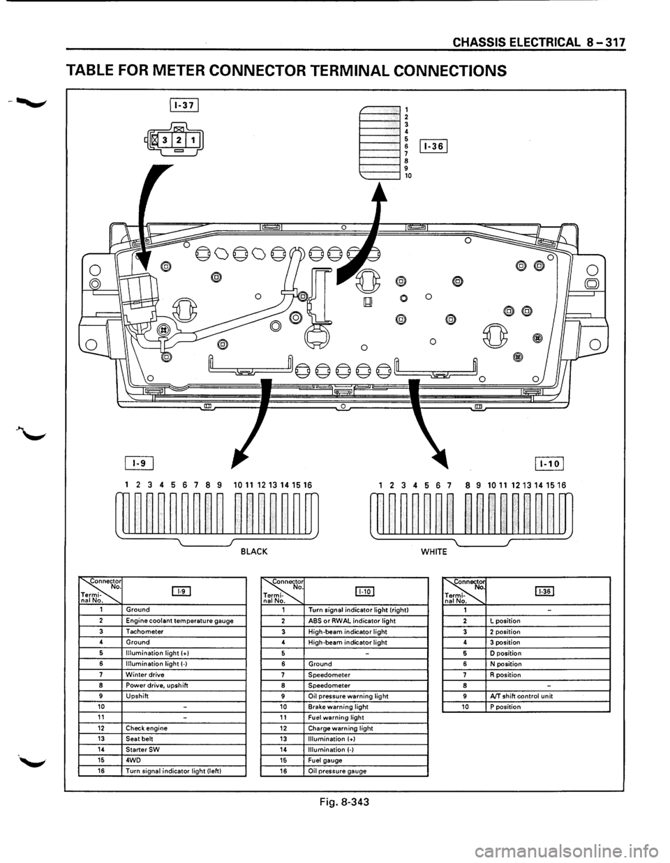
CHASSIS ELECTRICAL 8-317
TABLE FOR METER CONNECTOR TERMINAL CONNECTIONS
~-""""""', 1----""'12 1----""'1! 6 1----l 6 [Iill
1----""'1 ~ 9 1---""'l,o
®
0 0
0
® @
0 0 ~
~m© © © © ©'--m ~~0
0 !III
1 2 3 4 5 6 7 8 9 1011 1213141516 1 2 3 4 56 7 8 9 10111213141516
w~~~~~~~~ ~~~~~~m rn~~~~~~ ~~nn~~m
~ I J BLACK WHITE
~r o. DTI -na No. ~
. IJJ:Q] -
. ~ [ill] . -. 1 Ground 1 Turn
signal indicator light (right)
1 -2 Engine coolant temperature gauge 2 ABS or RWAL indicator light 2 L
position
3 Tachometer 3 High-beam indicator light 3 2 position 4
Ground
4 High-beam
indicator light 4 3 position 6 Illumination light (+I 5 -5 D position
6 Illumination light(-) 6 Ground 6 N position 7 Winter drive 7 Speedometer 7 R position 8 Power drive, upshift 8 Speedometer 8 -9 Upshift 9 Oil pressure warning light 9 AfT shift control unit 10 -10 Brake warning light 10 P position 11 -11 Fuel warning light 12 Check engine 12 Charge warning light 13 Seat belt 13 Illumination (+) 14 StarterSW 14 Illumination (-) 15 4WD 15 Fuel gauge 16 Turn signal indicator light (left) 16 Oil pressure gauge
Fig. 8-343