belt ISUZU TROOPER 1995 Owner's Manual
[x] Cancel search | Manufacturer: ISUZU, Model Year: 1995, Model line: TROOPER, Model: ISUZU TROOPER 1995Pages: 1928
Page 579 of 1928
I••IINSTALLATION
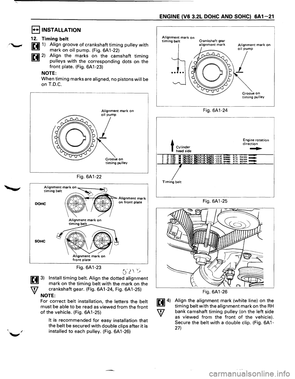
12. Timing belt
1£4111) Align groove of crankshaft timing pulley with
mark on oil pump. (Fig. 6A 1-22)
1£4112) Align the marks on the camshaft timing
pulleys with the corresponding dots on the
front plate. (Fig. 6A 1-23)
NOTE:
When timing marks are aligned, no pistons will be
on T.D.C.
,-----------------------------,
Fig. 6A1-22
Groove on timing pulley
Alignment mark on~ ad]
timing belt ·~Alignment mark
DOHC ", ' on front plate Q',
SOHC
Fig. 6A1-23 '"-) ,.· (.)~\,'j
1£4113) Install timing belt. Align the dotted alignment
mark on the timing belt with the mark on the
W crankshaft gear. (Fig. 6A1-24, Fig. 6A1-25)
NOTE:
For correct belt installation, the letters the belt
must be able to be read as viewed from the front
of the vehicle. (Fig. 6A 1-25)
It is recommended for easy installation that
the belt be secured with double clips after it is
installed to each pulley. (Fig. 6A 1-26)
ENGINE (V6 3.2L DOHC AND SOHC) 6A1-21
Alignment mark on timing belt Crankshaft gear alignment mark
L~---
t Cylinder head side
Timing belt
Fig. 6A1-24
Fig. 6A1-25
Fig. 6A1-26
Engine rotation direction
~
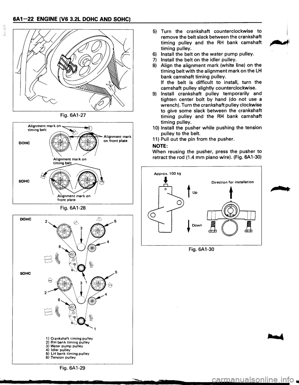
Align the alignment mark (white line) on the
timing belt with the alignment mark on the RH
bank camshaft timing pulley (on the left side
as viewed from the front of the vehicle).
Secure
the belt with a double clip. (Fig. 6A 1-
27)
Page 580 of 1928
&A 1-22 ENGINE (V& 3.2L DOHC AND SOHC)
Fig. 6A1-27
Alignment mark on ~ timing belt ~
DOHC " ' on front plate
~~
Alignment mark
_","'
SOHC
DOHC
SOHC
/ Alignment mark on timing belt
Fig. 6A1-28
1) Crankshaft timing pulley 2) RH bank timing pulley 3) Water pump pulley 4) Idler pulley 5) LH bank timing pulley 6) Tension pulley
fig. 6A1-29
5) Turn the crankshaft counterclockwise to
remove the belt slack between the crankshaft
timing
pulley and the RH bank camshaft ,.......,,
timing pulley.
6) Install the belt on the water pump pulley.
7) Install the belt on the idler pulley.
8) Align the alignment mark (white line) on the
timing belt with the alignment mark on the
LH
bank camshaft timing pulley.
If
the belt is difficult to install, turn the
camshaft
pulley slightly counterclockwise.
9) Install crankshaft pulley temporarily and
tighten center bolt by hand (do
not use a
wrench). Turn the crankshaft
pulley clockwise
to give some slack between the crankshaft
timing
pulley and the RH bank camshaft
timing
pulley.
1 0) Install the pusher while pushing the tension
pulley to the belt.
11) Pull out the pin from the pusher.
NOTE:
When reusing the pusher, press the pusher to
retract the rod (1.4 mm piano wire). (Fig. 6A 1-30)
Approx. 100 kg
... Direction for installation
Fig. 6A1-30
,.. ..
•
Page 581 of 1928
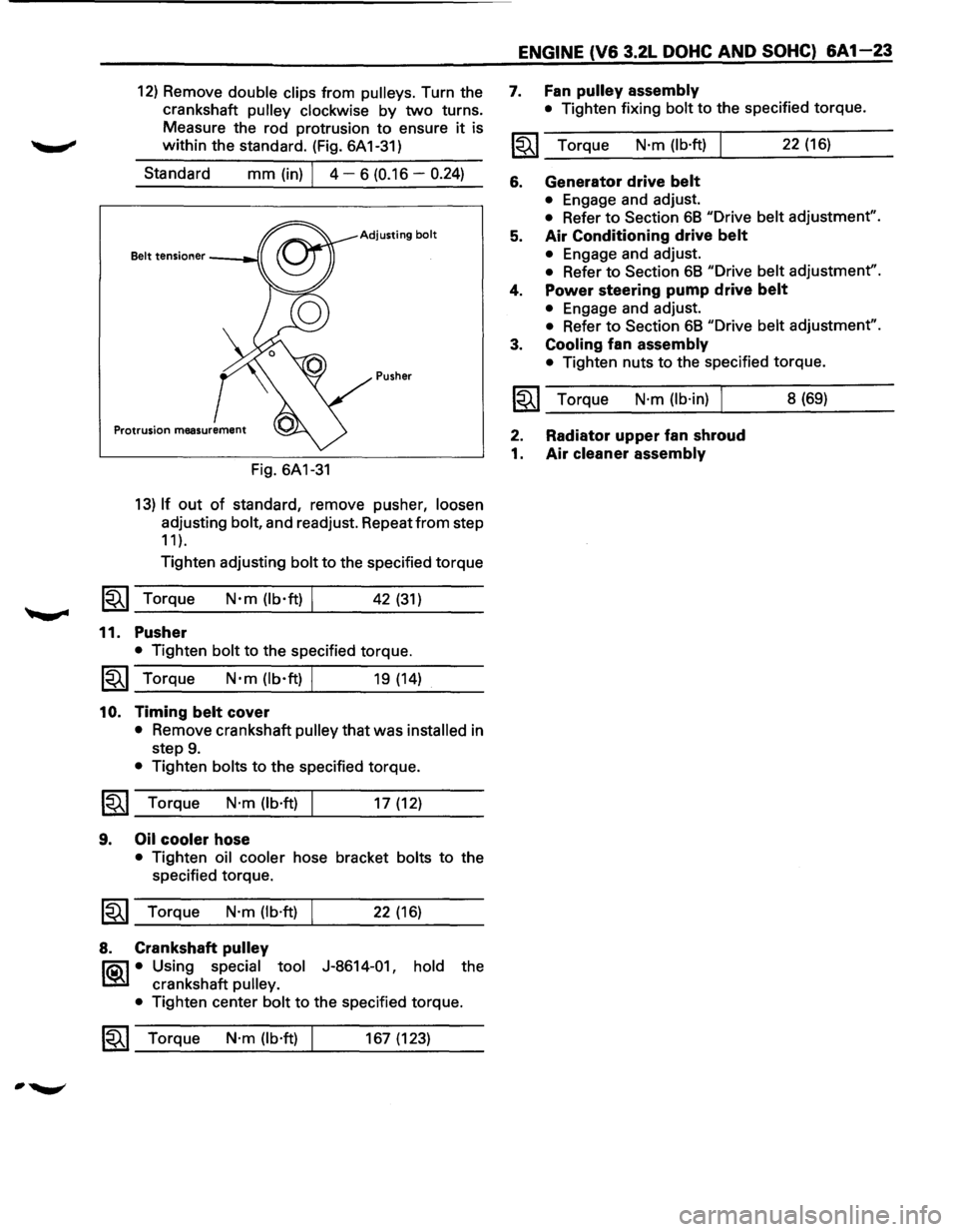
12) Remove double clips from pulleys. Turn the
crankshaft
pulley clockwise by two turns.
Measure the rod protrusion to ensure
it is
within the standard. (Fig. 6A 1-31)
Standard
mm (in) I 4 - 6 (0.16 -0.24)
Adjusting bolt
Pusher
Fig. 6A1-31
13) If out of standard, remove pusher, loosen
adjusting bolt, and readjust. Repeat from step
11 ).
Tighten adjusting bolt to the specified torque
1~1 Torque N·m (lb·ft) I 42 (31)
11. Pusher
• Tighten bolt to the specified torque.
1~1 Torque N·m (lb·ft) I 19 (14)
10. Timing belt cover
• Remove crankshaft pulley that was installed in
step
9.
• Tighten bolts to the specified torque.
~~~ Torque N·m (lb·ft) I 17 (12)
9. Oil cooler hose
• Tighten oil cooler hose bracket bolts to the
specified torque.
~~~ Torque N·m (lb·ft) I 22 (16)
8. Crankshaft pulley
l"iQ\1 • Using special tool J-8614-01, hold the
~ crankshaft pulley.
•
Tighten center bolt to the specified torque.
1~1 Torque N·m (lb·ft) 167 (123)
ENGINE (V6 3.2L DOHC AND SOHC) 6A1-23
7. Fan pulley assembly
• Tighten fixing bolt to the specified torque.
~~~ Torque N·m (lb·ft) 22 (16)
6. Generator drive belt
• Engage and adjust.
• Refer to Section 68 "Drive belt adjustment".
5. Air Conditioning drive belt
• Engage and adjust.
• Refer to Section 68 "Drive belt adjustment".
4. Power steering pump drive belt
• Engage and adjust.
• Refer to Section 68 "Drive belt adjustment".
3. Cooling fan assembly
• Tighten nuts to the specified torque.
~~~ Torque N·m (lb·in) I 8 (69)
2. Radiator upper fan shroud
1. Air cleaner assembly
Page 582 of 1928
, r;
6A 1-24 ENGINE (V6 3.2L DOHC AND SOHC)
CRANKSHAFT PULLEY
1 2
7 4
6
3
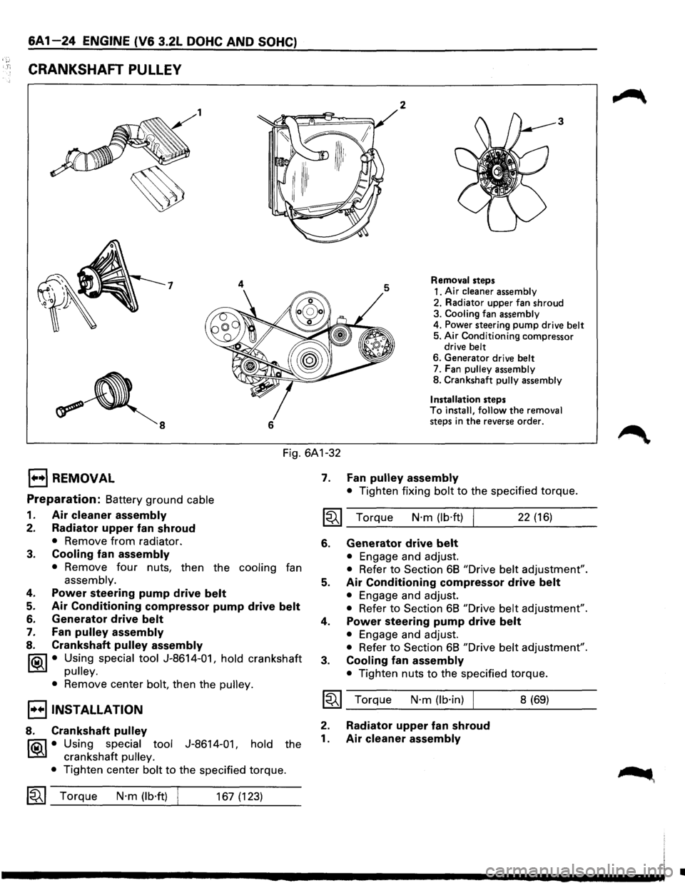
Removal steps
1. Air
cleaner assembly
2. Radiator upper fan shroud
3. Cooling fan assembly
4. Power steering pump drive belt 5. Air Conditioning compressor
drive belt
6. Generator drive belt 7. Fan pulley assembly
8. Crankshaft pully assembly
Installation
steps To install, follow the removal steps in the reverse order.
Fig. 6A1-32
E) REMOVAL
Preparation: Battery ground cable
1. Air cleaner assembly
2. Radiator upper fan shroud
• Remove from radiator.
3. Cooling fan assembly
• Remove four nuts, then the cooling fan
assembly.
4. Power steering pump drive belt
5. Air Conditioning compressor pump drive belt
6. Generator drive belt
7. Fan pulley assembly
8. Crankshaft pulley assembly
IQil • Using special tool J-8614-01, hold crankshaft
I.:Sil pulley.
•
Remove center bolt, then the pulley.
I••IINSTALLATION
8. Crankshaft pulley
IQil • Using special tool J-8614-01, hold the
I.:Sil crankshaft pulley.
•
Tighten center bolt to the specified torque.
1~1 Torque N·m (lb·ft) 167 (123)
7. Fan pulley assembly
• Tighten fixing bolt to the specified torque.
1~1 Torque N·m (lb·ft) 22 (16)
6. Generator drive belt
• Engage and adjust.
• Refer to Section 68 "Drive belt adjustment".
5. Air Conditioning compressor drive belt
• Engage and adjust.
• Refer to Section 68 "Drive belt adjustment".
4. Power steering pump drive belt
• Engage and adjust.
• Refer to Section 68 "Drive belt adjustment".
3. Cooling fan assembly
• Tighten nuts to the specified torque.
~~~ Torque N·m (lb·in) I
2. Radiator upper fan shroud
1. Air cleaner assembly
8 (69)
•
Page 584 of 1928
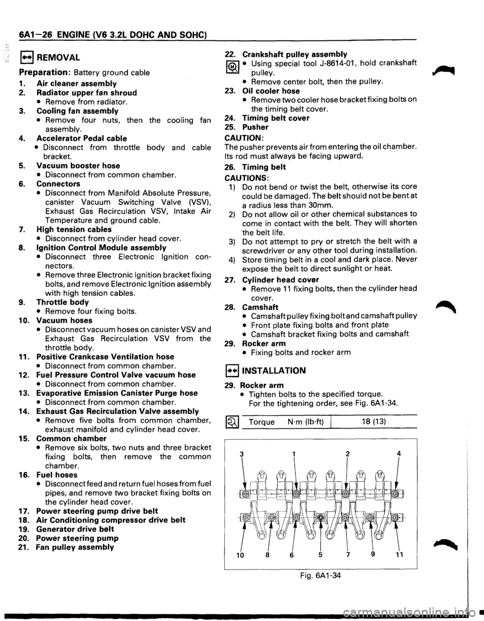
6A1-26 ENGINE (V& 3.2L DOHC AND SOHC)
1••1 REMOVAL
Preparation: Battery ground cable
1. Air cleaner assembly
2. Radiator upper fan shroud
• Remove from radiator.
3. Cooling fan assembly
• Remove four nuts, then the cooling fan
assembly.
4. Accelerator Pedal cable
• Disconnect from throttle body and cable
bracket.
5. Vacuum booster hose
• Disconnect from common chamber.
6. Connectors
• Disconnect from Manifold Absolute Pressure,
canister Vacuum Switching Valve (VSV),
Exhaust
Gas Recirculation VSV, Intake Air
Temperature and ground cable.
7. High tension cables
• Disconnect from cylinder head cover.
8. Ignition Control Module assembly
• Disconnect three Electronic Ignition con
nectors.
• Remove three Electronic Ignition bracket fixing
bolts, and remove Electronic
Ignition assembly
with high tension cables.
9. Throttle body
• Remove four fixing bolts.
10. Vacuum hoses
• Disconnect vacuum hoses on canister VSV and
Exhaust Gas Recirculation
VSV from the
throttle body.
11. Positive Crankcase Ventilation hose
• Disconnect from common chamber.
12. Fuel Pressure Control Valve vacuum hose
• Disconnect from common chamber.
13. Evaporative Emission Canister Purge hose
• Disconnect from common chamber.
14. Exhaust Gas Recirculation Valve assembly
• Remove five bolts from common chamber,
exhaust manifold and cylinder head cover.
15. Common chamber
• Remove six bolts, two nuts and three bracket
fixing bolts, then remove the
common
chamber.
16. Fuelhoses
• Disconnect feed and return fuel hoses from fuel
pipes, and remove
two bracket fixing bolts on
the cylinder head cover.
17. Power steering pump drive belt
18. Air Conditioning compressor drive belt
19. Generator drive belt
20. Power steering pump
21. Fan pulley assembly
22. Crankshaft pulley assembly
lf5\l • Using special tool J-8614-01, hold crankshaft
t:::!il pulley.
•
Remove center bolt, then the pulley.
23. Oil cooler hose
• Remove two cooler hose bracket fixing bolts on
the timing belt cover.
24. Timing belt cover
25. Pusher
CAUTION:
The pusher prevents air from entering the oil chamber.
Its rod must always be facing upward.
26. Timing belt
CAUTIONS:
1) Do not bend or twist the belt, otherwise its core
could
be damaged. The belt should not be bent at
a radius less than 30mm.
2) Do not allow oil or other chemical substances to
come in contact with the belt. They will shorten
the belt life.
3) Do not attempt to pry or stretch the belt with a
screwdriver
or any other tool during installation.
4) Store timing belt in a cool and dark place. Never
expose the belt
to direct sunlight or heat.
27. Cylinder head cover
• Remove 11 fixing bolts, then the cylinder head
cover.
28. Camshaft
• Camshaft pulley fixing bolt and camshaft pulley
•
Front plate fixing bolts and front plate
• Camshaft bracket fixing bolts and camshaft
29. Rocker arm
• Fixing bolts and rocker arm
I••! INSTALLATION
29. Rocker arm
• Tighten bolts to the specified torque.
For the tightening order, see Fig. 6A 1-34.
~~~ Torque N·m (lb·ft) 18 (13)
Fig. 6A1-34
•
Page 585 of 1928
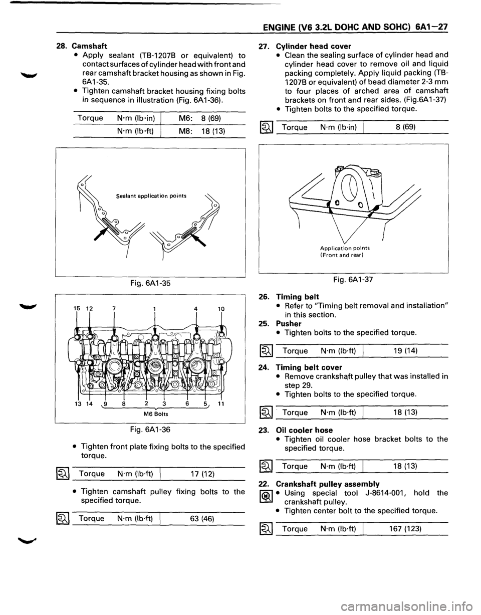
28. Camshaft
• Apply sealant (T8-12078 or equivalent) to
contact surfaces of cylinder head with front and
rear camshaft bracket housing as shown in Fig.
6A1-35.
• Tighten camshaft bracket housing fixing bolts
in sequence in illustration (Fig. 6A1-36).
Torque
N·m (lb·in) M6: 8 (69)
N·m (lb·ft) M8: 18 (13)
Sealant application points
Fig. 6A1-35
15 12 7 4 10
13 14 -...;9;..______:a ___ 2--.....-3 ___ s:-..-.:Js 11
M6 Bolts
Fig. 6A1-36
• Tighten front plate fixing bolts to the specified
torque.
~~~ Torque N·m (lb·ft) 17 (12)
• Tighten camshaft pulley fixing bolts to the
specified torque.
~~~ Torque N·m (lb·ft) ___ _____._ ___ _ 63 (46)
ENGINE (V6 3.2L DOHC AND SOHC) 6A1-27
27. Cylinder head cover
• Clean the sealing surface of cylinder head and
cylinder head cover to remove oil and liquid
packing completely. Apply liquid packing (T8-
12078 or equivalent) of bead diameter 2-3 mm
to four places of arched area of camshaft
brackets on front and rear sides. (Fig.6A 1-37)
• Tighten bolts to the specified torque.
~~~ Torque N·m (lb·in)
26. Timing belt
Application points (Front and rear)
Fig. 6A1-37 8
(69)
• Refer to "Timing
belt removal and installation"
in this section.
25. Pusher
• Tighten bolts to the specified torque.
~~~ Torque N·m (lb·ft) I 19 (14)
24. Timing belt cover
• Remove cranksha.ft pulley that was installed in
step 29.
• Tighten bolts to the specified torque.
~~~ · Torque N·m (lb·ft) I 18 (13)
23. Oil cooler hose
• Tighten oil cooler hose bracket bolts to the
specified torque.
1~1 Torque N·m (lb·ft) 18 (13)
22. Crankshaft pulley assembly
lia\1 • Using special tool J-8614-001, hold the
I.::S::il crankshaft pulley.
•
Tighten center bolt to the specified torque.
~~~ Torque N·m (lb·ft) 167 (123)
Page 586 of 1928
If! (;
6A 1-28 ENGINE (V6 3.2L DOHC AND SOHC)
21. Fan pulley assembly
• Tighten fixing bolt to the specified torque.
~ Torque N·m (lb·ft) I 22 (16)
20.
Power steering pump
• Tighten pump fixing bolts to the specified
torque.
~ Torque N·m (lb·ft) 56 (41)
19. Generator drive belt
• Engage and adjust.
• Refer to Section 68 "Drive belt adjustment".
18. Air Conditioning compressor drive belt
• Engage and adjust.
• Refer to Section 68 "Drive belt adjustment".
17. Power steering pump drive belt
• Engage and adjust.
• Refer to Section 68 "Drive belt adjustment".
16. Fuelhoses
• Connect surely the hoses and install the bolts
on the head cover.
15. Common chamber
• Tighten bolts and nuts to the specified torque.
Bolts
~~~ Torque N·m (lb·ft) 24 (17)
Nuts
~~~ Torque N·m (lb·ft) 24 (17)
14. Exhaust Gas Recirculation Valve assembly
• Tighten bolts to the specified torque.
Exhaust Gas
Recirculation Valve Side
~~~ Torque N·m (lb·in) I 8 (69)
Exhaust Manifold Side
~~~ Torque N·m (lb·ft) 28 (21)
13. Evaporative Emission Canister Purge hose
12.
Fuel Pressure Control Valve vacuum hose
11. Positive
Crankcase Ventilation hose
9. Throttle body
• Tighten bolts to the specified torque.
~~~ Torque N·m (lb·ft) I 19 (14)
10. Vacuum hoses
• Connect vacuum hoses on canister Vacuum
Switching
Valve and Exhaust Gas Recirculation
Vacuum Switching Valve to the throttle body.
8. Ignition Control Module assembly
• Tighten bolts to the specified torque and
connect connector.
~~~ Torque N·m (lb·ft) 19 (14)
7.
6.
5.
4.
High tension cables
Connectors
• Connect each connector carefully.
Vacuum booster hose
Accelerator Pedal cable
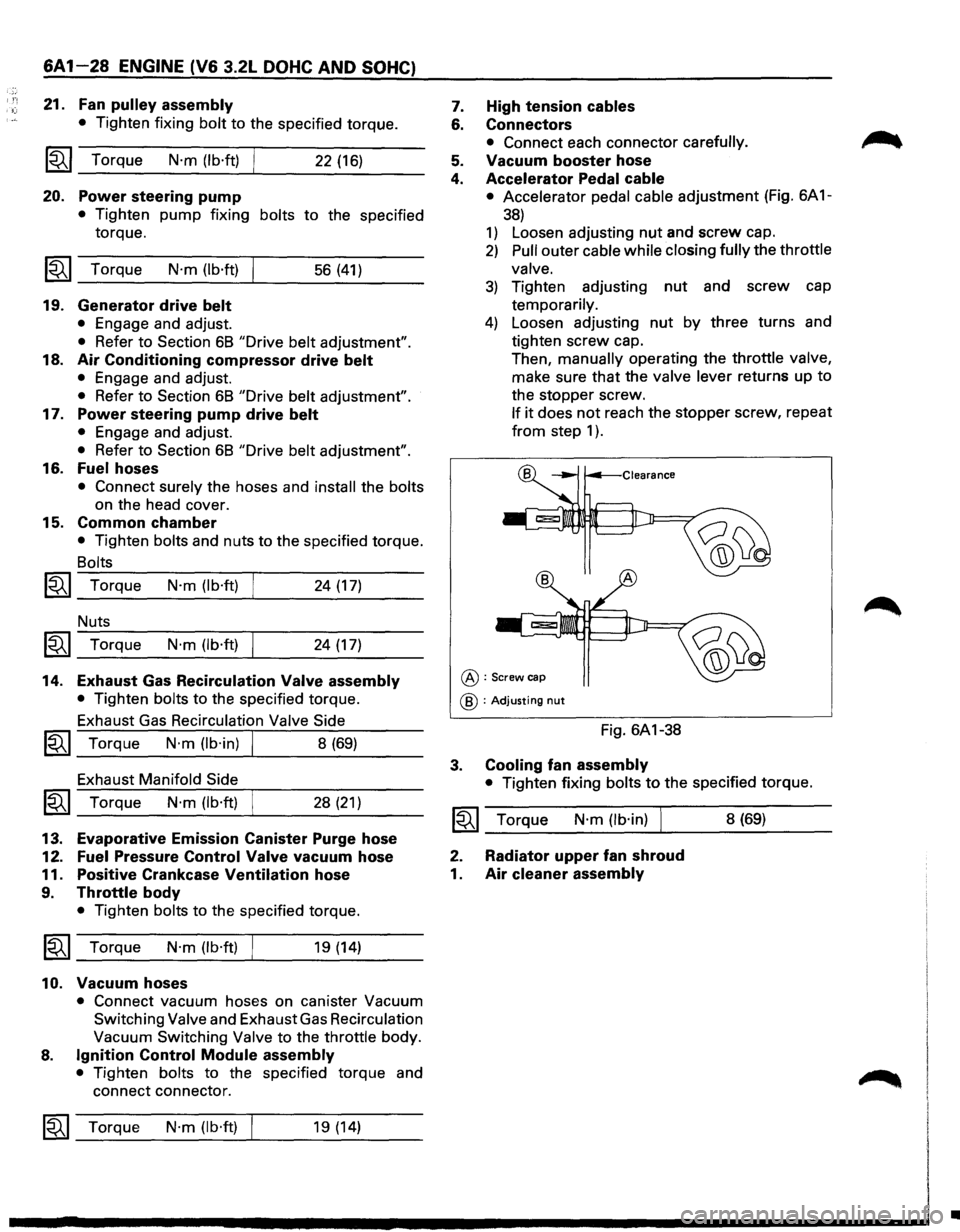
• Accelerator pedal cable adjustment (Fig. 6A 1-
38)
1) Loosen adjusting nut and screw cap.
2) Pull outer cable while closing fully the throttle
valve.
3) Tighten adjusting nut and screw cap
temporarily.
4) Loosen adjusting nut by three turns and
tighten screw cap.
Then,
manually operating the throttle valve,
make sure that the valve lever returns up to
the stopper screw.
If it does not reach the stopper screw, repeat
from step 1 ) .
@:Screw cap
@ :Adjusting nut
Fig. 6A1-38
3. Cooling fan assembly
• Tighten fixing bolts to the specified torque.
~~~ Torque N·m (lb·in) I 8 (69)
2. Radiator upper fan shroud
1. Air
cleaner assembly
•
Page 588 of 1928
6A1-30 ENGINE (V& 3.2L DOHC AND SOHC)
· ;~; E) REMOVAL
Preparation: Battery ground cable
1. Air cleaner assembly
2. Radiator upper fan shroud
• Remove from radiator.
3. Cooling fan assembly
• Remove four nuts, then the cooling fan
assembly.
4. Accelerator Pedal cable
• Disconnect from throttle body and cable
bracket.
5. Canister vacuum hose
• Disconnect from vacuum pipe.
6. Air vacuum hose
• Disconnect from common chamber.
7. Connectors
• Disconnect from Manifold Absolute, Canister
Vacuum Switching Valve
(VSV), Exhaust Gas
Recirculation
VSV, Intake Air Temperature and
ground cable.
8. High tension cables
• Disconnect from cylinder head cover.
9. Ignition Control Module assembly
• Disconnect three Electronic Ignition
connectors.
• Remove three Electronic Ignition bracket fixing
bolts, and remove Electronic
Ignition assembly
with high tension cables.
10. Throttle body
• Remove four fixing bolts.
11. Vacuum hoses
• Disconnect vacuum hoses on canisterVSVand
Exhaust
Gas Recirculation VSV from the
throttle body.
12. Positive Crankcase Ventilation hose
• Disconnect from common chamber.
13. Fuel Pressure Control Valve vacuum hose
• Disconnect from common chamber.
14. Evaporative Emission Canister Purge hose
• Disconnect from common chamber.
15. Exhaust Gas Recirculation Valve assembly
• Remove five bolts from common chamber,
exhaust manifold and cylinder head cover.
16. Common chamber duct
• Remove four bolts, four nuts and three bracket
fixing bolts, then remove the
common
chamber duct.
• Disconnect ground cable from rear side of
common chamber.
17. Common chamber
• Remove six bolts, two nuts and three bracket
fixing bolts, then remove the
common
chamber.
18. Fuel hoses
• Disconnect feed and return fuel hoses from fuel
pipes, and remove two bracket fixing bolts on
the cylinder head cover.
19. Power steering pump drive belt
20. Air Conditioning compressor drive belt
21. Generator drive belt
22. Power steering pump
23. Fan pulley assembly
24.
Crankshaft pulley assembly
1i0iJ • Using special tool J-8614-01, hold crankshaft
~ pulley.
•
Remove center bolt, then the pulley.
25. Oil cooler hose
• Remove two cooler hose bracket fixing bolts on
the timing belt cover.
26. Timing belt cover
27. Pusher
\fl CAUTION:
Yl The pusher prevents air from entering the oil
chamber.
Its rod must always be facing upward.
28. Timing belt
\fl CAUTIONS:
Yl 1) Do not bend or twist the belt, otherwise its
core could be damaged. The belt should
not
be bent at a radius less than 30mm.
2) Do not allow oil or other chemical substances
to come in contact
with the belt. They will
shorten the belt life.
3) Do not attempt to pry or stretch the belt with a
screwdriver
or any other tool during
installation.
4) Store timing belt in a cool and dark place.
Never expose the
belt to direct sunlight or
heat.
29. Cylinder head cover
• Remove 11 fixing bolts, then the cylinder head
cover.
30. Camshaft
• Camshaft pulley fixing bolt and camshaft pulley
•
Front plate fixing bolts and front plate
• Camshaft bracket fixing bolts and camshaft
31. Swing arm
• After removing the swing arm, attach a tag
showing the place
for swing arm.
32. Hydraulic lash adjuster (HLA)
• After removing the HLA, attach a tag showing
the place
for HLA.
\fl CAUTIONS:
Yl 1) Protect precision HLA from dust and foreign
materials.
2) Do not disassemble the HLA.
3) To clean the HLA, use a clean diesel oil.
•
Page 589 of 1928
I•• I INSTALLATION
32. Hydraulic lash adjuster (HLA)
• Install the HLA per removal mark.
31. Swing arm
• Install the swing arm per removal mark.
30. Camshaft
~ • Tighten camshaft bracket fixing bolts to the
~ specified torque.
~·
~·
Torque N-m (lb-in) I 10 (87)
Tighten front plate fixing bolts to the specified
torque.
Torque
N-m (lb·ft) I 19 (14)
Tighten camshaft pulley fixing bolts to the
specified torque.
Torque
N-m (lb·ft) I 63 (46)
29. Cylinder head cover
m • Clean the sealing surface of cylinder head and
l....al cylinder head cover to remove oil and sealing
I'Ei1 materials completely. Apply sealant (TB-1207B
La:.l or equivalent) of bead diameter 2-3 mm to four
places of arched area of camshaft brackets on
front and rear sides. (Fig. 6A 1-40)
Application points (Front and rear)
Fig. 6A1-40
~~~· Tighten bolts to the specified torque.
Torque
N·m (lb·in) I 8 (69)
28. Timing belt
• Refer to "Timing belt removal and installation"
in this section.
27. Pusher
• Tighten bolts to the specified torque.
~~~ Torque N-m (lb·ft) 19 (14)
ENGINE (V6 3.2L DOHC AND SOHC) 6A1-31
26. Timing belt cover
• Remove crankshaft pulley that was installed in
step
30.
~~~· Tighten bolts to the specified torque.
Torque
N·m (lb·ft) J 18 (13)
25. Oil cooler hose
~ • Tighten oil cooler hose bracket bolts to the
~ specified torque.
Torque
N-m (lb-ft) I 18 (13)
24. Crankshaft pulley assembly
• Using special tool J-8614-01, hold the
crankshaft
pulley.
~~~· Tighten center bolt to the specified torque.
Torque
N·m (lb·ft) I 167 (123)
23. Fan pulley assembly
~~~· Tighten fixing bolt to the specified torque.
Torque
N·m (lb-ft) I 22 (16)
22. Power steering pump
~ • Tighten pump fixing bolts to the specified
~ torque.
Torque
N-m (lb·ft) 46 (34)
21. Generator drive belt
• Engage and adjust.
• Refer to Section 6B "Drive belt adjustment".
20. Air Conditioning compressor drive belt
• Engage and adjust.
• Refer to Section 6B "Drive belt adjustment".
19. Power steering pump drive belt
• Engage and adjust.
• Refer to Section 6B "Drive belt adjustment".
18. Fuelhoses
• Connect the hoses securely and install the bolts
on the head cover.
17. Common chamber
~~~· Tighten bolts and nuts to the specified torque.
Bolts
Torque N·m (lb-ft) 24 (17)
Nuts
Torque
N-m (lb·ft) 24 (17)
16. Common chamber duct
~~~· Tighten bolts and nuts to the specified torque.
Bolts
Torque N·m (lb-ft) 24 (17)
Nuts
Torque
N-m (lb·ft) 24 (17)
• Connect the ground cable.
Page 592 of 1928
6A1-34 ENGINE (V6 3.2L DOHC AND SOHC)
1••1 REMOVAL
Preparation:
Battery ground cable
1. Air cleaner assembly
2. Radiator upper fan shroud
• Remove from radiator.
3. Cooling fan assembly
• Remove four nuts, then the cooling fan
assembly.
4. Accelerator Pedal cable
• Disconnect from throttle body and cable
bracket.
5. Canister vacuum hose
• Disconnect from vacuum pipe.
6. Vacuum booster hose
• Disconnect from common chamber.
7. Connectors
• Disconnect from Manifold Absolute Pressure,
canister Vacuum Switching Valve (VSV),
Exhaust Gas Recirculation VSV, Intake Air
Temperature and ground cable.
8. High tension cables
• Disconnect from cylinder head cover.
9. Ignition Control Module assembly
• Disconnect three Electronic Ignition con
nectors.
• Remove three Electronic Ignition bracket fixing
bolts, and remove Electronic Ignition assembly
with high tension cables.
10. Throttle body
• Remove four fixing bolts.
11. Vacuum hoses
• Disconnect vacuum hoses on canister VSV and
Exhaust Gas Recirculation
VSV from the
throttle body.
12. Positive Crankcase Ventilation hose
• Disconnect from common chamber.
13. Fuel Pressure Control Valve vacuum hose
• Disconnect from common chamber.
14. Evaporative Emission Canister Purge hose
• Disconnect from common chamber.
15. Exhaust Gas Recirculation Valve assembly
• Remove five bolts from common chamber,
exhaust manifold and cylinder head cover.
16. Common chamber duct
• Remove four bolts, four nuts and three bracket
fixing
bolts, then remove the common
chamber duct.
• Disconnect ground cable from rear side of
common chamber.
17. Common chamber
• Remove six bolts, two nuts and three bracket
fixing
bolts, then remove the common
chamber.
18. Fuel hoses
• Disconnect feed and return fuel hoses from fuel
pipes, and remove two bracket fixing bolts on
the cylinder head cover.
19. Power steering pump drive belt
20.
Air Conditioning compressor drive belt
21. Generator drive belt
22. Power steering pump
23.
Fan pulley assembly
24. Crankshaft pulley assembly
liQil • Using special tool J-8614-01, hold crankshaft
~ pulley.
• Remove center bolt, then the pulley.
25. Oil cooler hose
• Remove two cooler hose bracket fixing bolts on
the
timing belt cover.
26. Timing belt cover
27. Pusher
\fl CAUTION:
'V The pusher prevents air from entering the oil
chamber. Its rod must always be facing upward.
28. Timing belt
\fl CAUTIONS:
'V 1) Do not bend or twist the belt, otherwise its
core could be damaged. The
belt should not
be bent at a radius less than 30mm.
2) Do not allow oil or other chemical substances
to come in contact with the belt. They will
shorten the belt life.
3) Do not attempt to pry or stretch the belt with a
screwdriver or any other tool during
installation.
4) Store timing belt in a cool and dark place.
Never expose the
belt to direct sunlight or
heat.
29. Cylinder head cover
• Remove 11 fixing bolts, then the cylinder head
cover.
30. Camshaft timing pulley
31. Front plate
32. Camshaft brackets
33. Chain tensioner fixing
bolts
34. Camshaft
• Remove the camshaft with chain and chain
tensioner.
35. Oil seal and camshaft end plug
II