belt ISUZU TROOPER 1995 User Guide
[x] Cancel search | Manufacturer: ISUZU, Model Year: 1995, Model line: TROOPER, Model: ISUZU TROOPER 1995Pages: 1928
Page 130 of 1928
3-10 DIAGNOSIS
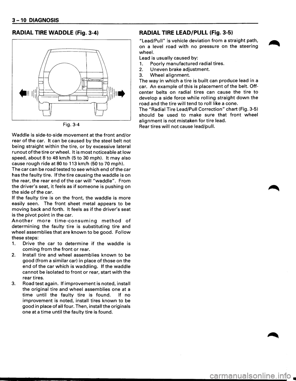
RADIAL TIRE WADDLE (Fig. 3-4)
Fig. 3-4
Waddle is side-to-side
movement at the front and/or
rear of the car. It can be caused by the steel belt not
being straight within the tire, or by excessive lateral
runout of the tire or wheel. It is most noticeable at low
speed, about 8 to 48 km/h (5 to 30 mph). It may also
cause
rough ride at 80 to 113 km/h (50 to 70 mph).
The car can be road tested
to see which end of the car
has
the faulty tire. If the tire causing the waddle is on
the rear, the rear end
of the car will "waddle". From
the
driver's seat, it feels as if someone is pushing on
the side
of the car.
If the faulty tire is on the front, the waddle is more
easily seen. The front sheet metal appears to be
moving back and forth. It feels as if the driver's seat
is
the pivot point in the car.
Another more time-consuming method of
determining the faulty tire is substituting tire and
wheel assemblies
that are known to be good. Follow
these steps:
1. Drive the car to determine if the waddle is
coming from the front or rear.
2. Install tire and wheel assemblies known to be
good (from a similar car) in place ofthose on the
end
of the car which is waddling. If the waddle
cannot be isolated to front or rear, start with the
rear tires.
3. Road test again. If improvement is noted, install
the original tire and wheel assemblies one at a
time until the faulty tire is found. If no
improvement is noted, install tires known to be
good in place of all four. Then, install the originals
one at a
time until the faulty tire is found.
RADIAL TIRE LEAD/PULL (Fig. 3-5)
"Lead/Pull" is vehicle deviation from a straight path,
on a level road
with no pressure on the steering
wheel.
Lead is usually caused by:
1. Poorly manufactured radial tires.
2. Uneven brake adjustment.
3. Wheel alignment.
The
way in which a tire is built can produce lead in a
car.
An example of this is placement of the belt. Off
center belts on radial tires can cause the tire to
develop a side force while rolling straight down the
road and the tire will tend to roll like a cone.
The
"Radial Tire Lead/Pull Correction" chart (Fig. 3-5)
should be used to make sure that front wheel
alignment is not mistaken for tire lead.
Rear
tires will not cause lead/pull.
II
Page 141 of 1928
POWER STEERING SYSTEM TEST
TEST PROCEDURE
Test of fluid pressure in the power steering system is
performed to determine whether
or not the oil pump
and
power steering unit are functioning normally.
The power steering system test is method used to
identify and
isolate hydraulic circuit difficulties. Prior
to performing this test, the following inspections and
corrections,
if necessary, must be made.
[!) INSPECT
• Pump reservoir for proper fluid level.
•
Pump belt for proper tension.
• Pump driver pulley condition.
1. Place a container under the pump to catch the
fluid when disconnecting or connecting the
hoses.
2. With the engine NOT running, disconnect the
pressure hose
at the power steering pump and
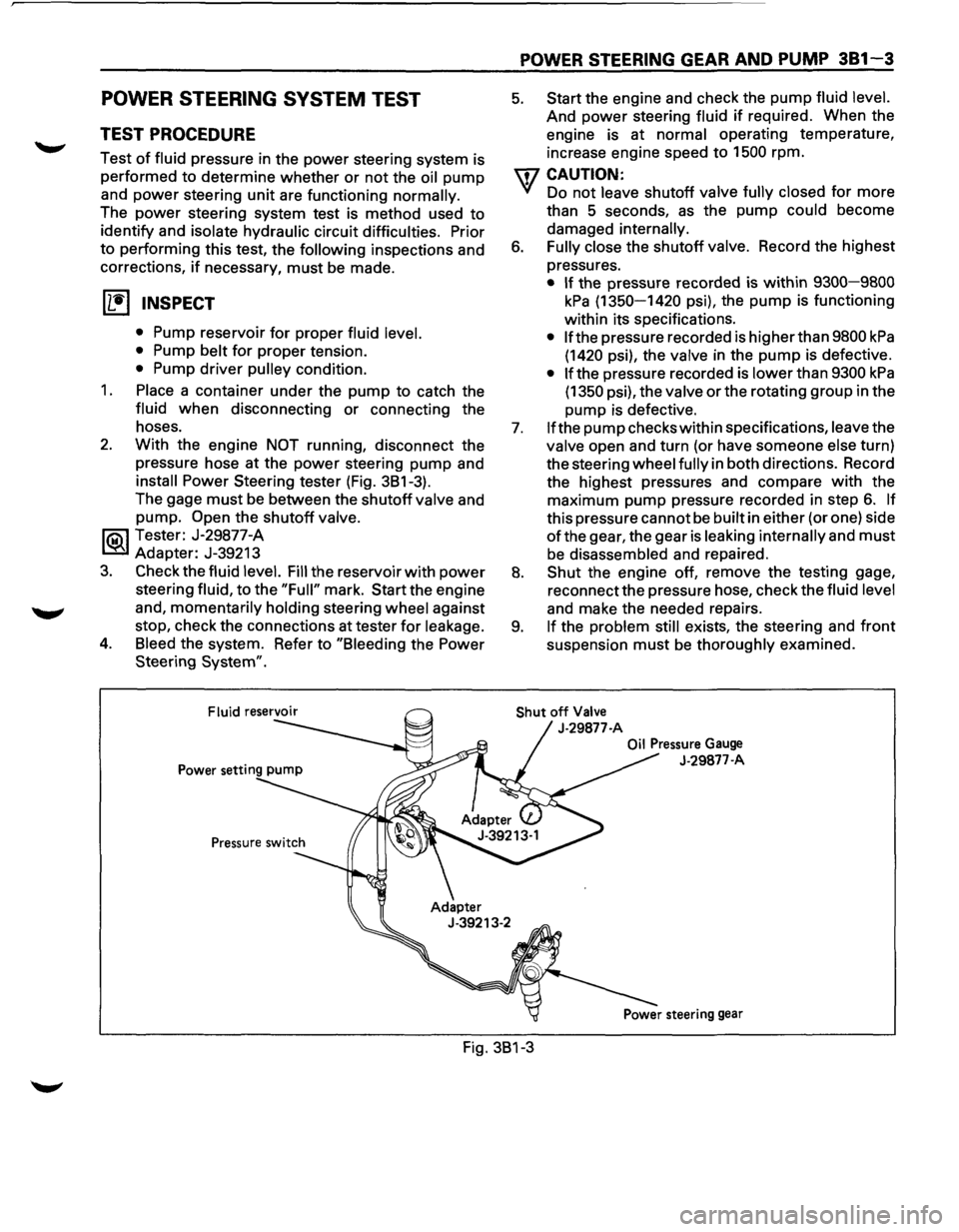
install Power Steering tester (Fig. 3B1-3).
The gage
must be between the shutoff valve and
pump.
Open the shutoff valve.
li5\l Tester: J-29877-A
~ Adapter: J-39213
3. Check the fluid level. Fill the reservoir with power
steering fluid, to the "Full" mark. Start the engine
and,
momentarily holding steering wheel against
stop, check the connections at tester
for leakage.
4. Bleed the system. Refer to "Bleeding the Power
Steering
System".
POWER STEERING GEAR AND PUMP 381-3
5. Start the engine and check the pump fluid level.
And power steering fluid if required. When the
engine is at
normal operating temperature,
increase engine speed to 1500 rpm.
U7 CAUTION:
VI Do not leave shutoff valve fully closed for more
than 5 seconds,
as the pump could become
damaged
internally.
6. Fully close the shutoff valve. Record the highest
pressures.
• If the pressure recorded is within 9300-9800
kPa (1350-1420 psi), the pump is functioning
within its specifications.
• If the pressure recorded is higher than 9800 kPa
(1420 psi), the valve in the pump is defective.
• If the pressure recorded is lower than 9300 kPa
(1350 psi), the valve or the rotating group in the
pump is defective.
7. If the pump checks within specifications, leave the
valve open and turn (or have someone else turn)
the steering
wheel fully in both directions. Record
the highest pressures and compare
with the
maximum pump pressure recorded in step
6. If
this pressure cannot be built in either (or one) side
ofthe gear, the gear is leaking internally and must
be disassembled and repaired.
8. Shut the engine off, remove the testing gage,
reconnect the pressure hose, check the
fluid level
and make the needed repairs.
9. If the problem still exists, the steering and front
suspension must be thoroughly examined.
Shut off Valve
J-29877-A
Oil Pressure Gauge
J-29877-A
Fig. 3B1-3
Page 142 of 1928
381 - 4 POWER STEERING GEAR AND PUMP
ON-VEHICLE SERVICE
MAINTENANCE
The hydraulic system should be kept clean and fluid
level in the reservoir should be checked at regular
intervals
and fluid added when required. Refer to
"MAINTENANCE AND LUBRICATION" in section OB
ofthe manual for type offluid to be used and intervals
for filling.
If the system contains some dirt, flush it as detailed
later
in this section. If it is exceptionally dirty, both the
pump and the gear must be completely disassembled
before further usage.
All tubes, hoses, and fittings should be inspected for
leakage at regular intervals. Fittings must be tight.
Make sure the clips, clamps and supporting tubes and
hoses are in
place and properly secured.
Power steering hoses and lines must not be twisted,
kinked or tightly bent. Air in the system will cause
spongy action and noisy operation. When a hose is
disconnected
or when fluid is lost, for any reason, the
system must be bled after refilling. Refer to "Bleeding
the Power Steering System" in this section.
FLUID LEVEL
1. Run the engine until the power steering fluid
reaches normal operating temperature, about
55°C (130°F), then shut the engine off.
2. Check the level of fluid in the reservoir.
3. If the fluid level is low, add power steering fluid
as specified in "MAINTENANCE AND LUBRI
CATION" in Section OB to the proper level and
install the receiver cap.
4. When checking the fluid level after the steering
system has been serviced,
air must be bled from
the system. Refer to "Bleeding the Power
Steering
System" in this section.
BLEEDING THE POWER STEERING
SYSTEM
When a power steering pump or gear has been
installed, or an oil line has been disconnected, the air
that has entered the system must be bled out before
the vehicle is operated. If air is allowed to remain in
the power steering fluid system, noisy and
unsatisfactory operation of the system may result.
BLEEDING PROCEDURE
When bleeding the system, and any time fluid is
added
to the power steering system, be sure to use
only power steering fluid as specified in
"MAINTENANCE AND LUBRICATION" in section OB.
1. Fill the pump fluid reservoir to the proper level
and let the fluid settle for at least two minutes.
2. Start the engine and let it run for a few seconds.
Do
not turn the steering wheel. Then turn the
engine off.
3. Add fluid if necessary.
4. Repeat the above procedure until the fluid level
remains constant after running the engine.
5. Raise the front end of the vehicle so that the
wheels are off the ground.
6. Start the engine. Slowly turn the steering wheel
right and left, lightly contacting the wheel stops.
7. Add power steering fluid if necessary.
8. Lower the vehicle and turn the steering wheel
slowly from lock to lock.
9. Stop the engine. Check the fluid level and refill
as required.
10.
If the fluid is extremely foamy, allow the vehicle
to stand a few minutes and repeat the above
procedure.
~ INSPECT
• Belt for tightness.
• Pulley for looseness or damage. The pulley
should not wobble with the engine running.
• Hoses so they are not touching any other parts
of the vehicle.
• Fluid level
and fill to the proper level.
FLUSHING THE POWER STEERING
SYSTEM
1. Raise the front end of the vehicle off the ground
until the wheels are free to turn.
2. Remove the fluid return line at the pump inlet
connector and plug the connector port on the
pump.
Position the line toward a large container to
catch the draining fluid.
3. While running the engine at idle, fill the reservoir
with new power steering fluid. Turn the steering
wheel in both directions. DO NOT contact wheel
stops or hold the wheel in a corner, or fluid will
stop and the pump will be in pressure relief mode.
A sudden
overflow from the reservoir may
develop if the wheel is held at a stop.
4. Install all the lines and hoses. Fill the system with
new power steering fluid and bleed the system
as described in "Bleeding The Power Steering
System". Operate the engine for about 15
minutes.
Remove the
pump return line at the pump inlet
and plug the connection on the pump. While
refilling the reservoir, check the draining fluid for
contamination. If foreign material is still evident,
replace all lines, disassemble and clean or replace
the power steering system components. Do not
re-use any drained power steering fluid.
~
~
Page 146 of 1928
381-8 POWER STEERING GEAR AND PUMP
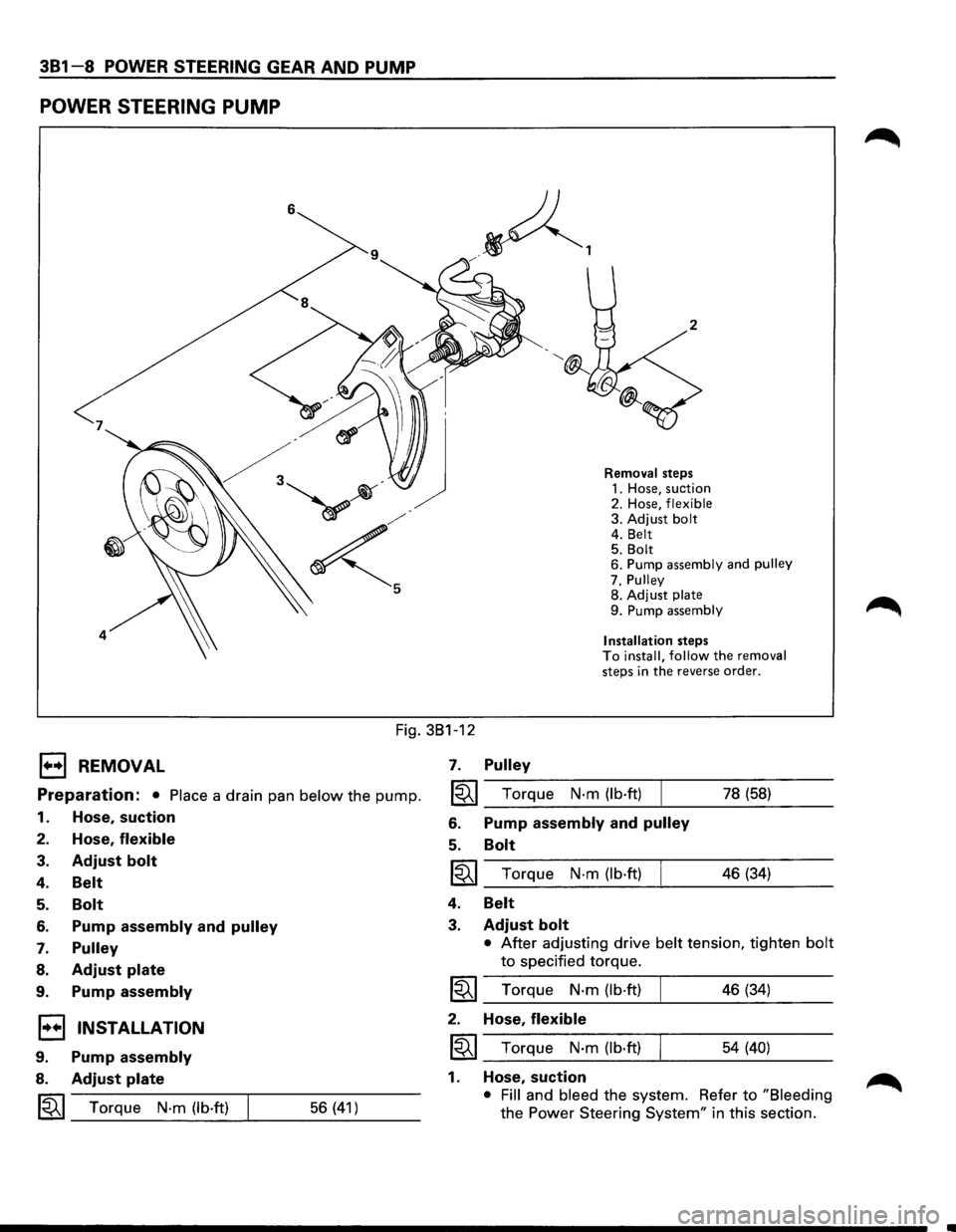
POWER STEERING PUMP
<
4
Removal steps
1. Hose, suction
2. Hose,
flexible 3. Adjust bolt 4. Belt 5. Bolt 6. Pump assembly and pulley
7. Pulley
8. Adjust
plate
9. Pump assembly
Installation
steps To install, follow the removal steps in the reverse order.
Fig. 381-12
B REMOVAL
Preparation: • Place a drain pan below the pump.
1. Hose, suction
2. Hose, flexible
3. Adjust bolt
4. Belt
5.
6.
7.
8.
9.
Bolt
Pump assembly and pulley
Pulley
Adjust plate
Pump assembly
1•+1 INSTALLATION
9. Pump assembly
8. Adjust plate
~~~ Torque N·m (lb·ft) 56 (41)
7. Pulley
~~~ Torque N·m (lb·ft)
6. Pump assembly and pulley
5. Bolt
~~~ Torque N·m (lb·ft)
4.
3.
Belt
Adjust bolt
78 (58)
46 (34)
• After adjusting drive belt tension, tighten bolt
to specified torque.
I~I_T_o_rq....:...u_e_N_·_m_(_lb_·ft_)____! ___ 4_6...:..(3_4...:_) __ _
2. Hose, flexible
~~~ Torque N·m (lb·ft) 54 (40)
1. Hose, suction
• Fill and bleed the system. Refer to "Bleeding
the Power Steering System" in this section.
Page 201 of 1928
WHEELS AND TIRES 3E-1
SECTION 3E
WHEELS AND TIRES
W CAUTION:
When fasteners are removed, always reinstall them at the same location from which they were removed.
If a fastener needs to be replaced, use the correct part number fastener for that application. If the correct
part
number fastener is not available, a fastener of equal size and strength (or stronger) may be used.
Fasteners
that are not reused, and those requiring thread locking compound, will be called out. The correct
torque value must be used when installing fasteners that require it. If the above conditions are not
followed, parts or system damage could result.
CONTENTS
General Description . . . . . . . . . . . . . . . . . . . . . . . . . . . . . . . 3 E -1 Unit Repair .......................................... 3E-7
Diagnosis ........................................... 3E-2 Tires ............................................... 3E-7
Irregular and Premature Wear ................ 3E-2 Wheels ............................................ 3E-7
Inflation of Tires ................................. 3 E- 3 General Balance Procedure ................... 3E-8
Diagnosis List. . . . . . . . . . . . . . . . . . . . . . . . . . . . . . . . . . . . 3 E- 3 Balancing Wheel and Tire ...................... 3E-8
On-Vehicle Service ................................ 3E-6 Main Data and Specifications .................... 3E-9
Wheels ............................................ 3E-6 General Specifications ......................... 3E-9
Torque Specifications .......................... 3E-9
GENERAL DESCRIPTION
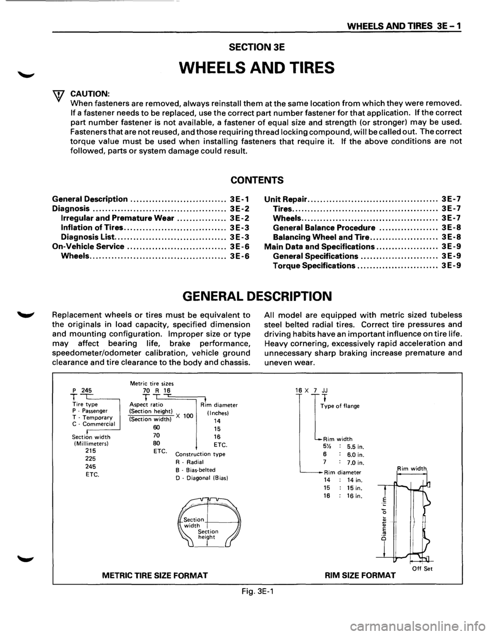
Replacement wheels or tires must be equivalent to
the originals in load capacity, specified dimension
and mounting configuration. Improper size or type
may affect bearing life, brake performance,
speedometer/odometer calibration, vehicle ground
clearance and tire clearance to the body and chassis.
p 245
T Tire type P -Passenger T -Temporary C -Commercial
Section
width (Millimeters) 215 225
245
ETC.
Metric tire sizes 70 R 16 T ,...
Aspect ratio I Rim diameter
(Section height)
(Section
width) X 100 (Inches)
14 60 70
80 ETC.
15
16 ETC.
Construction type
R-Radial
B - Bias-belted
D - Diagonal (Bias)
METRIC TIRE SIZE FORMAT
All model are equipped with metric sized tubeless
steel belted radial
tires. Correct tire pressures and
driving habits have an important influence on tire life.
Heavy cornering, excessively rapid acceleration and
unnecessary sharp braking increase
premature and
uneven wear.
16 X 7 JJ
I
~pe of flange
Rim width 5% 5.5 in.
6 6.0 in. 7 7.0 in.
Rim diameter Rim width
14 14 in. 15 15 in. 16 : 16 in.
I Off Set RIM SIZE FORMAT
Fig. 3E-1
Page 207 of 1928
WHEELS AND TIRES 3E-1
TIRES
REPLACEMENT
UNIT REPAIR
WHEELS
REPLACEMENT
When replacement is necessary, the original metric
the size should be used. Most metric tire sizes do not
have exact corresponding alphanumeric tire sizes. It
is recommended that new tires be installed in pairs on
the same axle. If necessary to replace only one tire, it
should be paired with tire having the most tread, to
equalize braking traction.
w CAUTION:
Do not mix different types of tires such as radial,
bias and bias-belted tires except in emergencies,
because
vehicle handling may be seriously
affected and may result in loss of control.
TIRE DISMOUNTING
Remove valve cap on valve step and deflate the tire.
Then use a
tire changing machine to mount or
dismount tires.
Follow the equipment manufacturer's instruction. Do
not use hand tools or tire lever alone to change tires
as they may damage the tire beads or wheel rim.
TIRE MOUNTING
Rim bead seats should be cleaned with a wire brush
....._., or coarse steel wool to remove lubricants, and light
rust. Before mounting a tire, the bead area should be
well lubricated with an approved tire lubricant.
After mounting, inflate the tire to 196kPa (28 psi) so
that beads are completely seated. Inflate the air to
specified pressure and install valve cap to the stem.
\f WARNING:
Never stand over tire when inflating. Bead may
break when bead snaps over rim's safety hump
and cause serious personal injury.
Never exceed
240 kPa (35 psi) pressure when
inflating. If 240 kPa (35 psi) pressure will not
seat beads, deflate, re-lubricate and re-inflate.
Over
inflation may cause the bead to break and
cause serious
personal injury.
TIRE REPAIR
There are many different materials on the market
used to repair tires.
Manufacturers have published detailed instructions
on how and when to repair tires. These instructions
can be obtained from the tire manufacturer if they are
not included with the repair kit. Damaged
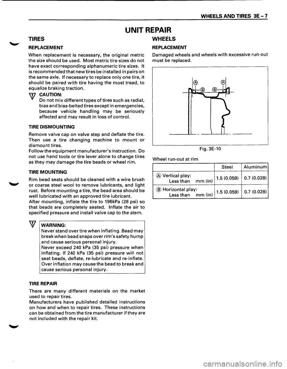
wheels and wheels with excessive run-out
must be replaced.
Fig. 3E-10
Wheel
run-out at rim
Steel Aluminum
@ Vertical play: 1.5 (0.059) 0.7
(0.028) Less than mm(in)
@ Horizontal play: 1.5 (0.059) 0.7
(0.028) Less than mm(in)
Page 509 of 1928
ENGINE DIAGNOSIS 6-11
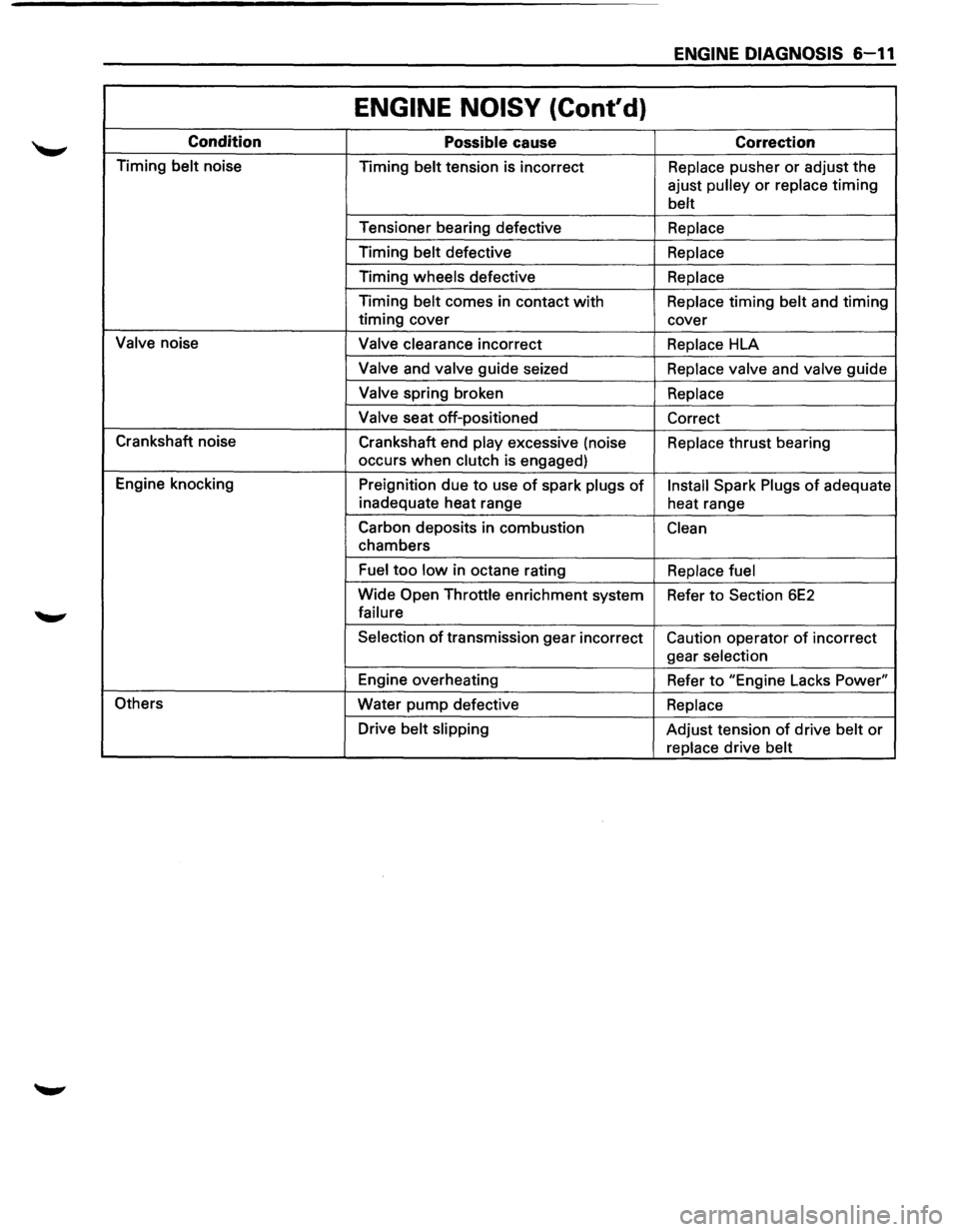
ENGINE NOISY (Cont'd)
Condition Possible cause Correction
Timing belt noise
Timing belt tension is incorrect Replace pusher or adjust the
ajust
pulley or replace timing
belt
Tensioner bearing defective Replace
Timing belt defective Replace
Timing wheels defective Replace
Timing belt comes in contact with Replace timing belt and timing
timing cover
cover
Valve noise Valve clearance incorrect Replace HLA
Valve and valve guide seized Replace valve and valve guide
Valve spring broken Replace
Valve
seat off-positioned
Correct
Crankshaft noise
Crankshaft end
play excessive (noise Replace thrust bearing
occurs
when clutch is engaged)
Engine knocking
Preignition due
to use of spark plugs of Install Spark Plugs of adequate
inadequate heat range
heat range
Carbon deposits in combustion
Clean
chambers
Fuel too low in octane rating Replace fuel
Wide Open Throttle enrichment system
Refer to Section 6E2
failure
Selection
of transmission gear incorrect Caution operator of incorrect
gear
selection
Engine overheating
Refer to "Engine Lacks Power"
Others Water
pump defective Replace
Drive belt slipping Adjust tension of drive belt or
replace drive belt
Page 559 of 1928
ENGINE (V6 3.2L DOHC AND SOHC) 6A 1-1
SECTION 6A1
3.2L V6 ENGINE
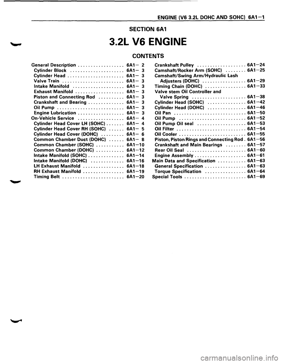
CONTENTS
General Description .................. 6A1-2 Crankshaft Pulley ................... 6A1-24
Cylinder Block . . . . . . . . . . . . . . . . . . . . . 6A 1-3 Camshaft/Rocker Arm (SOHC) ........ 6A1-25
Cylinder Head ...................... 6A1-3 Camshaft/Swing Arm/Hydraulic Lash
Valve Train ........................ 6A1-3 Adjusters (DOHC) ................. 6A1-29
Intake Manifold .................... 6A1-3 Timing Chain (DOHC) ................ 6A1-33
Exhaust Manifold ................... 6A1-3 Valve stem Oil Controller and
Piston and
Connecting Rod .......... 6A1-3 Valve Spring ..................... 6A1-38
Crankshaft and Bearing .............. 6A1-3 Cylinder Head (SOHC) ............... 6A1-42
Oil Pump .......................... 6A1-3 Cylinder Head (DOHC) ............... 6A1-46
Engine Lubrication . . . . . . . . . . . . . . . . . . 6A 1-3 Oil Pan ............................ 6A 1-50
On-Vehicle Service . . . . . . . . . . . . . . . . . . 6A1-4 Oil Pump .......................... 6A 1-52
Cylinder Head Cover LH (SOHC) ....... 6A1-4 Oil Pump Oil seal ................... 6A 1-53
Cylinder Head Cover RH (SOHC) ...... 6A1-5 Oil Filter ........................... 6A 1-54
Cylinder Head Cover (DOHC) . . . . . . . . . 6A 1-6 Oil Cooler .......................... 6A 1-55
Common Chamber Duct (DOHC) ...... 6A1-8 Piston, Piston Rings and Connecting Rod . 6A 1-56
Common Chamber (SOHC) ........... 6A1-10 Crankshaft and Main Bearings ........ 6A1-57
Common Chamber (DOHC) ........... 6A1-12 Rear Oil Seal ....................... 6A1-60
Intake Manifold (SOHC) .............. 6A1-14 Engine Assembly .................... 6A1-61
Intake Manifold (DOHC) ............. 6A1-16 Main Data and Specification ........... 6A1-63
LH Exhaust Manifold . . . . . . . . . . . . . . . . 6A 1-18 General Specification ................ 6A 1-63
RH Exhaust Manifold ................ 6A1-19 Torque Specification ................ 6A1-64
Timing Belt ........................ 6A1-20 Special Tools ........................ 6A1-69
Page 561 of 1928
CYLINDER BLOCK
The cylinder block is made of aluminum die-cast
casting
for 75° V-type six cylinders. It has a rear plate
integrated structure and employs a deep skirt. The
cylinder liner is cast and the liner inner diameter and
crankshaft
journal diameter are classified into grades.
The crankshaft is supported by four bearings
of which
width is different between No.2, No.3 and No.1, No.4;
the
width of No.3 bearing on the body side is different
in order
to support the thrust bearing. The bearing cap
is made
of nodular cast iron and each bearing cap uses
four bolts and two side bolts.
CYLINDER HEAD
The cylinder head, made of aluminum alloy casting
employs a pent-roof type combustion chamber with a
spark
plug in the center.
The intake and exhaust
valves are placed in V-type
design. The ports are cross-flow type.
VALVE TRAIN
SOHC: The camshafts on both banks are driven by a
timing
belt to operate the valves via rocker arm.
No
further valve clearance adjustment is
required, due
to the Hydraulic lash adjuster
attachedtotherockerarm.
DOHC: Intake camshaft on the both sides of banks are
driven through a
timing belt, while exhaust
camshaft are driven by the both sides
of intake
camshaft through chains.
The driven camshafts open and
close valves
through swing arms.
Valve clearance is automatically adjusted by
means
of HLA built in the cylinder head.
INTAKE MANIFOLD
SOHC: The intake manifold system is composed ofthe
aluminum cast common chamber and intake
manifold attached with six fuel injectors.
DOHC: The intake manifold system is composed of the
aluminum cast common chamber duct having
the induction
control valve, common chamber
and intake
manifold attached with six fuel
injectors.
EXHAUST MANIFOLD
The exhaust manifold is made of nodular cast iron.
PISTONS AND CONNECTING RODS
Aluminum pistons are used after selecting the grade
that meets the cylinder bore diameter. Each piston has
two compression rings and one oil ring. The piston pin
made
of chromium steel is offset 1 mm toward the
thrust side, and the thrust pressure
of piston to the
cylinder wall varies gradually as the piston travels. The
connecting rods are made
of forged steel. The
connecting rod bearings are graded
for correct size
selection.
ENGINE (V6 3.2L DOHC AND SOHC) 6A1-3
CRANKSHAFT AND BEARINGS
The crankshaft is made of Ductile cast-iron.Pins and
journals are graded for correct size selection for their
bearing.
OIL PUMP
The trochoid-type oil pump is driven by crankshaft.
Operation and service procedures are described in this
section.
ENGINE LUBRICATION
The oil discharged by a trochoid-type oil pump driven
by the crankshaft is fed through full-flow oil filter and
engine
coolant cooled oil cooler up to the oil gallery
provided under the crankshaft bearing cap. The oil is
then
led to the crankshaft journals and cylinder head.
The crank pins are
lubricated with oil from crankshaft
journals through oil holes. Also, an oil jet is fed to each
cylinder from crankshaft journals on the connecting
rod
for piston cleaning. The oil pan flange is sealed with
liquid packing only; do not deform or damage the
flange surface during removal or installation.
Page 578 of 1928
·,'
6A1-20 ENGINE (V6 3.2L DOHC AND SOHC)
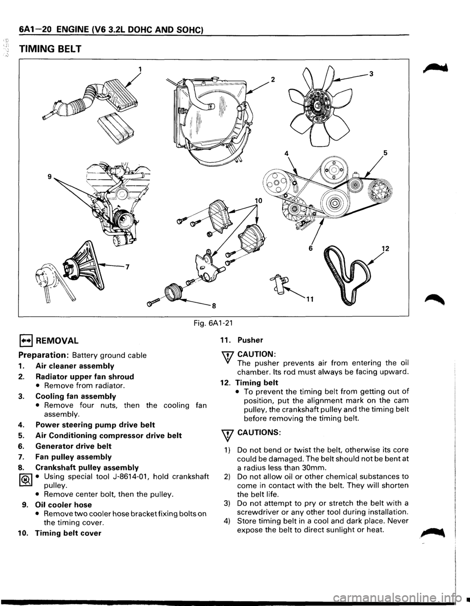
TIMING BELT
1 3
2
6 12
~ ..
Fig. 6A1-21
1••1 REMOVAL
Preparation: Battery ground cable
1. Air cleaner assembly
2. Radiator upper fan shroud
• Remove from radiator.
3. Cooling fan assembly
• Remove four nuts, then the cooling fan
assembly.
4. Power steering pump drive belt
5. Air Conditioning compressor drive belt
6. Generator drive belt
7. Fan pulley assembly
8. Crankshaft pulley assembly
~ • Using special tool J-8614-01, hold crankshaft
~ pulley.
•
Remove center bolt, then the pulley.
9. Oil cooler hose
• Remove two cooler hose bracket fixing bolts on
the timing cover.
10. Timing belt cover 11.
Pusher
'IT7 CAUTION:
'if The pusher prevents air from entering the oil
chamber. Its rod must always be facing upward.
12. Timing belt
• To prevent the timing belt from getting out of
position, put the alignment mark on the cam
pulley, the crankshaft pulley and the timing belt
before removing the timing belt.
w CAUTIONS:
1) Do not bend or twist the belt, otherwise its core
could be damaged. The belt should not be bent at
a radius
less than 30mm.
2) Do not allow oil or other chemica[ substances to
come in contact with the belt. They will shorten
the
belt life.
3) Do not attempt to pry or stretch the belt with a
screwdriver or any other tool during installation.
4) Store timing belt in a cool and dark place. Never
expose the
belt to direct sunlight or heat. ~
•