belt ISUZU TROOPER 1995 Repair Manual
[x] Cancel search | Manufacturer: ISUZU, Model Year: 1995, Model line: TROOPER, Model: ISUZU TROOPER 1995Pages: 1928
Page 639 of 1928
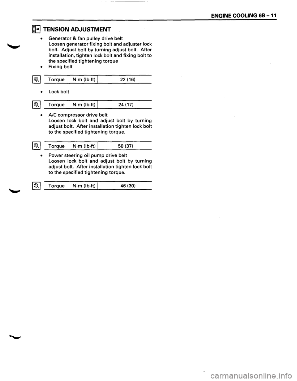
IE TENSION ADJUSTMENT
• Generator & fan pulley drive belt
Loosen generator fixing bolt and adjuster lock
bolt.
Adjust bolt by turning adjust bolt. After
installation, tighten lock bolt and fixing bolt to
the specified tightening torque
• Fixing bolt
~~~ Torque N·m (lb·ft) I 22 (16)
• Lock bolt
~~~ Torque N·m (lb.ft) I 24 (17)
• A/C compressor drive belt
Loosen lock bolt and adjust bolt by turning
adjust bolt. After installation tighten lock bolt
to the specified tightening torque.
~~~ Torque N·m (lb·ft) I 50 (37)
• Power steering oil pump drive belt
Loosen lock bolt and adjust bolt by turning
adjust bolt. After installation tighten lock bolt
to the specified tightening torque.
~~~ Torque N·m (lb·ft) I 46 (30)
ENGINE COOUNG 68 -11
Page 679 of 1928
CHARGING SYSTEM 603 -3
DIAGNOSIS
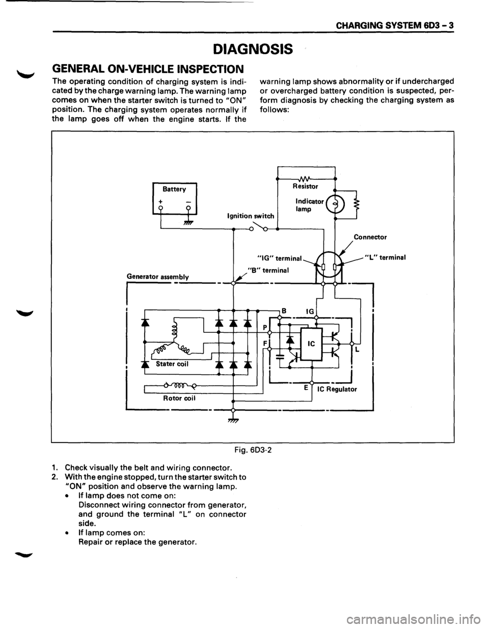
GENERAL ON-VEHICLE INSPECTION
The operating condition of charging system is indi
cated
by the charge warning lamp. The warning lamp
comes on when the starter switch is turned to "ON"
position. The charging system operates normally if
the lamp goes off when the engine starts. If the
Battery
+
warning lamp shows abnormality or if undercharged
or overcharged battery condition is suspected, per
form diagnosis by checking the charging system as
follows:
Resistor
Ignition switch
"B" terminal
Fig. 603-2
1. Check visually the belt and wiring connector.
2. With the engine stopped, turn the starter switch to
"ON" position and observe the warning lamp.
• If lamp does not come on:
Disconnect
wiring connector from generator,
and
ground the terminal "L" on connector
side.
• If lamp comes on:
Repair
or replace the generator.
Connector
"L" terminal
l
Page 681 of 1928
2,5 3
6 4
CHARGING SYSTEM 603 - 5
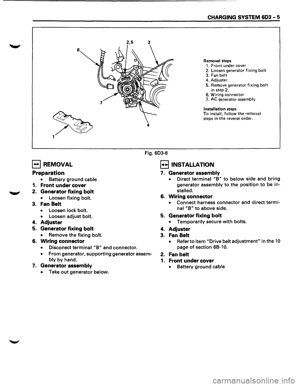
Removal steps
1. Front under cover
2. Loosen generator fixing bolt
3. Fan belt
4. Adjuster
5. Remove generator fixing bolt
in step 2. 6. Wiring connector
7. AC generator assembly
Installation steps To install, follow the removal
steps in
the reverse order.
Fig. 603-6
E] REMOVAL
Preparation
• Battery ground cable
1. Front under cover
2. Generator fixing bolt
• Loosen fixing bolt.
3. Fan Belt
• Loosen lock bolt.
•
Loosen adjust bolt.
4. Adjuster
5. Generator fixing bolt
• Remove the fixing bolt.
6. Wiring connector
• Disconect terminal "B" and connector.
• From generator, supporting generator assem
bly by hand.
7. Generator assembly
• Take out generator below.
EJ INSTALLATION
7. Generator assembly
• Direct terminal "B" to below side and bring
generator assembly to the position to be in
stalled.
6. Wiring connector
• Connect harness connector and direct termi
nal "B" to above side.
5. Generator fixing bolt
• Temporarily secure with bolts.
4. Adjuster
3. Fan Belt
• Refer to item "Drive belt adjustment" in the 10
page of section 6B-1 0.
2. Fan belt
1. Front under cover
• Battery ground cable
Page 734 of 1928
6E2-38 DRIVEABILITV AND EMISSIONS
CHART A-1
WILL NOT FLASH DIAGNOSTIC TROUBLE CODE (DTC) 12
NO "CHECK ENGINE" MALFUNCTION INDICATOR LAMP (MIL)
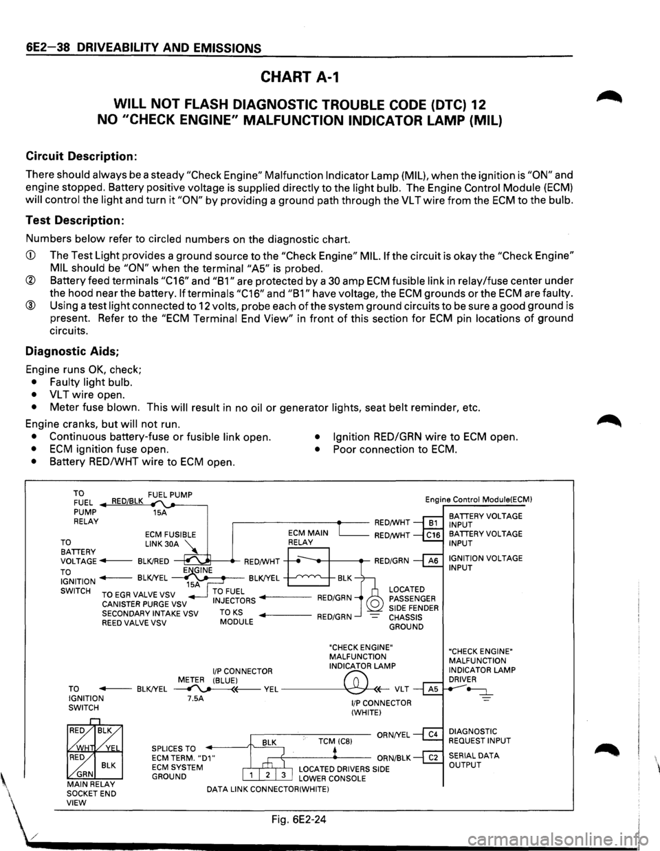
Circuit Description:
There should always be a steady "Check Engine" Malfunction Indicator Lamp (MIL), when the ignition is "ON" and
engine stopped. Battery positive
voltage is supplied directly to the light bulb. The Engine Control Module (ECM)
will control the light and turn it "ON" by providing a ground path through the VL T wire from the ECM to the bulb.
Test Description:
Numbers below refer to circled numbers on the diagnostic chart.
CD The Test Light provides a ground source to the "Check Engine" MIL. If the circuit is okay the "Check Engine"
MIL should
be "ON" when the terminai"A5" is probed.
® Battery feed terminals "C16" and "B1" are protected by a 30 amp ECM fusible link in relay/fuse center under
the hood near the battery.
If terminals "C16" and "B1" have voltage, the ECM grounds or the ECM are faulty.
® Using a test light connected to 12 volts, probe each of the system ground circuits to be sure a good ground is
present. Refer to the
"ECM Terminal End View" in front of this section for ECM pin locations of ground
circuits.
Diagnostic Aids;
Engine runs OK, check;
• Faulty light bulb.
•
VL T wire open.
• Meter fuse blown. This will result in no oil or generator lights, seat belt reminder, etc.
Engine cranks, but
will not run.
• Continuous battery-fuse or fusible link open. • Ignition RED/GRN wire to ECM open.
• ECM ignition fuse open. • Poor connection to ECM.
• Battery RED/WHT wire to ECM open.
TO FUEL .._..,==~ ,__,__-----, PUMP 15A
RELAY .--------~~-RED/WHT Engine
Control
Module(ECM)
BATIERY VOLTAGE
INPUT
ECM FUSIBLE RED/WHT TO LINK 30A '\.. BATIERY ~ VOLTAGE---BLK!RED ~---.-RED/WHT
TO IGNITION - BLK!YEL ~~~-BLK!YEL --'--'~"'---..__
SWITCH TO EGR VALVE VSV
CANISTER PURGE VSV
SECONDARY INTAKE VSV
REED VALVE VSV TO KS MODULE
LOCATED
PASSENGER
SIDE FENDER CHASSIS GROUND
"CHECK ENGINE"
MALFUNCTION
I/P CONNECTOR INDICATOR LAMP
METER (BLUE)
("";:; TO - BLK!YEL ~(---VEL~(;-VLT IGNITION 7.5A SWITCH
BLK ~ GRN MAIN RELAY
SOCKETEND SPLICES
TO ECM TERM. "D1" ECM SYSTEM GROUND
DATA
LINK CONNECTOR(WHITE)
1/P CONNECTOR
(WHITE)
BA TIERY VOLTAGE INPUT
IGNITION
VOLTAGE INPUT
"CHECK ENGINE"
MALFUNCTION
INDICATOR
LAMP DRIVER
~
DIAGNOSTIC REQUEST INPUT
' VIEW Fig. 6E2-24
./ .................................... __________________________ _
Page 1191 of 1928

CHASSIS ELECTRICAL 8-1
·SECTION 8
CHASSIS ELECTRICAL
'\f CAUTION: .
When fasteners are removed, always reinstall them at the same location from which they were removed.
If a fastener needs to be replaced, use the correct part number fastener for that application. If the correct
part number fastener is not
available, a fastener of equal size and strength (or stronger) may be used.
Fasteners that are not reused, and those requiring thread
locking compound, will be called out. The correct
torque
values must be used when installing fasteners that require it. If the above conditions are not
followed, parts or system damage could result.
CONTENTS
General Information .................................... 8-2
Notes for Working on Electrical
Items .................................................... 8-2
Symbols and Abbreviations ................. 8-8
Symbols ............................................ 8-8
Abbreviations ................................... 8-9
Parts for Electrical Circuit ..................... 8-10
Wiring ............................................... 8-10
Fuse .................................................. 8-11
Fusible Link ....................................... 8-12
Circuit Breaker ................................... 8-12
Relay ................................................. 8-12
Relay Specifications and
Configurations ................................ 8-13
Diode ................................................. 8-14
Connector ......................................... 8-15
Reading the Circuit Diagram ................ 8-17
Main Data and Specifications .................... 8-19
Bulb Specifications ................................ 8-19
Fuse,
Fusible Link and
Circuit Breaker Location ..................... 8-21
Fuse
Block Circuit .................................. 8-22
Reference Table of Fuse, Fusible
Link and Circuit Breaker ..................... 8-23
Relay Location ....................................... 8-27
Diode Location .......................................
8-28
Grounding Point .................................... 8-29
Reference Table ................................ 8-29
Location ............................................ 8-31
Cable Harness Routing .......................... 8-34
System Repair .............................................. 8-38
Start and Charging ................................ 8-38
Engine Control Module
(ECM) ................................................... 8-47
Headlight and Fog Light ........................ 8-58
Front Side Marker Light, Parking Light,
Taillight, License Plate Light and
Illumination Light .............................. 8-76
Stoplight and Rear Defogger .............. 8-92
Turn Signal Light, Hazard
Warning
Light, Cornering Light,
Backup
Light and Horn ..................... 8-106
Dome Light, Luggage room Light,
Courtesy Light, Map Light,
Seat Belt Switch and
Warning Buzzer ................................. 8-128
Power Door Lock ................................. 8-142
Power
Window .................................... 8-156
Cruise
Control ...................................... 8-172
Anti-Lock Brake
System (ABS) ........... 8-178
Rear
Wheel Anti-Lock Brake
System (RWAL) ................................. 8-185
Transmission
Control Module
(TCM) ................................................. 8-192
A/T Shift Lock ...................................... 8-200
Windshield
Wiper/Washer and
Rear
Wiper/Washer .......................... 8-205
Headlight wiper /washer ..................... 8-232
Audio, Auto Antenna,
Cigarette
Lighter and digital clock ... 8-246
Power Door Mirror ............................... 8-254
Anti-theft System ................................ 8-270
Meter and Warning/Indicator Light ... 8-288
A/T Shift Indicator ............................... 8-336
Heater and
Air Conditioning ............... 8-340
Sun
Roof ............................................... 8-346
Power Seat ........................................... 8-360
Seat
Heater .......................................... 8-37 4
Supplemental Restraint
System (SRS) -AIR BAG ................... 8-382
Page 1210 of 1928
8-20 CHASSIS ELECTRICAL
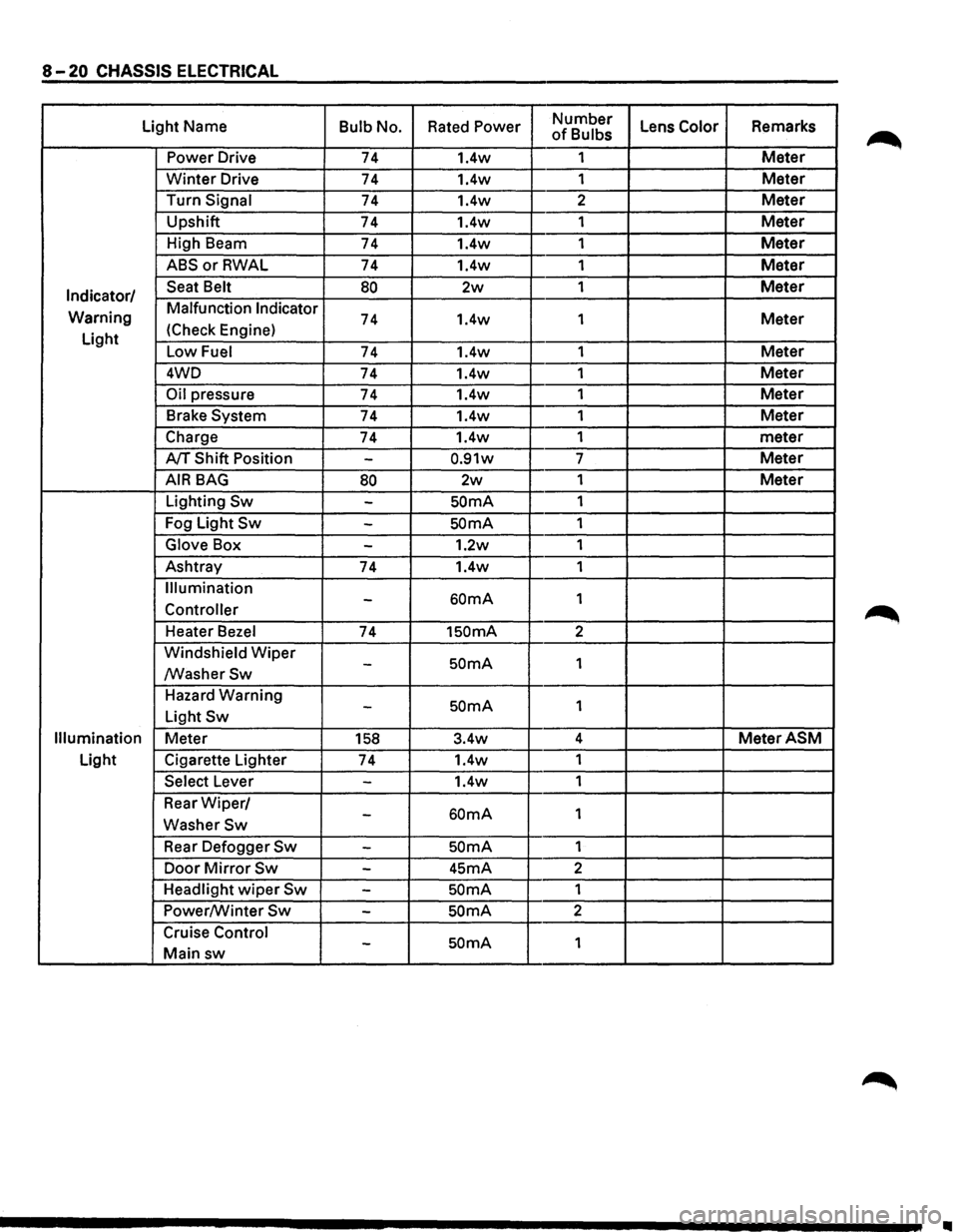
Light Name Bulb No. Rated Power Number Lens Color Remarks of Bulbs
Power Drive 74 1.4w 1
Meter
Winter Drive 74 1.4w
1 Meter
Turn Signal 74 1.4w 2 Meter
Upshift
74 1.4w 1 Meter
High Beam
74 1.4w 1 Meter
ABSorRWAL 74 1.4w 1 Meter
Indicator/ Seat Belt 80 2w 1 Meter
Warning Malfunction Indicator 74 1.4w
1 Meter
Light (Check
Engine)
Low Fuel 74 1.4w 1 Meter
4WD
74 1.4w 1 Meter
Oil pressure 74 1.4w 1 Meter
Brake System 74 1.4w 1 Meter
Charge 74 1.4w 1
meter
A/T Shift Position -0.91w 7 Meter
AIR BAG 80 2w 1 Meter
Lighting Sw -SOmA 1
Fog Light
Sw -SOmA 1
Glove Box -1.2w 1
Ashtray
74 1.4w 1
Illumination
60mA 1 -Controller
Heater Bezel 74 1SOmA 2
Windshield
Wiper SOmA 1 -/WasherSw
Hazard Warning SOmA 1 -Light Sw
Illumination Meter 158 3.4w 4 MeterASM
Light
Cigarette Lighter
74 1.4w
1
Select Lever -1.4w 1
Rear
Wiper/ 60mA 1 -WasherSw
Rear Defogger Sw -SOmA 1
Door
Mirror Sw -45mA 2
Headlight
wiper Sw -SOmA 1
Power/Winter
Sw -SOmA 2
Cruise Control
SOmA 1 -Main sw
II
Page 1214 of 1928
8-24 CHASSIS ELECTRICAL
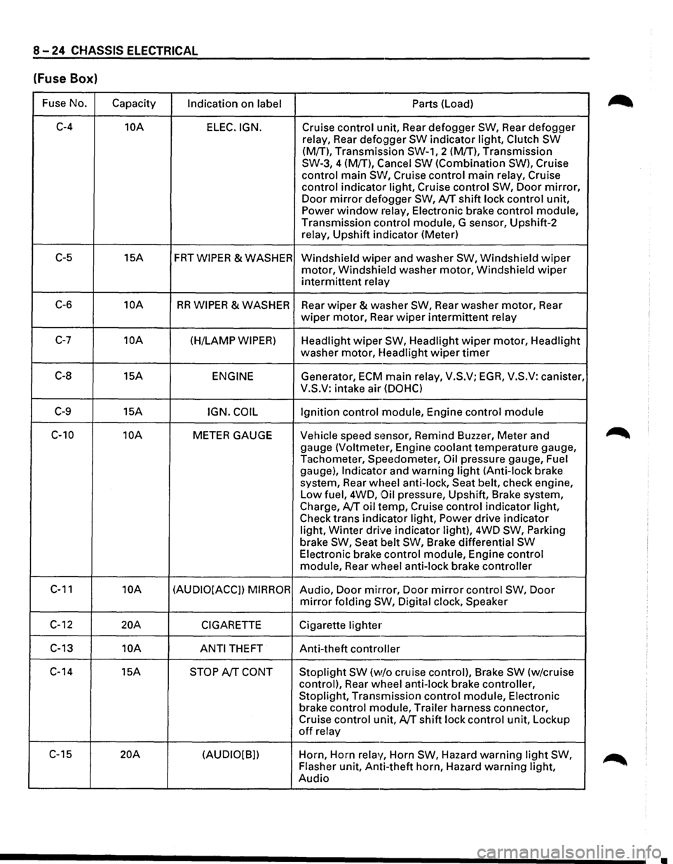
(Fuse Box)
Fuse No.
Capacity Indication on label Parts (Load)
C-4 10A
ELEC.IGN. Cruise control unit, Rear defogger SW, Rear defogger
relay, Rear
defo9ger SW indicator light, Clutch SW
(M{T), Transmission SW-1, 2 (M!T), Transmission
SW-3, 4 (M{T), Cancel
SW (Combination SW), Cruise
control main
SW, Cruise control main relay, Cruise
control indicator light, Cruise control
SW, Door mirror,
Door mirror defogger SW, AfT shift lock control unit,
Power window relay, Electronic brake control module,
Transmission control module, G sensor, Upshift-2
relay, Upshift indicator (Meter)
C-5 15A FRTWIPER &WASHER
Windshield wipt~r and washer SW, Windshield wiper
motor, Windshit~ld washer motor, Windshield wiper
intermittent relay
C-6 10A RR WIPER & WASHER
Rear wiper & washer SW, Rear washer motor, Rear
wiper motor, Rear wiper intermittent relay
C-7 10A (H/LAMP WIPER) Headlight wiper SW, Headlight wiper motor, Headlight
washer motor, Headlight
wiper timer
C-8 15A ENGINE Generator, ECM main relay, V.S.V; EGA, V.S.V: canister,
V.S.V: intake air
(DOHC)
C-9 15A IGN. COIL Ignition control module, Engine control module
C-10 10A METER GAUGE Vehicle speed stmsor, Remind Buzzer, Meter and
gauge
(Voltmeter, Engine coolant temperature gauge,
Tachometer, Speedometer,
Oil pressure gauge, Fuel
gauge),
Indicator and warning light (Anti-lock brake
system, Rear wheel anti-lock, Seat belt, check engine,
Low fuel, 4WD,
Oil pressure, Upshift, Brake system,
Charge,
AfT oil temp, Cruise control indicator light,
Check trans indicator light,
Power drive indicator
light,
Winter drive indicator light), 4WD SW, Parking
brake SW, Seat belt SW, Brake differential SW
Electronic brake control module, Engine control
module, Rear wheel anti-lock brake controller
C-11 10A (AUDIO[ACCJ) MIRROR Audio, Door mirror, Door mirror control SW, Door
mirror folding SW, Digital clock, Speaker
C-12 20A CIGARETTE Cigarette lighter
C-13 10A
ANTI THEFT Anti-theft controller
C-14 15A
STOP AfT CONT Stoplight SW (w/o cruise control), Brake SW (w/cruise
control), Rear wheel anti-lock brake controller,
Stoplight, Transmission control module, Electronic
brake control module, Trailer harness connector,
Cruise control unit,
AfT shift lock control unit, Lockup
off relay
C-15
20A (AUDIO[B]) Horn,
Horn relay, Horn SW, Hazard warning light SW,
Flasher unit, Anti-theft horn, Hazard warning light,
Audio
•
Page 1215 of 1928
CHASSIS ELECTRICAL 8-25
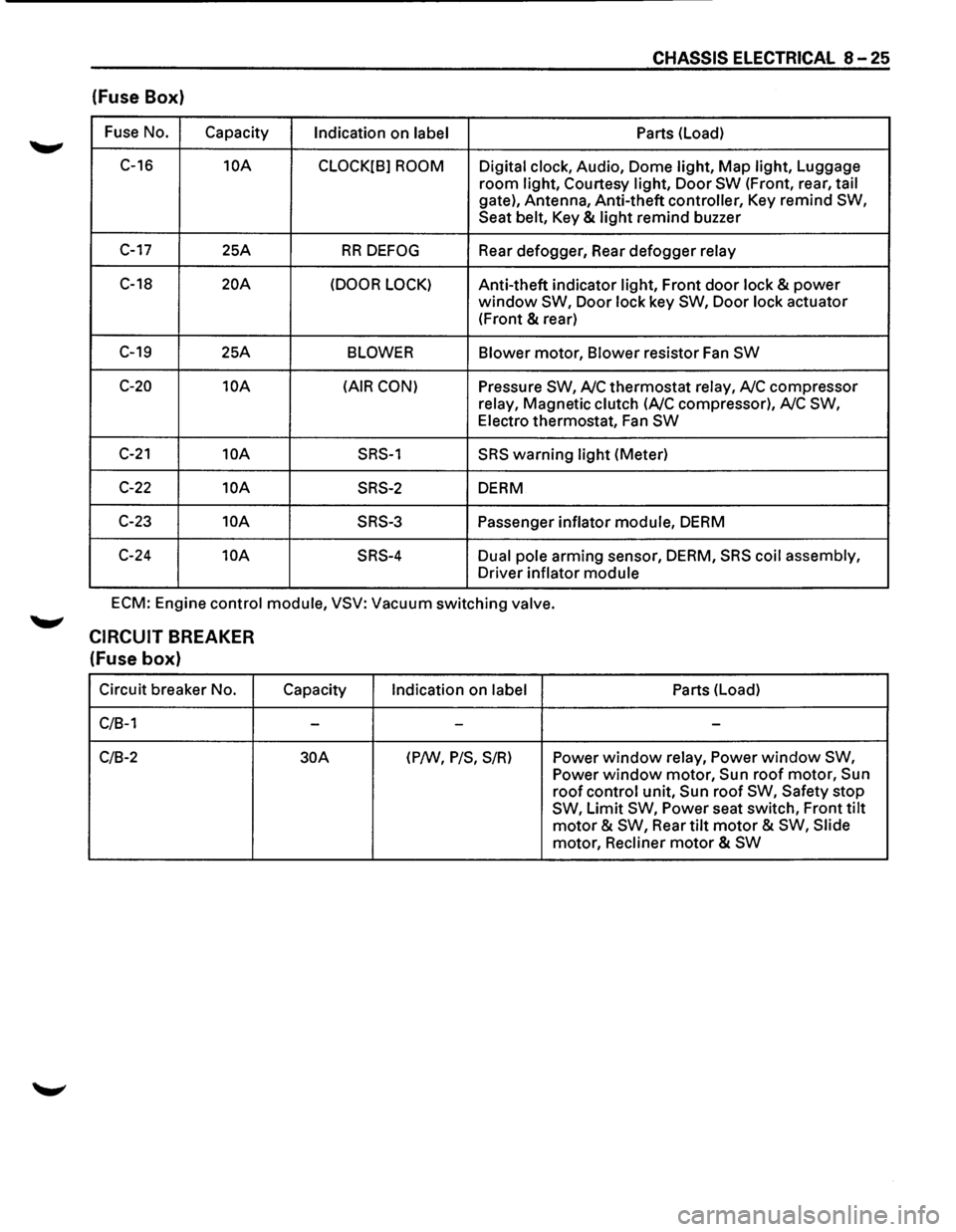
(fuse Box)
Fuse No.
Capacity Indication on label Parts
(Load)
C-16
10A
CLOCK[B] ROOM Digital clock, Audio, Dome light, Map light, Luggage
room light, Courtesy light, Door SW (Front, rear, tail
gate), Antenna, Anti-theft controller, Key remind SW,
Seat belt, Key & light remind buzzer
C-17 25A RR DEFOG Rear defogger, Rear defogger relay
C-18 20A (DOOR LOCK) Anti-theft indicator light, Front door lock & power
window SW, Door lock key SW, Door lock actuator
(Front
& rear)
C-19 25A BLOWER Blower motor, Blower resistor Fan SW
C-20 10A (AIR CON) Pressure SW, A/C thermostat relay, A/C compressor
relay, Magnetic clutch
(A/C compressor), A/C SW,
Electro thermostat, Fan SW
C-21 10A SRS-1 SRS warning light (Meter)
C-22 10A SRS-2 DERM
C-23
10A SRS-3 Passenger inflator module, DERM
C-24
10A SRS-4 Dual pole arming sensor, DERM, SRS coil assembly,
Driver inflator module
ECM: Engine control module, VSV: Vacuum switching valve.
CIRCUIT BREAKER
(fuse box)
Circuit breaker No.
C/B-1
C/B-2
Capacity
-
30A
Indication on label
-
(P/W, P/S, S/R)
Parts (Load)
-
Power window relay, Power window SW,
Power window motor, Sun roof motor, Sun
roof control unit, Sun roof SW, Safety stop
SW, Limit SW, Power seat switch, Front tilt
motor & SW, Rear tilt motor & SW, Slide
motor, Recliner
motor & SW
Page 1219 of 1928
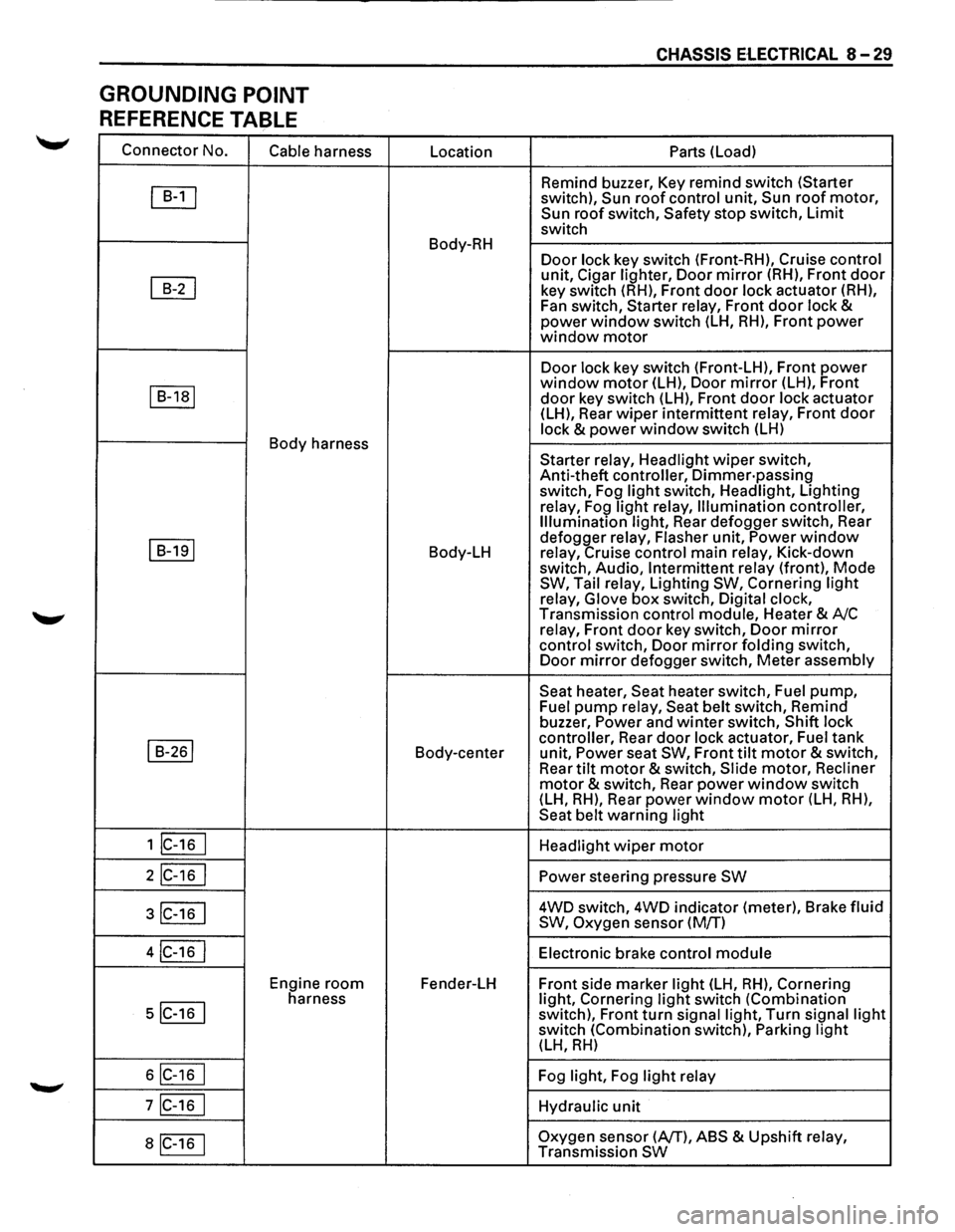
GROUNDING POINT
REFERENCE TABLE
Connector No.
Cable harness
~
~
I B-1a1
Body harness
I B-191
I B-261
1 lc-16 I
2IC-16 I
3IC-16 I
4IC-16 I
Engine room
5IC-16 I
harness
6IC-16 I
7IC-16 I
aiC-16 1
Location
Body-RH
Body-LH
Body-center
Fender-LH
CHASSIS ElECTRICAL 8-29
Parts (Load)
Remind buzzer, Key remind switch (Starter
switch),
Sun roof control unit, Sun roof motor, Sun roof switch, Safety stop switch, Limit
switch
Door lock key switch (Front-RH), Cruise control
unit, Cigar lighter, Door mirror (RH), Front door
key switch (RH), Front door lock actuator (RH),
Fan switch, Starter relay, Front
door lock & power window switch (LH, RH), Front power window motor
Door lock key switch (Front-LH), Front power window motor (LH), Door mirror (LH), Front
door key switch (LH), Front door lock actuator
(LH), Rear wiper intermittent relay, Front door
lock & power window switch (LH)
Starter relay, Headlight
wiper switch,
Anti-theft controller,
Dimmer·passing switch, Fog light switch, Headlight, Lighting
relay, Fog
light relay, Illumination controller,
Illumination light, Rear defogger switch, Rear
defogger relay, Flasher unit,
Power window relay, Cruise control main relay, Kick-down
switch, Audio, Intermittent relay (front), Mode SW, Tail relay, Lighting SW, Cornering light
relay, Glove box switch, Digital clock,
Transmission control module, Heater & A/C
relay, Front
door key switch, Door mirror
control switch, Door mirror folding switch,
Door mirror defogger switch, Meter assembly
Seat heater, Seat heater switch, Fuel pump, Fuel pump relay, Seat belt switch, Remind
buzzer, Power and winter switch, Shift lock
controller, Rear
door lock actuator, Fuel tank
unit, Power seat SW, Front tilt motor & switch,
Rear tilt motor & switch, Slide motor, Recliner
motor & switch, Rear power window switch
(LH, RH), Rear power window motor (LH, RH),
Seat belt warning light
Headlight
wiper motor
Power steering pressure SW
4WD switch, 4WD indicator (meter), Brake fluid
SW, Oxygen sensor (M/T)
Electronic brake control
module
Front side marker light (LH, RH), Cornering
light, Cornering light switch (Combination
switch), Front turn signal light, Turn signal light switch (Combination switch), Parking light (LH, RH)
Fog light, Fog light relay
Hydraulic
unit
Oxygen sensor (AfT), ABS & Upshift relay,
Transmission SW
Page 1318 of 1928
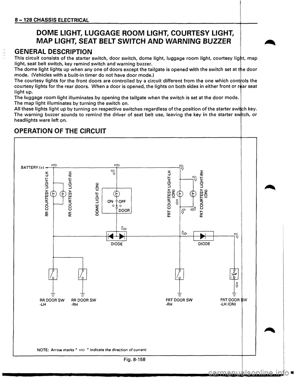
8-128 CHASSIS ELECTRICAL
DOME LIGHT, LUGGAGE ROOM LIGHT, COURTESY LIGHT,
MAP LIGHT, SEAT BELT SWITCH AND WARNING BUZZER
GENERAL DESCRIPTION
This circuit consists of the starter switch, door switch, dome light, luggage room light, courtesy lig t, map
light, seat belt switch, key remind switch and warning buzzer.
The dome
light lights up when any one of doors except the tailgate is opened with the switch set at t e door
mode. (Vehicles with a built-in timer do not have door mode.) !
The courtesy lights for the front doors are controlled by a circuit different from the one which cont ols the
courtesy
lights for the rear doors. When a door is opened, the lights on both sides in either front or r ar seat
light up.
The
luggage room light illuminates by opening the tailgate when the switch is set at the door mode.
The
map light illuminates by turning the switch on.
All these lights light up by turning on respective switches regardless of the position of the starter swi ch key.
The
warning buzzer sounds to remind the driver of seat belt use, leaving the key in the starter sv.. tch, or
headlights were left on.
OPERATION OF THE CIRCUIT
BATIERY (+) _....,.=>..:.__ _________ =>~---------lij
l} :X: :X: ...J a: ~ ~ :X: :X: Q .....__ (.!) ...J :J
~~ ®~ II: li: :::> r----:::> 0 0 u u a: a:
a: a:
z Q r---t----,
~ Go (.!) :J w ON OFF 0 0
~ DOOR 0 '-----+------'
~----------~~~~~~~~lr-l ____________ ,_b __ +-~~~-'--~'---,~ II...... 111"""11 Ill"""' J
-:..._ -=-
RRDOORSW RRDOORSW -LH -RH
DIODE DIODE
-=
FRTDOOR SW -RH
NOTE: Arrow marks u =:> H indicate the direction of current
Fig. 8-158
FRTDOOR W -LH (ON)
•