heating ISUZU TROOPER 1995 Owner's Manual
[x] Cancel search | Manufacturer: ISUZU, Model Year: 1995, Model line: TROOPER, Model: ISUZU TROOPER 1995Pages: 1928
Page 49 of 1928
HEATING AND VENTILATION 1A-19
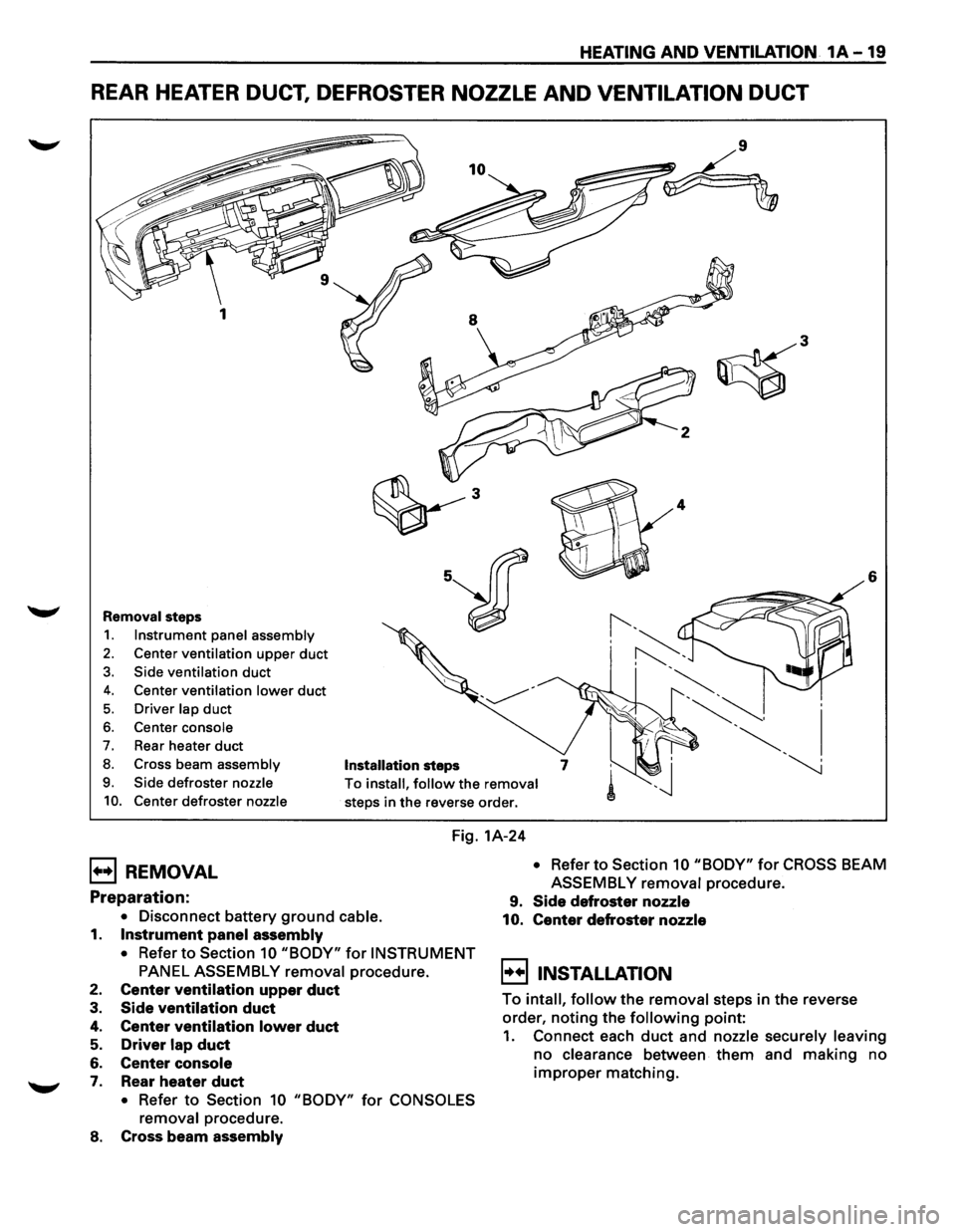
REAR HEATER DUCT, DEFROSTER NOZZLE AND VENTILATION DUCT
6
Removal steps
1. Instrument panel assembly
2. Center ventilation upper duct
3. Side ventilation duct
4. Center ventilation lower duct
5. Driver lap duct
6. Center console
7. Rear heater duct
8. Cross beam assembly Installation steps
9. Side defroster nozzle
10. Center defroster nozzle
To install, follow the removal
steps in the reverse order.
Fig. 1A-24
B REMOVAL
Preparation:
• Disconnect battery ground cable.
1. Instrument panel assembly
• Refer to Section 10 "BODY" for INSTRUMENT
PANEL ASSEMBLY removal procedure.
2. Center ventilation upper duct
3. Side ventilation duct
4. Center ventilation lower duct
5. Driver lap duct
6. Center console
7. Rear heater duct
• Refer to Section 10 "BODY" for CONSOLES
removal
procedure.
8. Cross beam assembly
• Refer to Section 10 "BODY" for CROSS BEAM
ASSEMBLY
removal procedure.
9. Side defroster nozzle
10. Center defroster nozzle
~!!) INSTALLATION
To intall, follow the removal steps in the reverse
order,
noting the following point:
1. Connect each duct and nozzle securely leaving
no clearance between them and making no
improper matching.
Page 50 of 1928
1A-20 HEATING AND VENTILATION
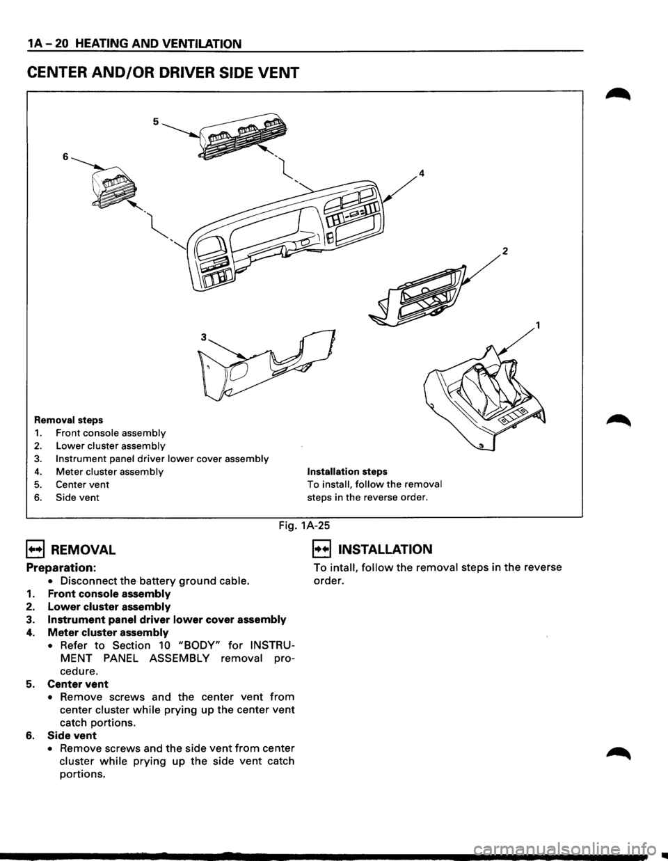
CENTER AND/OR DRIVER SIDE VENT
5
6
' -~
'
"
Removal steps
1. Front console assembly
2. Lower cluster assembly
3. Instrument panel driver lower cover assembly
4. Meter cluster assembly
5. Center vent
6. Side vent
4
Installation steps
To install, follow the removal
steps in the reverse order.
2
1
Fig. 1A-25
B REMOVAL
Preparation:
• Disconnect the battery ground cable.
1. Front console assembly
2. Lower cluster assembly
3. Instrument panel driver lower cover assembly
4. Meter cluster assembly
•
Refer to Section 10 "BODY" for INSTRU
MENT PANEL ASSEMBLY removal pro-
cedure.
5. Center vent
• Remove screws and the center vent from
center cluster while prying up the center vent
catch portions.
6. Side vent
• Remove screws and the side vent from center
cluster while prying up the side vent catch
portions.
E] INSTALLATION
To intall, follow the removal steps in the reverse
order.
..
Page 51 of 1928
HEATING AND VENTILATION 1A-21
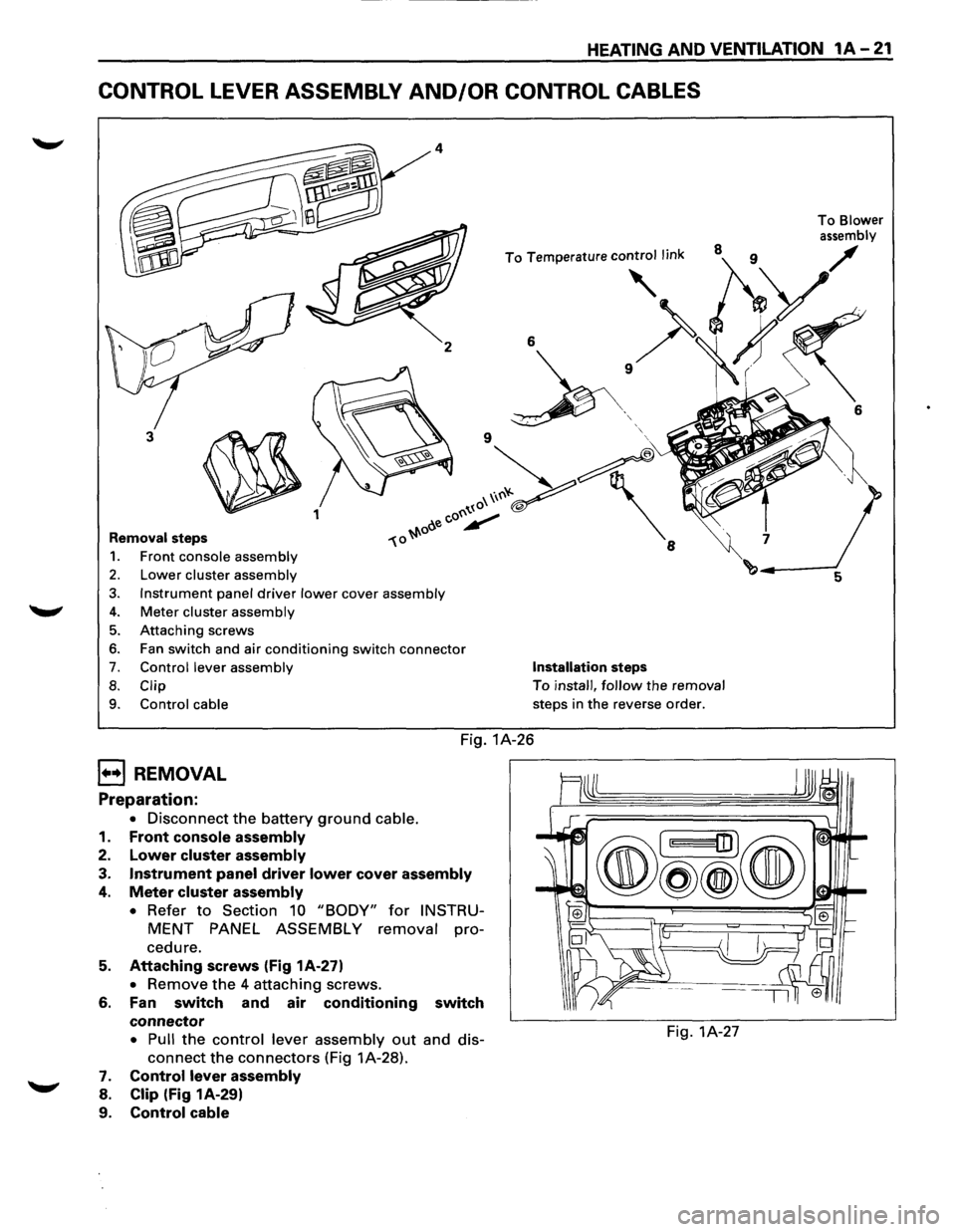
CONTROL LEVER ASSEMBLY AND/OR CONTROL CABLES
2
3
~ 1
Removal steps
1. Front console assembly
2. Lower cluster assembly
3. Instrument panel driver lower cover assembly
4. Meter cluster assembly
5. Attaching screws
6. Fan switch and air conditioning switch connector
7. Control lever assembly
8. Clip
9.
Control cable
6
' '
Installation steps
To install, follow the removal
steps in
the reverse order.
Fig. 1A-26
B REMOVAL
Preparation:
• Disconnect the battery ground cable.
1.
Front console assembly
2. Lower cluster assembly
3. Instrument panel driver lower cover assembly
4. Meter cluster assembly
• Refer to Section 10 "BODY" for INSTRU
MENT PANEL ASSEMBLY removal pro
cedure.
5. Attaching screws (Fig 1A-27)
• Remove the 4 attaching screws.
6. Fan switch and air conditioning switch
connector
• Pull the control lever assembly out and dis-
connect the connectors (Fig 1A-28).
7. Control lever assembly
8. Clip (Fig 1A-29)
9.
Control cable
Fig. 1A-27
To Blower
assembly
6
Page 52 of 1928
1A-22 HEATING AND VENTILATION
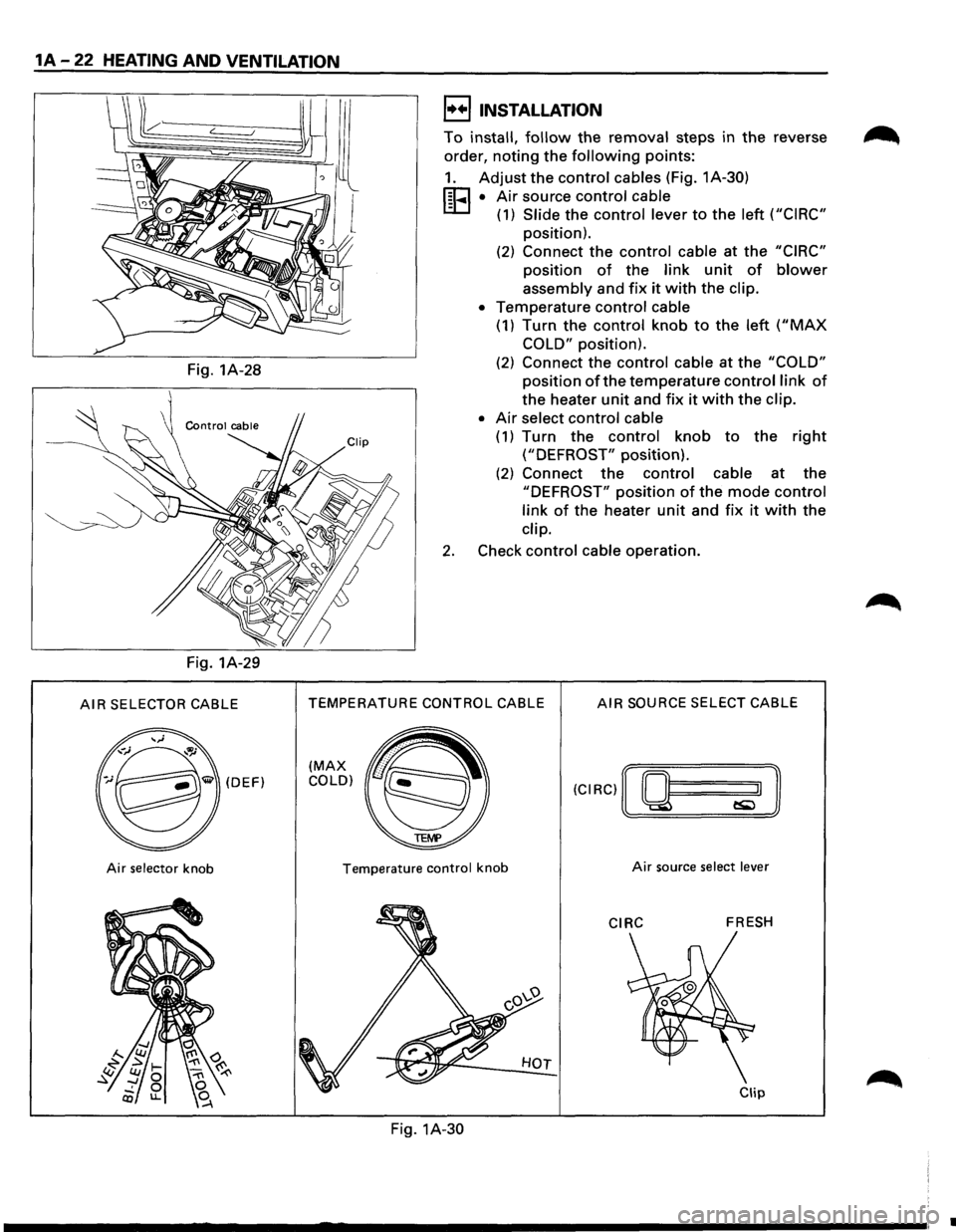
Fig. 1A-28
Fig. 1A-29
AIR SELECTOR CABLE
(DEF)
Air selector knob
I••! INSTALLATION
To install, follow the removal steps in the reverse
order,
noting the following points:
1. Adjust the control cables (Fig. 1A-30)
[E • Air source control cable
-(1) Slide the control lever to the left ("CIRC"
position).
(2)
Connect the control cable at the "CIRC"
position of the link unit of blower
assembly and fix it with the clip.
•
Temperature control cable
(1) Turn the control knob to the left ("MAX
COLD" position).
(2)
Connect the control cable at the "COLD"
position of the temperature control link of
the heater unit and fix it with the clip.
•
Air select control cable
(1) Turn the control knob to the right
("DEFROST" position).
(2) Connect the control cable at the
"DEFROST" position of the mode control
link of the heater unit and fix it with the
clip.
2. Check control cable operation.
TEMPERATURE CONTROL CABLE AIR SOURCE SELECT CABLE
(MAX COLD)
Temperature control knob
Fig. 1A-30
Air source select lever
CIRC FRESH
Clip
•
Page 53 of 1928
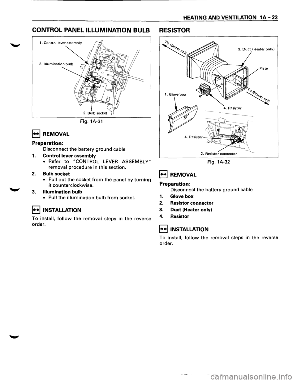
CONTROL PANEL ILLUMINATION BULB
1••1 REMOVAL
Preparation:
Fig. 1A-31
Disconnect
the battery ground cable
1. Control lever assembly
• Refer to "CONTROL LEVER ASSEMBLY"
removal
procedure in this section.
2. Bulb socket
• Pull out the socket from the panel by turning
it counterclockwise.
3.
Illumination bulb
• Pull the illumination bulb from socket.
I••IINSTALLATION
To install, follow the removal steps in the reverse
order.
HEATING AND VENTILATION 1A-23
RESISTOR
1. Glove box
1••1 REMOVAL
Preparation:
3. Duct (Heater only)
Plate
2. Resistor connector
Fig. 1A-32
Disconnect the battery
ground cable
1. Glove box
2. Resistor connector
3. Duct (Heater only)
4. Resistor
I••IINSTALLATION
To install, follow the removal steps in the reverse
order.
Page 507 of 1928
ENGINE DIAGNOSIS 6-9
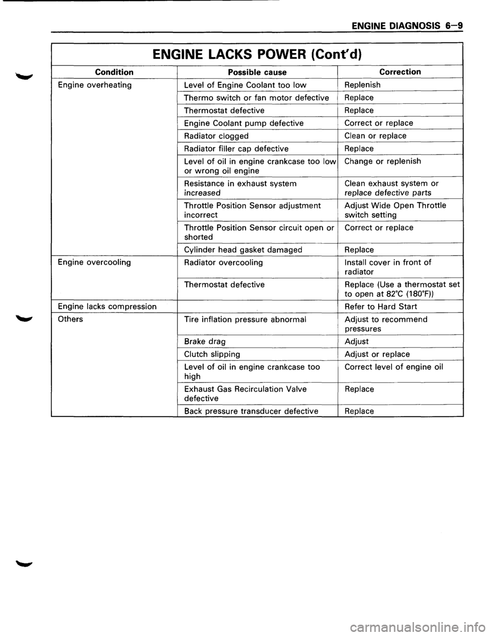
ENGINE LACKS POWER (Cont'd)
Condition Possible cause Correction
Engine overheating
Level of Engine Coolant too low Replenish
Thermo switch or fan motor defective Replace
Thermostat defective Replace
Engine
Coolant pump defective Correct or replace
Radiator clogged
Clean or replace
Radiator
filler cap defective Replace
Level
of oil in engine crankcase too low Change or replenish
or
wrong oil engine
Resistance in exhaust system
Clean exhaust system or
increased replace
defective parts
Throttle Position Sensor adjustment Adjust
Wide Open Throttle
incorrect switch setting
Throttle Position Sensor circuit open
or Correct or replace
shorted
Cylinder head gasket damaged Replace
Engine overcooling
Radiator
overcooling Install cover
in front of
radiator
Thermostat defective Replace
(Use a thermostat set
to open at a2·c (180.F))
Engine
lacks compression Refer to Hard Start
Others Tire inflation pressure
abnormal Adjust to recommend
pressures
Brake drag Adjust
Clutch slipping Adjust or replace
Level
of oil in engine crankcase too Correct level of engine oil
high
Exhaust Gas
Recirculation Valve Replace
defective
Back pressure transducer defective
Replace
Page 509 of 1928
ENGINE DIAGNOSIS 6-11
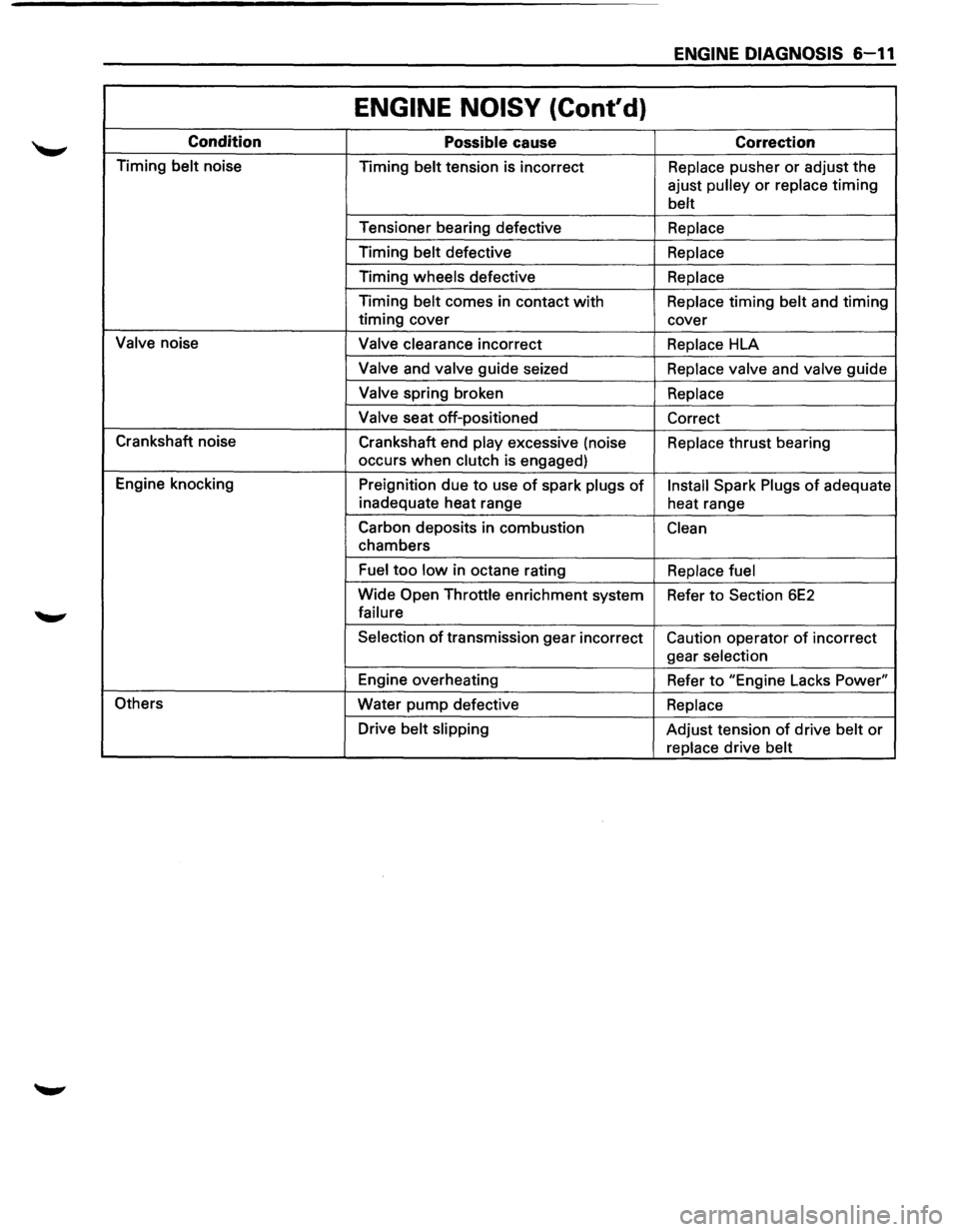
ENGINE NOISY (Cont'd)
Condition Possible cause Correction
Timing belt noise
Timing belt tension is incorrect Replace pusher or adjust the
ajust
pulley or replace timing
belt
Tensioner bearing defective Replace
Timing belt defective Replace
Timing wheels defective Replace
Timing belt comes in contact with Replace timing belt and timing
timing cover
cover
Valve noise Valve clearance incorrect Replace HLA
Valve and valve guide seized Replace valve and valve guide
Valve spring broken Replace
Valve
seat off-positioned
Correct
Crankshaft noise
Crankshaft end
play excessive (noise Replace thrust bearing
occurs
when clutch is engaged)
Engine knocking
Preignition due
to use of spark plugs of Install Spark Plugs of adequate
inadequate heat range
heat range
Carbon deposits in combustion
Clean
chambers
Fuel too low in octane rating Replace fuel
Wide Open Throttle enrichment system
Refer to Section 6E2
failure
Selection
of transmission gear incorrect Caution operator of incorrect
gear
selection
Engine overheating
Refer to "Engine Lacks Power"
Others Water
pump defective Replace
Drive belt slipping Adjust tension of drive belt or
replace drive belt
Page 546 of 1928
6A-30 GENERAL ENGINE MECHANICAL
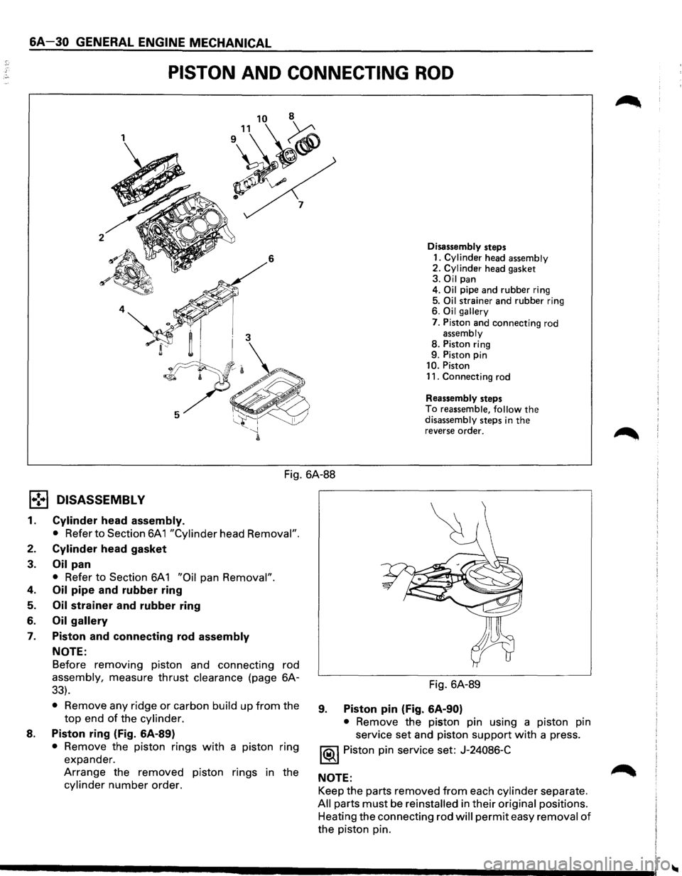
PISTON AND CONNECTING ROD
1
~~ $ 7
2 6 Disassembly
steps
1. Cylinder head assembly 2. Cylinder head gasket 3. Oil pan
4. Oil pipe and rubber ring
5. Oil strainer and rubber ring
6. Oil gallery
7. Piston and connecting rod assembly 8. Piston ring
9. Piston pin
10. Piston
11. Connecting rod
Reassembly steps
To reassemble, follow the disassembly steps in the reverse order.
Fig. 6A-88
1•! .. 1 DISASSEMBLY
1. Cylinder head assembly.
• Refer to Section 6A 1 "Cylinder head Removal".
2. Cylinder head gasket
3. Oil pan
• Refer to Section 6A1 "Oil pan Removal".
4. Oil pipe and rubber ring
5. Oil strainer and rubber ring
6. Oil gallery
7. Piston and connecting rod assembly
NOTE:
Before removing piston and connecting rod
assembly, measure thrust clearance (page 6A-
33).
• Remove any ridge or carbon build up from the
top end of the cylinder.
8. Piston ring (Fig. 6A-89)
• Remove the piston rings with a piston ring
expander.
Arrange the removed piston rings in the
cylinder number order. Fig.
6A-89
9. Piston pin (Fig. 6A-90)
• Remove the piston pin using a piston pin
service set and piston
support with a press.
1®1 Piston pin service set: J-24086-C
NOTE: Keep the parts removed
from each cylinder separate.
All parts must be reinstalled in their original positions.
Heating the connecting rod
will permit easy removal of
the piston pin.
Page 631 of 1928
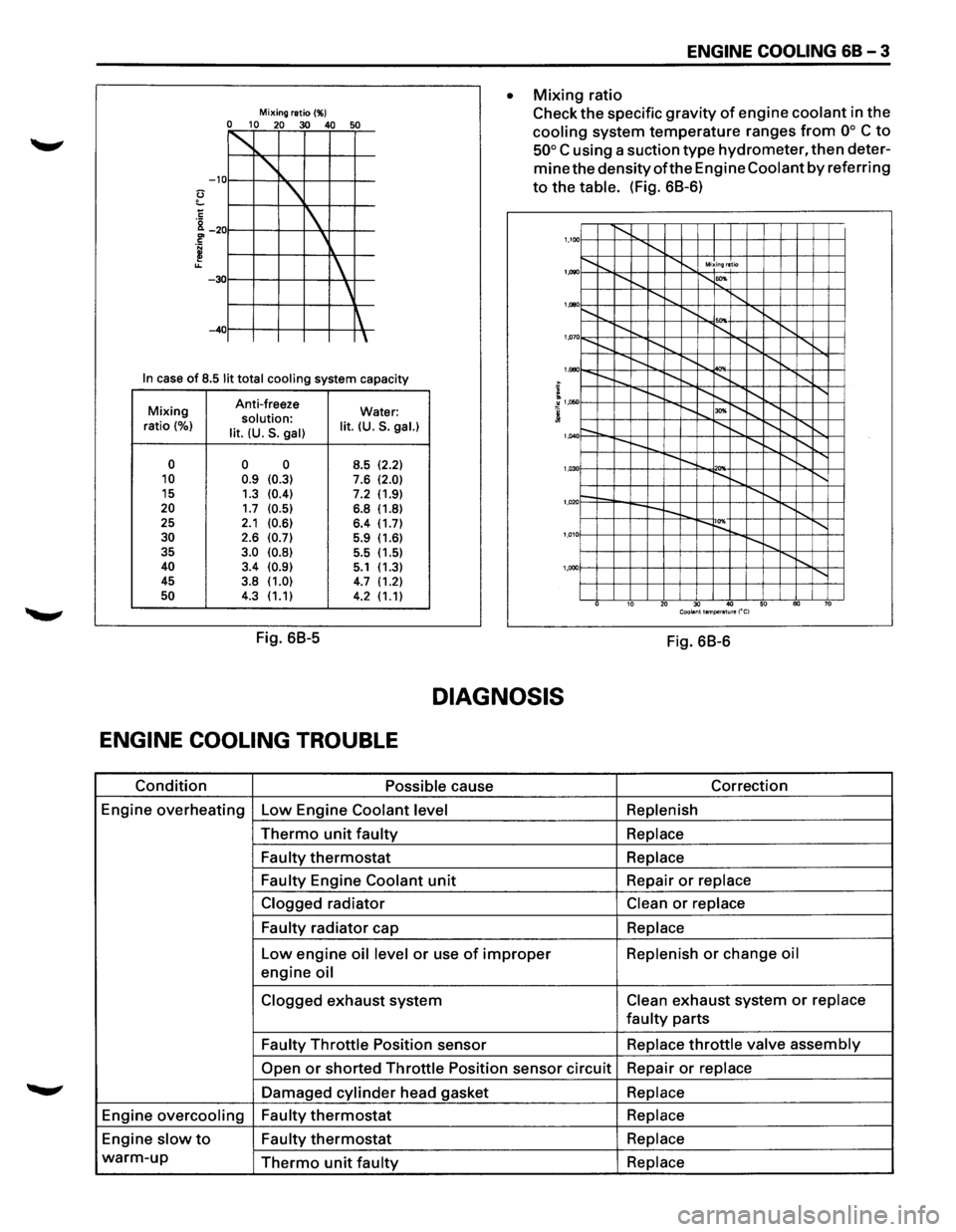
Mixing ratio(%) 0 10 20 30 40 50
~
' -10
'
1
' -30
~ -40
In case of 8.5 lit total cooling system capacity
Mixing Anti-freeze
Water: solution: ratio (%) lit. (U.S. gal) lit. (U.S. gal.)
0 0 0
8.5 (2.2) 10 0.9 (0.3) 7.6 (2.0) 15
1.3 (0.4) 7.2 (1.9) 20 1.7 (0.5) 6.8 (1.8)
25 2.1 (0.6) 6.4 (1.7) 30 2.6 (0.7) 5.9 (1.6)
35 3.0 (0.8) 5.5
(1.5) 40 3.4 (0.9) 5.1 (1.3)
45 3.8 (1.0) 4.7 (1.2) 50 4.3 (1.1)
4.2 (1.1)
Fig. 68-5
ENGINE COOLING 68-3
• Mixing ratio
Check
the specific gravity of engine coolant in the
cooling system temperature ranges from oo C to
50° C using a suction type hydrometer, then deter
mine the densityofthe Engine Coolant by referring
to the table. (Fig. 68-6)
1,100 1'-........ ........ ...... .............. Mixing ratio
~"""--r-... 1'-""' 1,1)90
........ ...... ........ ........ .......... '
1,000
'"" 1,07 o......_ 1'-........ I'-.......... I"-........ .......
I"-........ ..........
................. I"-........
'
1,080
....... I"-........ ~ ........ ......
........ "'" ~"""--r--..... 1,050
r-. ........ ~ .......... ......
---
........ ........ 1,040
r-.... !'--.. 1'-0 '"" ~"""--1'-.... ........ 1,03
1--....... ........ r--~ ........
'
1,020
....... ~ 1'-0 ~"""---.... 1,01
...... ,
'
1,000
10 20 30 40 50 60 70 Coolant temperature ("C)
Fig. 68-6
DIAGNOSIS
ENGINE COOLING TROUBLE
Condition Possible cause Correction
Engine
overheating Low Engine Coolant level Replenish
Thermo unit faulty Replace
Faulty
thermostat Replace
Faulty
Engine Coolant unit Repair or replace
Clogged
radiator Clean or replace
Faulty
radiator cap Replace
Low engine oil level or use of improper Replenish or change oil
engine oil
Clogged exhaust system Clean exhaust system or replace
faulty parts
Faulty Throttle Position sensor Replace throttle valve assembly
Open or shorted Throttle Position sensor circuit Repair or replace
Damaged cylinder head gasket Replace
Engine overcooling Faulty thermostat Replace
Engine slow to Faulty thermostat Replace
warm-up Thermo unit faulty Replace
Page 636 of 1928
'.,~-' r.
68-8 ENGINE COOLING
2. Radiator hose
• Disconnect inlet hose and outlet hose from the
engine.
3. Fan guide, lower
• Remove clips on both sides and the bottom
lock. (Fig. 68-13)
~ Cooling fan guide; lower
~
Clip
Fig. 68-13
4. Reserve tank hose
• Disconnect the hose from radiator.
5. Bracket
6. Radiator assembly
• Remove upward the radiator assembly with
hose, taking care not to damage the radiator
core
with a fan blade.
• Remove cushion rubbers on both sides at the
bottom.
~ INSPECTION
Radiator Cap
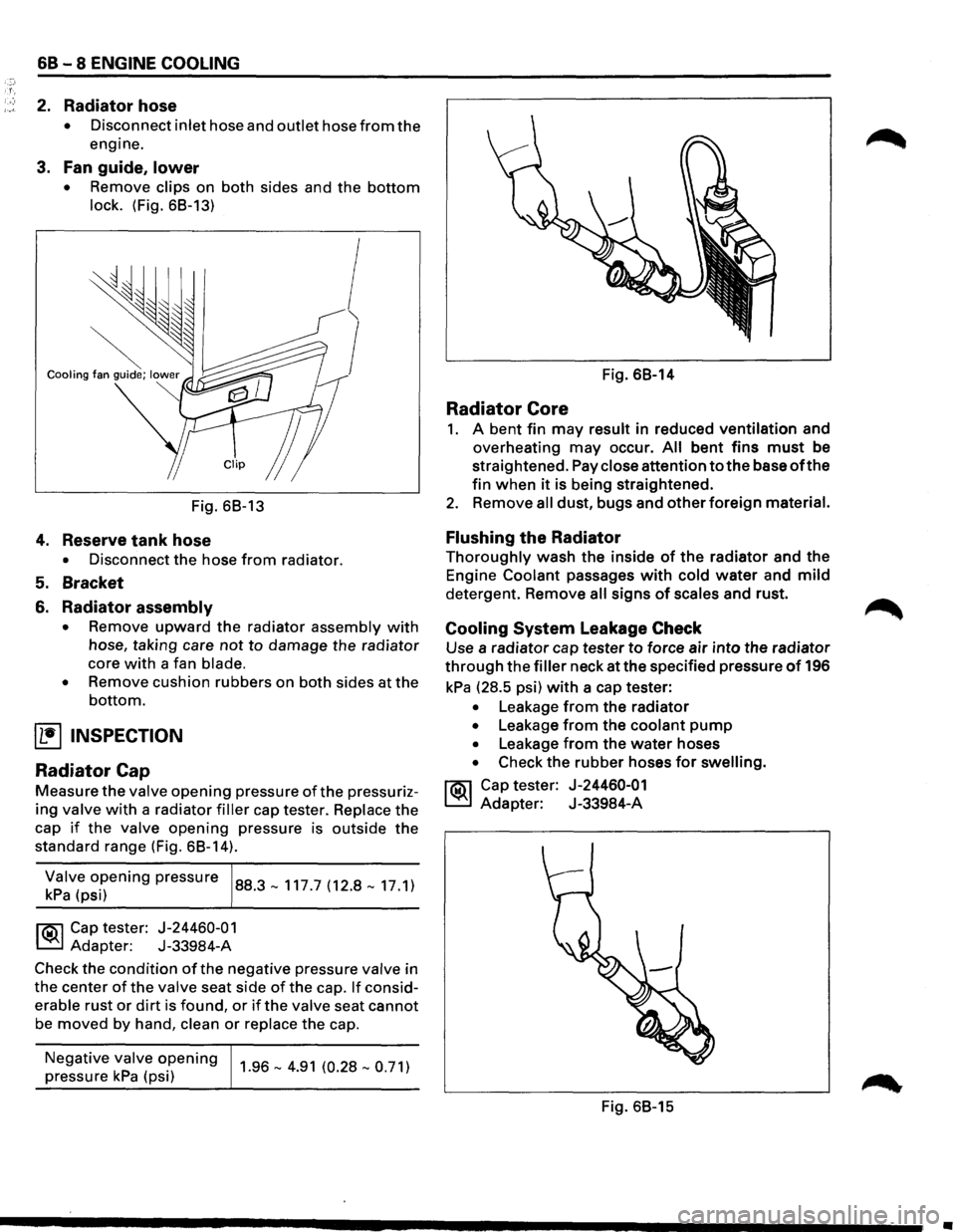
Measure the valve opening pressure of the pressuriz
ing valve with a radiator filler cap tester. Replace the
cap
if the valve opening pressure is outside the
standard range (Fig. 68-14).
~;!v(~~i~ening pressure 88.3-117.7 (12.8-17.1)
l'i':'il Cap tester: J-24460-01
~ Adapter: J-33984-A
Check the
condition of the negative pressure valve in
the center
of the valve seat side of the cap. If consid
erable rust
or dirt is found, or if the valve seat cannot
be
moved by hand, clean or replace the cap.
Negative
valve opening
pressure kPa (psi) 1.96-4.91 (0.28-0.71)
Fig. 68-14
Radiator Core
1. A bent fin may result in reduced ventilation and
overheating
may occur. All bent fins must be
straightened. Pay
close attention to the base of the
fin when it is being straightened.
2. Remove all dust, bugs and other foreign material.
Flushing the Radiator
Thoroughly wash the inside of the radiator and the
Engine
Coolant passages with cold water and mild
detergent. Remove all signs of scales and rust.
Cooling System Leakage Check
Use a radiator cap tester to force air into the radiator
through the filler neck at the specified pressure of 196
kPa (28.5 psi) with a cap tester:
• Leakage from the radiator
• Leakage from the coolant pump
• Leakage from the water hoses
• Check the rubber hoses for swelling.
rt:\1 Cap tester: J-24460-01
~ Adapter: J-33984-A
Fig. 68-15
•