heating ISUZU TROOPER 1995 Owner's Guide
[x] Cancel search | Manufacturer: ISUZU, Model Year: 1995, Model line: TROOPER, Model: ISUZU TROOPER 1995Pages: 1928
Page 788 of 1928
6E2-92 DRIVEABILITY AND EMISSIONS
LACK OF POWER, SLUGGISH OR SPONGY
Definition: Engine delivers less than expected power.
Little or no increase in speed when
accelerator
pedal is pushed down part
way.
PRELIMINARY CHECKS
• Perform the careful visual/physical checks as
described at start of "Symptoms," Section "6E2-
B."
•
Compare customer's car to similar unit. Make sure
the
vehicle has an actual problem.
• Remove air filter and check air filter for dirt, or for
being plugged. Replace as necessary.
FUEL SYSTEM
• CHECK: Rescricted fuel filter.
• CHECK: Fuel pressure, use CHART A-7.
• CHECK: Contaminated fuel.
• CHECK: Fuel injectors are correct for the vehicle.
IGNITION SYSTEM
• CHECK: Ignition timing, using "Scan tool".
• CHECK: Knock sensor system for excessive spark
retard activity. Refer to CHART
C-5. Use
"Scan tool".
• CHECK: Secondary voltage using an oscilloscope
or a spark tester J 26792 (ST-125), or
equivalent, to check for a weak coil.
ADDITIONAL CHECKS
• CHECK: Engine control module grounds for being
clean,
tight and in their proper locations.
See engine control module wiring
diagrams.
• CHECK: Exhaust gas recirculation operation for
being open or partly open all the time.
- Refer to CHART
C-7.
• CHECK: Generator output voltage. Repair if less
than 9
or more than 16 volts.
• CHECK: Exhaust system for possible restriction.
Refer
to CHART B-1.
-Inspect exhaust system for damaged
or collapsed pipes.
-
Inspect muffler for heat damage or
possible internal failure.
• CHECK: Torque converter clutch for proper
operation. Refer
to AUTOMATIC
TRANSMISSION
(SECTION 7A).
ENGINE MECHANICAL
• CHECK: Engine valve timing and compression.
• CHECK: Engine for correct or worn camshaft.
Refer
to ENGINE MECHANICAL
DIAGNOSIS
(SECTION 6A).
DETONATION/SPARK KNOCK
Definition: A mild to severe ping, usually worse under
acceleration. The engine makes sharp
metallic knocks that change with throttle
opening.
Sounds like popcorn popping.
PRELIMINARY CHECKS
• Perform the careful visual/physical checks as
Low engine coolant.
Restricted air
flow to radiator, or restricted
water flow through radiator.
Correct engine
coolant solution should be a 50/
50 mix of anti-freeze engine coolant (or
equivalent) and water.
described at start
of "Symptoms," Section "6E2-FUEL SYSTEM
B."
•
Park/Neutral position switch. Be sure "Scan tool"
indicates drive with gear selector in drive or
overdrive. Use
CHART C-1A.
• If "Scan tool" readings are normal (see facing page
of on-board diagnostic system check) and there
are no engine mechanical faults,
fill fuel tank with a
gasoline
that has a minimum octane reading of 87
and revaluate vehicle performance.
• CHECK: Exhaust gas recirculation system for not
opening. Use CHART C-7.
COOLING SYSTEM
• Check for obvious overheating problems:
• NOTICE: To determine if the condition is caused by
a rich
or lean system, the car should be
driven at the speed
of the complaint.
Monitoring
LT. Fuel Trim will help
identify problem.
Lean-
LT. Fuel Trim above 142. Refer to
"Diagnostic Aids" on facing page of
diagnostic trouble code 44.
Rich-LT. Fuel Trim below 118. Refer to
"Diagnostic Aids" on facing page of
diagnostic trouble code 45.
• CHECK: Fuel pressure, use CHART A-7.
..
Page 797 of 1928
will not light when connected to the circuit. In some
cases, even an ordinary shop voltmeter
will not give an
accurate reading because its resistance is
too low.
Therefore, a 10 megohms input impedance digital
voltmeter is required to assure accurate voltage
readings.
The Engine
Control Module (ECM) controls output
circuits such as the fuel injectors, idle air control valve,
air conditioning clutch relay, etc. by controlling the
ground circuit through transistors
or a device called a
"quad-driver".
INFORMATION SENSORS
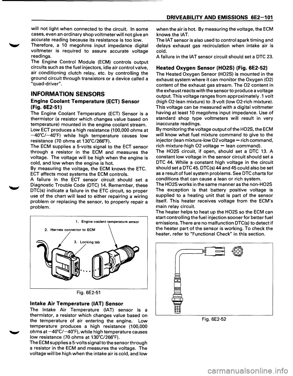
Engine Coolant Temperature (ECT) Sensor
(Fig. 6E2-51)
The Engine Coolant Temperature (ECT) Sensor is a
thermistor
(a resistor which changes value based on
temperature) mounted in the engine coolant stream.
Low ECT produces a high resistance (1 00,000 ohms at
-40.C/-40.F) while high temperature causes low
resistance (70 ohms at 130.C/266.F).
The ECM supplies a 5-volts signal to the ECT sensor
through a resistor in the
ECM and measures the
voltage. The voltage
will be high when the engine is
cold, and low when the engine is hot.
By measuring the voltage, the
ECM knows the ETC.
ECT affects most systems the ECM controls.
A failure in the
ECT sensor circuit should set a
Diagnostic Trouble Code
(DTC) 14. Remember, these
DTC(s) indicate a failure in the
ETC circuit, so proper
use
of the chart will lead to either repairing a wiring
problem or replacing the sensor, to properly repair a
problem.
1. Engine coolant temperature sensor
2. Harness connector to ECM
3. Locking tab
Fig. 6E2-51
Intake Air Temperature (IAT) Sensor
The Intake Air Temperature (IAT) sensor is a
thermistor, a resistor which changes
value based on
the temperature
of air entering the engine. Low
temperature produces a high resistance
(1 00,000
ohms at -4o·c/-40.F), while high temperature causes
low resistance (70 ohms at 130.C/266.F).
The ECM supplies a 5-volts signal to the sensor through
a resistor in the
ECM and measures the voltage. The
voltage
will be high when the intake air is cold, and low
DRIVEABILITV AND EMISSIONS 6E2-1 01
when the air is hot. By measuring the voltage, the ECM
knows the lAT.
The IAT sensor is also used to control spark timing and
delays exhaust gas recirculation when intake air is
cold.
A failure in the IAT sensor circuit should set a DTC 23.
Heated Oxygen Sensor (H02S) (Fig. 6E2-52)
The Heated Oxygen Sensor (H02S) is mounted in the
exhaust system where
it can monitor the Oxygen (02)
content of the exhaust gas stream. The 02 content in
the exhaust reacts
with the sensor to produce a voltage
output. This voltage ranges
from approximately .1 volt
(high 02-lean mixture) to .9 volt (low 02-rich mixture).
This voltage can
be measured with a digital voltmeter
having at
least 10 megohms input impedance. Use of
standard shop type voltmeters will result in very
inaccurate readings.
By monitoring the voltage
output ofthe H02S, the ECM
will know what fuel mixture command to give to the
injector
(lean mixture-low 02 voltage= rich command,
rich mixture-high
02 voltage= lean command).
The
H02S circuit, if open, should set a DTC 13. A
constant
low voltage in the sensor circuit should set a
DTC 44. While a constant high voltage in the circuit
should set a DTC 45. DTC(s) 44 and 45 could also be set
as a result of fuel system problems. See DTC charts for
conditions that can cause a lean or rich system.
The
H02S works in the same manner as the non-H02S
The exception is that battery positive voltage is
supplied to a heating unit that is part of the sensor
itself. This heater receives voltage
from the ECM's
main
relay circuit.
The heater
helps to heat up the H02S so the ECM can
start
controlling the fuel injection sooner for better fuel
emissions. There are no malfunction DTC(s) to detect if
the heater part of the sensor is working. To check the
heater, refer to "Functional
Check" in this section.
Fig. 6E2-52
~
\W
Page 858 of 1928
6E2-162 DRIVEABILITY AND EMISSIONS
CHART C-10
AIR CONDITIONING (A/C) SYSTEM FUNCTIONAL CHECK
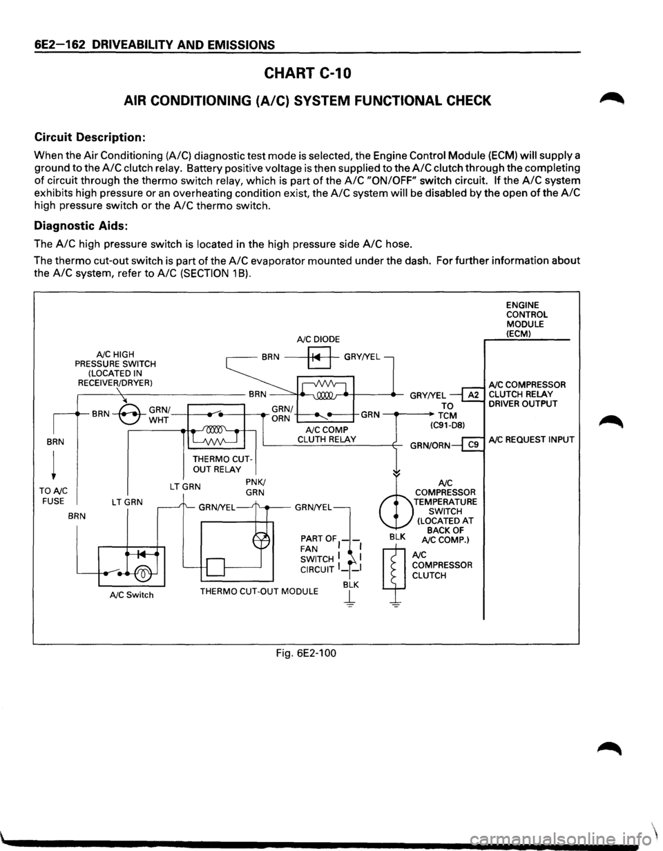
Circuit Description:
When the Air Conditioning (A/C) diagnostic test mode is selected, the Engine Control Module (ECM) will supply a
ground to the
A/C clutch relay. Battery positive voltage is then supplied to the A/C clutch through the completing
of circuit through the thermo switch relay, which is part of the A/C "ON/OFF" switch circuit. If the A/C system
exhibits high pressure or
an overheating condition exist, the A/C system will be disabled by the open of the A/C
high pressure switch or the A/C thermo switch.
Diagnostic Aids:
The A/C high pressure switch is located in the high pressure side A/C hose.
The
thermo cut-out switch is part of the A/C evaporator mounted under the dash. For further information about
the
A/C system, refer to A/C (SECTION 1 8).
BRN
TONC FUSE
NC HIGH
PRESSURE SWITCH
(LOCATED IN
RECEIVER/DRYER)
LTGRN
BRN
NC Switch
NC DIODE
BRN a GRY!YEL
THERMO CUTOUT RELAY
LTGRN PNK/ GRN
NCCOMP CLUTH RELAY
PARTOF1-FAN I SWITCH I I CIRCUIT I __ I
BLK THERMO CUT-OUT MODULE j_
Fig. 6E2-100
ENGINE
CONTROL
MODULE (ECM)
NC COMPRESSOR CLUTCH RELAY DRIVER OUTPUT
NC REQUEST INPUT
Page 863 of 1928
ENGINE EXHAUST (V6 3.2L) 6F-1
SECTION 6F
ENGINE EXHAUST (V6 3.2L)
\fl CAUTION:
VI Exhaust system components must have enough clearance from the upderbody to prevent overheating the
floor pan and damaging the passenger compartment, insulation
and trim materials.
CONTENTS
General Description . . . . . . . . . . . . . . . . . . . . 6F,....1
Hangers ........................... , ... ..-6f-2
Three Way Catalytic Converter ....• ·; ~. 6F-2
Gasket . . . . . . . . . . . . . . . . . . . . . . . . . . . . . 6F-2
On-Vehicle Service ........ , . . . . . . . . . . . 6F-3
Front Exhaust Pipe ... , " ;< . . . . . . . . . . . . 6F-3
Center Exhaust Pipe.. .. : -. . . . . . . . . . . . . . . . 6F-4
.. .r·
Three Way Catalytic Converter . . . . . . . . . 6F-5
Pre Catalytic Converter . . . . . . . . . . . . . . . 6F-6
Exhaust Silencer . . . . . . . . . . . . . . . . . . . . . 6F-7
Rear Exhaust Pipe . . . . . . . . . . . . . . . . . . . . 6F-8
Exhaust Pipe Mounting Rubber . . . . . . . . 6F-9
Main Data and Specifications ........... 6F-10
Torque Specifications ............... 6F-10
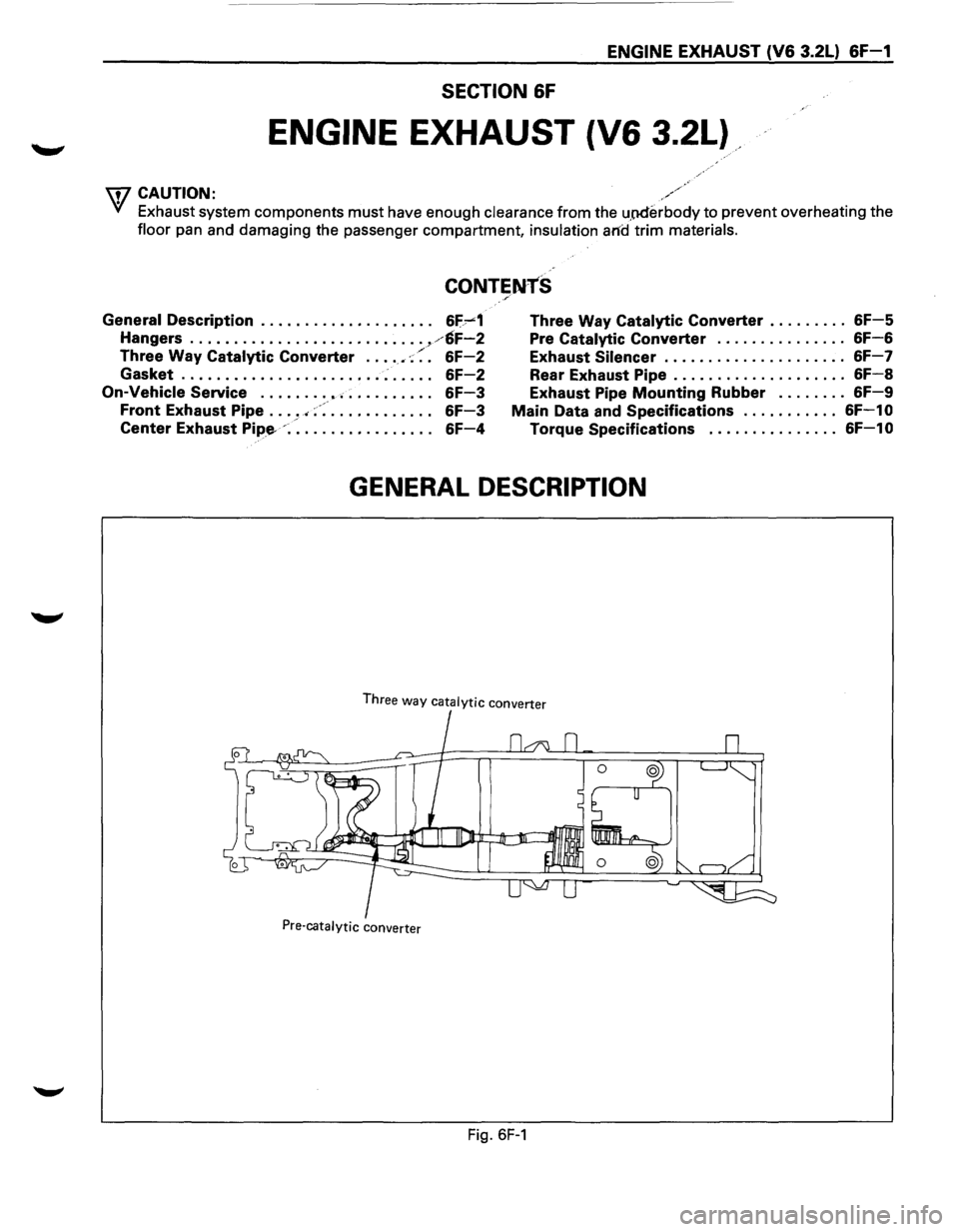
GENERAL DESCRIPTION
Three way catalytic converter
Pre-catalytic converter
Fig. 6F-1
Page 864 of 1928
6F-2 ENGINE EXHAUST (V6 3.2L)
When inspecting or replacing exhaust system
components, make sure there is adequate
clearance
from all points on the underbody to prevent over
heating the
floor pan and possible damage to the
passenger
compartment insulation and trim materials.
Check complete exhaust system and nearby body
areas and rear compartment lid for broken, damaged,
missing
or mispositioned parts, open seams, holes,
loose
connections or other deterioration which could
permit exhaust fumes to seep into the rear
compartment or passenger compartment. Dust or
water in the rear compartment may be an indication of
a problem in one of these areas. Any faulty areas
should be corrected immediately.
HANGERS
Various types of hangers are used to support exhaust
system(s). These
include conventional rubber straps,
rubber rings, and rubber
blocks.
The installation of exhaust system supports is very
important,
as improperly installed supports can cause
annoying vibrations
which can be difficult to diagnose.
THREE WAY CATAL VTIC CONVERTER
The three way catalytic converter is an emission
control device added to the exhaust system to reduce
pollutants from the exhaust gas stream.
W CAUTION:
VI • The catalytic converter requires the use of
unleaded fuel only.
Periodic
maintenance of the exhaust system is not
required. If the vehicle is raised for other service, it is
advisable to check the condition of the complete
exhaust system.
A
dual bed monolith catalytic converter is used in
combination
with three way catalytic converter.
Catalytic Types:
Three
way (Reduction/Oxidation) catalyst
The catalyst coating on the three way (reduction)
converter contains
platinum and rhodium which
lowers the levels of oxide of nitrogen (NOx) as well as
hydrocarbons (HC) and carbon monoxide (Co).
GASKET
The gasket must be replaced whenever a new exhaust
pipe,
muffler or catalytic converter is installed.
Page 1458 of 1928
8-268 CHASSIS ELECTRICAL
l~t'
B-55 No.
Operating
ina
I 10 5 1 8 direction
Ho. 7
c±l e Left
e c±l Right
Right
e c±l Up
c±l e Down
c±l e Left
Left
e c±l Right
e c±l Up
<±> e Down
Fig. 8-312
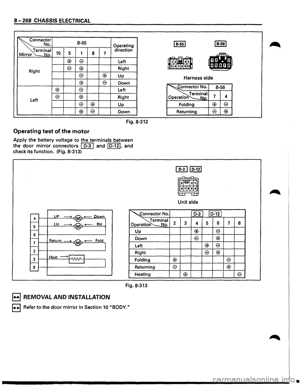
Operating test of the motor
Apply the battery voltage to the terminals between
the
door mirror connectors ~ and ID-121, and
check its function. (Fig. 8-313)
I B-ssl I B-561
•
• ,...., s.:::L -=--
~it! I]&ISI7111t11ol:l 8
Harness side
~nnector No. B-56
~erminal Ope rat o Nn. 7 4
Folding <±> e
Returning e <±>
~ ID-121
_.....,_ .r-1
m 4
~ L..U.
Unit side
......--UP -oown ~onnector No . I D-31 I D-121
--M 4 ~~nal 1--LH RH Opera .,No. 2 3 4 5 6 7 5 --M -1---Up <±> e 6 e <±> -Return--Fold Down 7 M --I Left <±> e
2 Right e <±> -Heat --1 .AAA I 3 I v v I Folding c±l e -8 Returning e c±l L...-Heating <±>
Fig. 8-313
EJ REMOVAl AND INSTAllATION
1++1 Refer to the door mirror in Section 10 "BODY."
8
e
•
Page 1786 of 1928
10-28 BODY
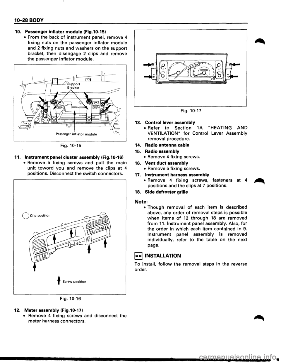
10. Passenger inflator module (Fig.10-15)
• From the back of instrument panel, remove 4
fixing nuts on the passenger inflator module
and 2 fixing nuts and washers on the support
bracket, then disengage 2 clips and remove
the passenger
inflator module.
Passenger inflator module
Fig. 10-15
11. Instrument panel cluster assembly (Fig.10-16)
• Remove . 5 fixing screws and pull the main
unit toward you and remove the clips at 4
positions. Disconnect the switch connectors.
,.-, I ) Clip position --~
t Screw position
Fig. 10-16
12. Meter assembly (Fig.10-17)
• Remove 4 fixing screws and disconnect the
meter harness connectors. Fig.
10-17
13. Control lever
assembly
• Refer to Section 1A "HEATING AND
VENTILATION" for Control Lever Assembly
removal procedure.
14. Radio antenna cable
15. Radio assembly
• Remove 4 fixing screws.
16.
Vent duct assembly
• Remove 5 fixing screws.
17.
Instrument harness assembly
• Remove 4 fixing screws, fasteners at 4 ~
positions and the clips at 7 positions.
18.
Side defroster grille
Note:
• Though removal of each item is described
above, any
order of removal steps is possible
when items of 12 through 18 are removed
from 11. Instrument panel assembly. Also, for
the order in which each item contained in 9.
Instrument panel assembly is removed
individually, refer to the table on the next
page.
I+•IINSTALLATION
To install, follow the removal steps in the reverse
order.
II