instrument cluster ISUZU TROOPER 1995 Owner's Manual
[x] Cancel search | Manufacturer: ISUZU, Model Year: 1995, Model line: TROOPER, Model: ISUZU TROOPER 1995Pages: 1928
Page 1508 of 1928
8-318 CHASSIS ELECTRICAL
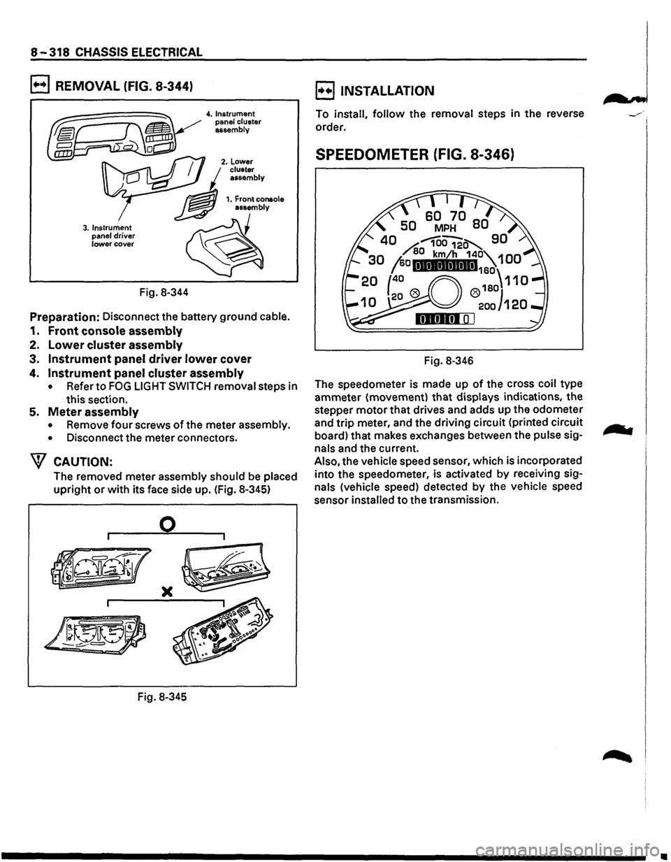
B REMOVAL (FIG. 8-344)
3. Instrument
panel driver lower cover
Fig. 8-344
4. Instrument
panel cluster
assembly
Preparation: Disconnect the battery ground cable.
1. Front console assembly
2. Lower cluster assembly
3. Instrument panel driver lower cover
4. Instrument panel cluster assembly
• Refer to FOG LIGHT SWITCH removal steps in
this section.
5. Meter assembly
• Remove four screws of the meter assembly.
•
Disconnect the meter connectors.
W CAUTION:
The removed meter assembly should be placed
upright or with its face side up. (Fig. 8-345)
0
)(
Fig. 8-345
B INSTALLATION
To install, follow the removal steps in the reverse
order.
SPEEDOMETER (FIG. 8-346)
Fig. 8-346
The speedometer is made up
of the cross coil type
ammeter (movement)
that displays indications, the
stepper
motor that drives and adds up the odometer
and
trip meter, and the driving circuit (printed circuit
board) that makes exchanges between the
pulse sig
nals and the current.
Also, the vehicle speed sensor, which is incorporated
into the speedometer, is activated
by receiving sig
nals (vehicle speed) detected by the vehicle speed
sensor
installed to the transmission.
•
Page 1614 of 1928
9B-30 CRUISE CONTROL
1. Front console assembly
• Remove four screws.
• Remove the transmission shift lever knob.
• Remove the transfer shift lever knob.
• Disconnect the seat heater switch connectors
(If so equipped).
• Disconnect the "POWER & WINTER" switch
connectors (A/T only).
2. Lower cluster assembly
• Remove three screws.
• Disconnect the cigar lighter connectors.
• Remove the cigar lighter illumination bulb
socket.
• Disconnect the ashtray illumination bulb
connector.
3. Instrument panel driver lower cover
• Remove the engine hood opener.
• Remove three screws and clip.
•
Disconnect four fasteners.
4. Steering cowl
• Remove seven screws.
5. Starter switch
• Disconnect the connector.
• Remove the screw.
8 INSTALLATION
To install, follow the removal steps in the reverse
order noting the following point.
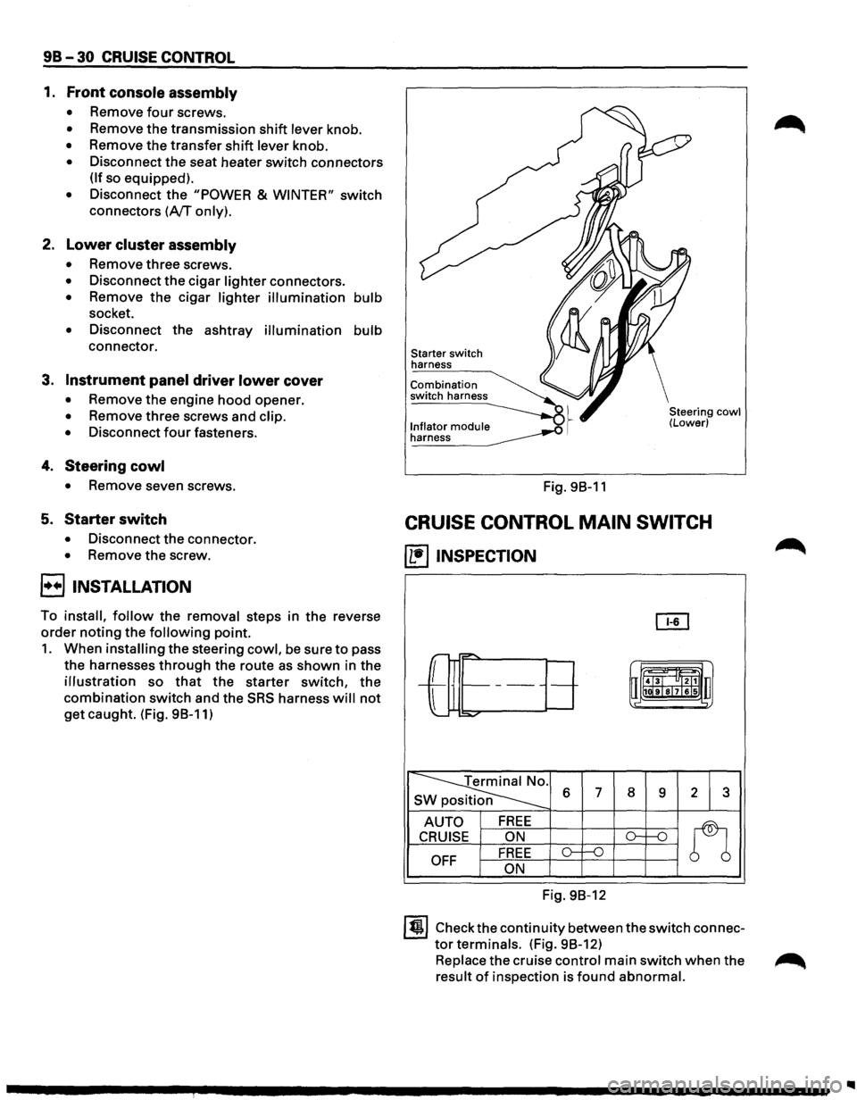
1. When installing the steering cowl, be sure to pass
the harnesses
through the route as shown in the
illustration so that the starter switch, the
combination switch and the SRS harness will not
get caught. (Fig. 98-11)
Starter switch
harness
Combination
switch harness
l._n!~~~o!_ module __..o .~ ~
Fig. 98-11
Steering cowl (Lower)
CRUISE CONTROL MAIN SWITCH
(1!1 INSPECTION
OI1
r-="'
-L
r= t-------uii4J~l "ltl1 u
l
1111ilr9Tsl7lels .,
:::o.,..o-
~ s 6 7 8 9 2 3
AUTO FREE
n
CRUISE ON ()-1---n
OFF FREE o-f--0
ON
Fig. 98-12
ltjl Check the continuity between the switch connec
tor terminals. (Fig. 98-12)
Replace the cruise control main switch when the ~
result of inspection is found abnormal.
Page 1615 of 1928
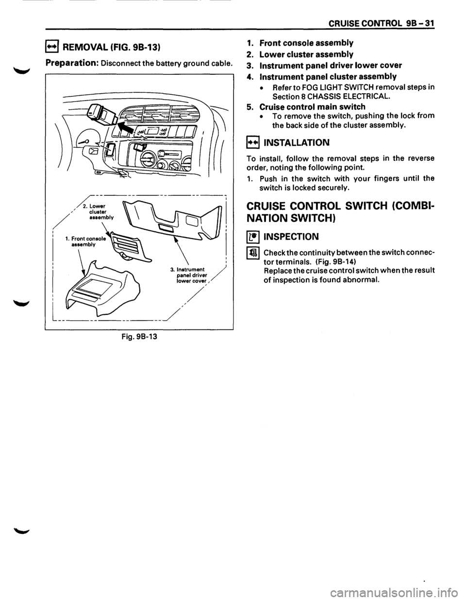
B REMOVAL (FIG. 98-13)
Preparation: Disconnect the battery ground cable.
Fig.
98-13
CRUISE CONTROL 98-31
1. Front console assembly
2. Lower cluster assembly
3. Instrument panel driver lower cover
4. Instrument panel cluster assembly
• Refer to FOG LIGHT SWITCH removal steps in
Section 8 CHASSIS ELECTRICAL.
5. Cruise control main switch
• To remove the switch, pushing the lock from
the back side of the cluster assembly.
B INSTALLATION
To install, follow the removal steps in the reverse
order, noting the
following point.
1. Push in the switch with your fingers until the
switch is locked securely.
CRUISE CONTROL SWITCH (COMBI
NATION SWITCH)
(b!] INSPECTION
I till Check the continuity between the switch connec
tor terminals. (Fig. 98-14)
Replace the cruise control switch when the result
of inspection is found abnormal.
Page 1618 of 1928
98-34 CRUISE CONTROL
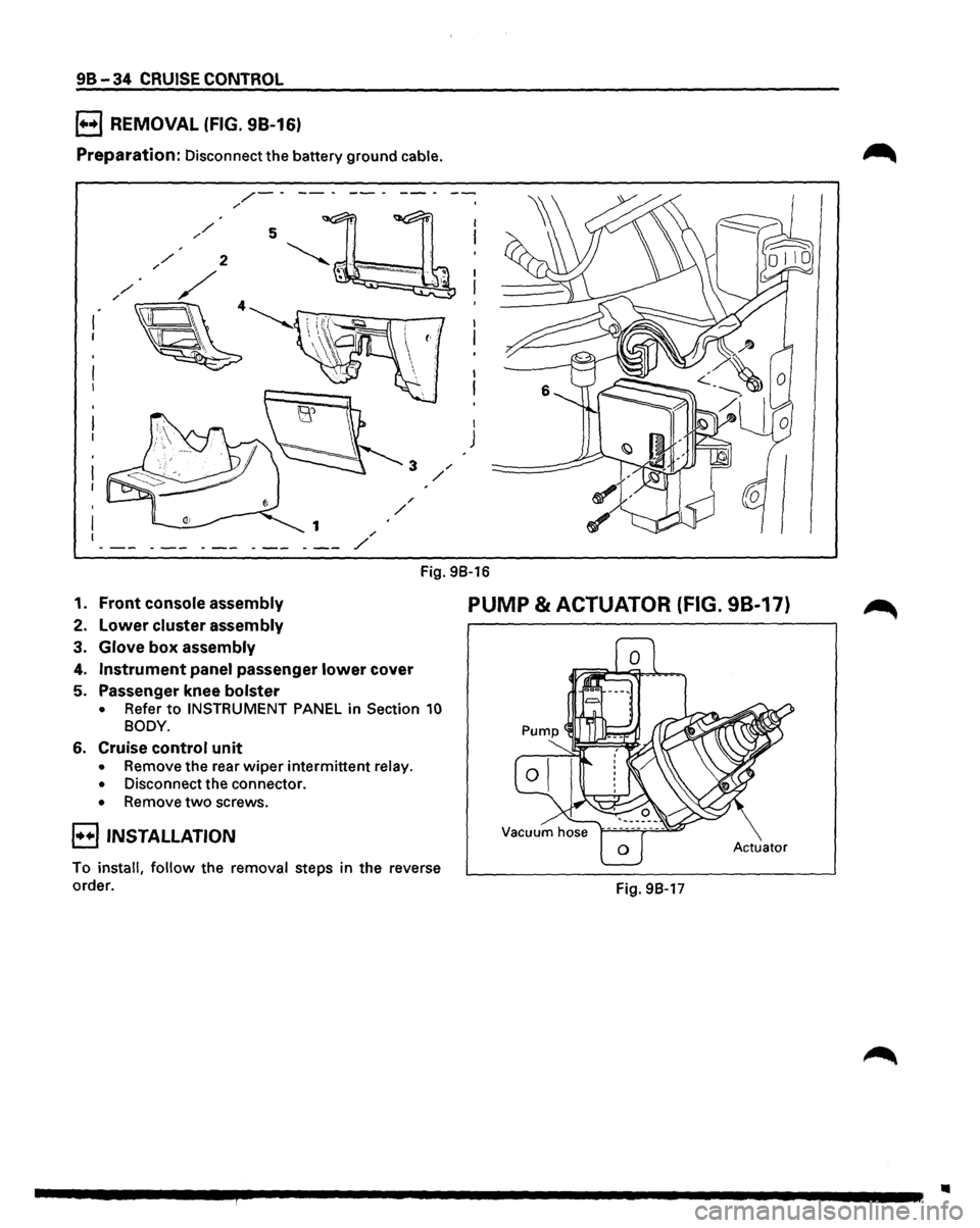
B REMOVAL (FIG. 98-16)
Preparation: Disconnect the battery ground cable.
/-----/
I
J
Fig. 98-16
1. Front console assembly
2. Lower cluster assembly
3. Glove box assembly
4. Instrument panel passenger lower cover
5. Passenger knee bolster
• Refer to INSTRUMENT PANEL in Section 10
BODY.
6. Cruise control unit
• Remove the rear wiper intermittent relay.
• Disconnect the connector.
• Remove two screws.
E) INSTALLATION
To install, follow the removal steps in the reverse
order.
PUMP & ACTUATOR (FIG. 98-17)
Actuator
Fig. 98-17
..
Page 1662 of 1928
9J-38-~tal Restraint System
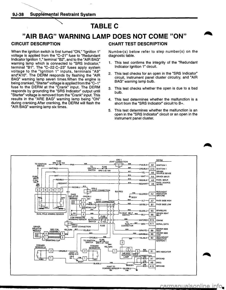
TABLE C
"AIR BAG" WARNING LAMP DOES NOT COME "ON"
CIRCUIT DESCRIPTION
When the ignition switch is first turned "ON," "Ignition 1"
voltage is applied from the "C-21" fuse to "Redundant
Indicator Ignition 1 ,"terminal "B2", and to the "AIR BAG"
warning lamp which is connected to "SRS Indicator,"
terminal "B1".
The "C-22·C-23" fuses apply system
voltage to the "Ignition 1" inputs, terminals "A9"
and"A10". The DERM responds by flashing the "AIR
BAG"
warning lamp seven times.When the engine is
being cranked,
"Starter'' voltage is applied from the "C-1"
fuse to the DERM at the "Crank" input. The DERM
responds by grounding the
"SRS Indicator'' output until
"Starter" voltage
is removed from the "Crank" input. This
results in the "ARE BAG" warning lamp being "ON"
during cranking.After cranking, the DERM will flash the
"AIR BAG" warning lamp six times.
TO IGNITION
SWITCH
FUSEj
SRS C-24 10A-
1Bot RD
FUSE SRS C-23 10A ,. ..
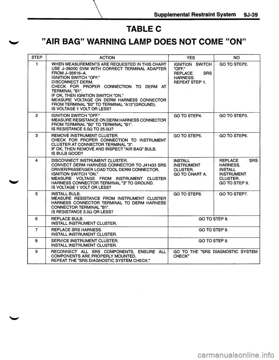
CHART TEST DESCRIPTION
Number(s) below refer to step number(s) on the
diagnostic table.
1. This test confirms the integrity of the "Redundant
Indicator Ignition 1" circuit.
2. This test checks for an open in the "SRS Indicator"
circuit, instrument panel cluster circuitry, and "AIR
BAG"
warning lamp bulb.
3. This test checks whether the open is due to a bad
bulb.
4. This test determines whether the malfunction is a
short from the
"SRS Indicator'' circuit to B+.
5. This test determines whether the malfunction is an
open in the "SRS Indicator'' circuit or an open in the
instrument
panel cluster.
SRS-1 JOINT CONNECTION
1834
IGNITION 1 IGNITION 1 DRIVER SOURCE SENSE DRIVER 36VLR PASS. 36VLR
REDUNDAT
INDICATOR GROUND
PASS
SIDE HIGH
PASS
SIDE LOW
1---''""""'-------'l-----l--'1-~--'TO ~&'Jc~ELT 1833 BLU FUSE N-7-ST.,AR_TE.,_R+-'l---'1----"''"'"'-"---WHT/RED C-1 0A Al'6L ____.Jill_ BAN FUSE CONNECTOR 1819
1820
SERIAL DATA
DRIVER SIDE HIGH DRIVER SIDE LOW REDUNDANT INDICATOR
IGNITION 1
SRS INDICA TOR
•
Page 1663 of 1928
Supplemental Restraint System 9J-39
TABLE C
._, "AIR BAG" WARNING LAMP DOES NOT COME "ON"
STEP
ACTION YES NO
1
WHEN MEASUREMENTS ARE REQUESTED IN THIS CHART IGNITION SWITCH GOTOSTEP2. USE J-39200 DVM
WITH CORRECT TERMINAL ADAPTER "OFF."
FROM J-35616-A. REPLACE SRS
IGNITION SWITCH "OFF."
HARNESS.
DISCONNECT
DERM. REPEAT STEP 1. CHECK FOR PROPER CONNECTION TO DERM AT TERMINAL "B1 ".
IF OK, THEN IGNITION SWITCH "ON." MEASURE VOLTAGE ON DERM HARNESS CONNECTOR
FROM TERMINAL "B2" TO TERMINAL "A12"(GROUND).
IS VOLTAGE
1 VOLT OR LESS?
2 IGNITION SWITCH "OFF." GOTOSTEP4. GOTO STEP3.
MEASURE RESISTANCE ON DERM HARNESS CONNECTOR
FROM TERMINAL "B2" TO TERMINAL "B1".
IS RESISTANCE
5.0.Q TO 25.0.Q?
3 REMOVE INSTRUMENT CLUSTER. GOTOSTEP5. GOTOSTEP6. CHECK FOR PROPER CONNECTION TO
INSTRUMENT
CLUSTER AT CONNECTOR TERMINAL "3".
IF OK, THEN REMOVE AND INSPECT "AIR BAG" BULB. IS BULB GOOD?
4 DISCONNECT INSTRUMENT CLUSTER.
INSTALL REPLACE SRS
CONNECT DERM HARNESS CONNECTOR TO J41433 SRS
INSTRUMENT HARNESS.
DRIVER/PASSENGER LOAD TOOL
DERM CONNECTOR.
CLUSTER. INSTALL
IGNITION SWITCH "ON."
GO TO
CHART A. INSTRUMENT
MEASURE VOLTAGE FROM INSTRUMENT
CLUSTER CLUSTER.
HARNESS CONNECTOR TERMINAL "3" TO
GROUND. GOTOSTEP9. IS VOLTAGE 1 VOLT OR LESS?
5 INSTALL BULB. GOTO STEPS. GO
TO STEP?.
MEASURE RESISTANCE FROM INSTRUMENT CLUSTER
HARNESS CONNECTOR TERMINAL TO
DERM HARNESS
CONNECTOR TERMINAL "B1".
IS RESISTANCE 5.0n OR LESS?
6 REPLACE BULB. GOTOSTEP9. INSTALL INSTRUMENT CLUSTER.
7 REPLACE SRS HARNESS. GOTOSTEP9. INSTALL INSTRUMENT CLUSTER.
8 SERVICE INSTRUMENT CLUSTER. GOTOSTEP9. INSTALL INSTRUMENT CLUSTER.
9
RECONNECT ALL SRS COMPONENTS, ENSURE ALL GO TO THE "SRS DIAGNOSTIC SYSTEM
COMPONENTS ARE PROPERLY MOUNTED. CHECK" REPEAT THE "SRS DIAGNOSTIC SYSTEM CHECK."
Page 1746 of 1928
9J-122 Supplemental Restraint System
DUAL POLE ARMING SENSOR
WARNING: DURING SERVICE PROCEDURES, BE VERY CAREFUL WHEN HANDLING A SENSOR. NEVER ~
STRIKE OR JAR A SENSOR. UNDER SOME CIRCUMSTANCES, IT COULD CAUSE DEPLOYMENT AND
RESULT IN PERSONAL INJURY OR IMPROPER OPERATION OF THE SUPPLEMENTAL RESTRAINT SYSTEM(
SRS
). ALL SENSOR AND MOUNTING BRACKET BOLTS MUST BE CAREFULLY TORQUED TO ASSURE
PROPER OPERATION. NEVER POWER
UP THE SRS WHEN ANY SENSOR IS NOT RIGIDLY ATTACHED TO
VEHICLE, SINCE
THE SENSOR COULD BE ACTIVATED WHEN NOT ATTACHED AND COULD RESULT IN
DEPLOYMENT.
WARNING: PROPER OPERATION OF THE SENSORS AND SUPPLEMENTAL RESTRAINT SYSTEM( SRS)
REQUIRES
THAT ANY REPAIRS TO THE VEHICLE STRUCTURE RETURN IT TO ITS ORIGINAL PRODUCTION
CONFIGURATION.
DEPLOYMENT (CURRENT CODE 51 )OR ANY VISIBLE DAMAGE TO SENSOR AND/OR
THEIR MOUNTING
BRACKETS REQUIRES REPLACEMENT, NOT REPAIR. PROPER OPERATION OF A
SENSOR ALSO REQUIRES THAT SENSOR BE RIGIDLY BOLTED TO THE VEHICLE STRUCTURE. THE ARROW
ON
THE SENSOR MUST BE POINTING TOWARD THE FRONT OF THE VEHICLE. FAILURE TO OBSERVE
THESE PRECAUTIONS CAN RESULT IN IMPROPER SRS OPERATION AND POSSIBLE LACK OF
SUPPLEMENTAL RESTRAINT PROTECTION FOR THE DRIVER AND PASSENGER DURING AN ACCIDENT
IMPACT.
All
sensors are specifically calibrated and are keyed to the sensor location and SRS wiring harness. Caution should
be used to ensure proper location of the sensors. The keying of the sensor to their locations and wiring harness
connectors should never be modified
in the filed.
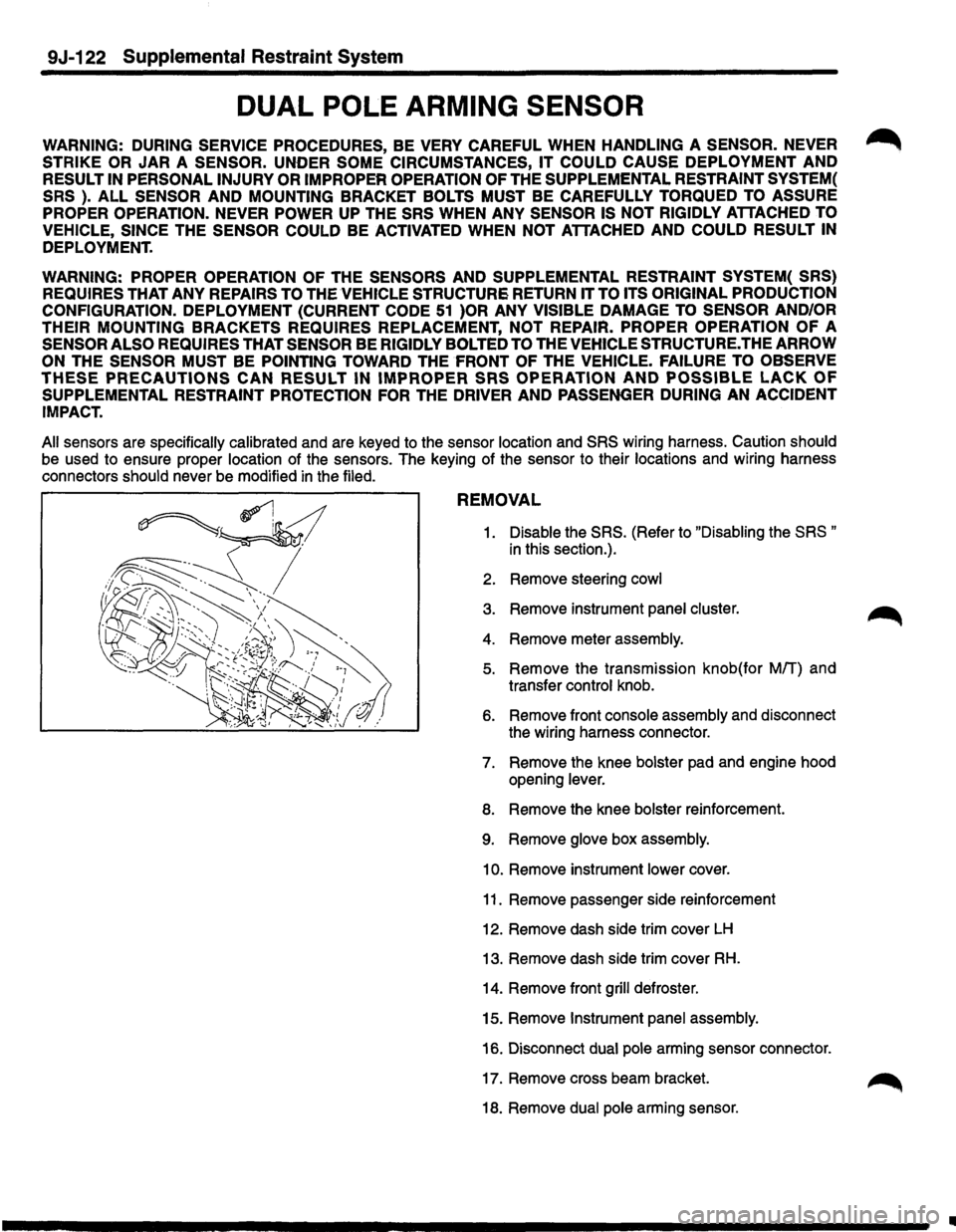
REMOVAL
1. Disable the SRS. (Refer to "Disabling the SRS "
in this section.).
2. Remove steering
cowl
3. Remove instrument panel cluster. ~
4. Remove meter assembly.
5. Remove the transmission knob(for Mff) and
transfer control knob.
6. Remove front console assembly and disconnect
the wiring harness connector.
7. Remove the knee bolster pad and engine hood
opening lever.
8. Remove the knee bolster reinforcement.
9. Remove glove box assembly.
10. Remove instrument lower cover.
11. Remove passenger side reinforcement
12. Remove dash side trim cover
LH
13. Remove dash side trim cover RH.
14. Remove front grill defroster.
15. Remove
Instrument panel assembly.
16. Disconnect
dual pole arming sensor connector.
17. Remove cross beam bracket.
18. Remove
dual pole arming sensor.
II
Page 1747 of 1928
INSTALLATION
1. Install dual pole arming sensor and tighten to
specified torque.
Torque: 26N·m(19 lb·ft.).
2. Install cross beam bracket.
3. Connect dual pole arming sensor connector.
4. Install instrument panel assembly.
5. Install front grill defroster.
6. Install dash side trim cover RH.
7. Install dash side trim cover LH.
8.
Install passenger side reinforcement
9. Install instrument lower cover.
1
0. Install glove box assembly.
11. Install the knee bolster reinforcement.
12.
Install the knee bolster pad and engine hood
opening
lever.
13. Install front console assembly and connect the
wiring harness connector.
14.
Install the transmission knob(for M/T) and
transfer control knob.
15.
Install meter assembly.
16. Install instrument panel cluster.
17. Install steering cowl
18. Enable the SRS (Refer to "Enabling the SRS" in
this section.).
Supplemental :Restraint System 9J-123
Page 1756 of 1928
9J-132 Supplemental Restraint System
PASSENGER INFLATOR MODULE
WARNING: SAFETY PRECAUTIONS MUST BE FOLLOWED WHEN HANDLING A DEPLOYED INFLATOR ~
MODULE(AIR BAG). AFTER DEPLOYMENT, THE INFLATOR MODULE(AIR BAG) SURFACE MAY CONTAIN A
SMALL AMOUNT OF SODIUM HYDROXIDE, A BY-PRODUCT OF THE DEPLOYMENT REACTION, THAT IS
IRRITATING TO
THE SKIN AND EYES. MOST OF THE POWDER ON THE INFLATOR MODULE (AIR BAG )IS
HARMLESS. AS
A PRECAUTION, WEAR GLOVES AND SAFETY GLASSES WHEN HANDLING A DEPLOYED
INFLATOR MODULE (AIR BAG ), AND WASH YOUR HANDS WITH MILD SOAP AND WATER AFTERWARDS.
WARNING: WHEN CARRYING A LIVE INFLATOR MODULE (AIR BAG ), MAKE SURE THE BAG AND TRIM
COVER
ARE POINTED AWAY FROM YOU. NEVER CARRY INFLATOR MODULE (AIR BAG )BY THE WIRES OR
CONNECTOR ON
THE UNDERSIDE OF MODULE. IN THE CASE OF AN ACCIDENTAL DEPLOYMENT, THE BAG
WILL THEN DEPLOY WITH MINIMAL CHANCE OF INJURY. WHEN PLACING A LIVE INFLATOR MODULE (AIR
BAG ) ON A BENCH OR OTHER SURFACE, ALWAYS FACE BAG AND TRIM COVER UP, AWAY FROM THE
SURFACE.
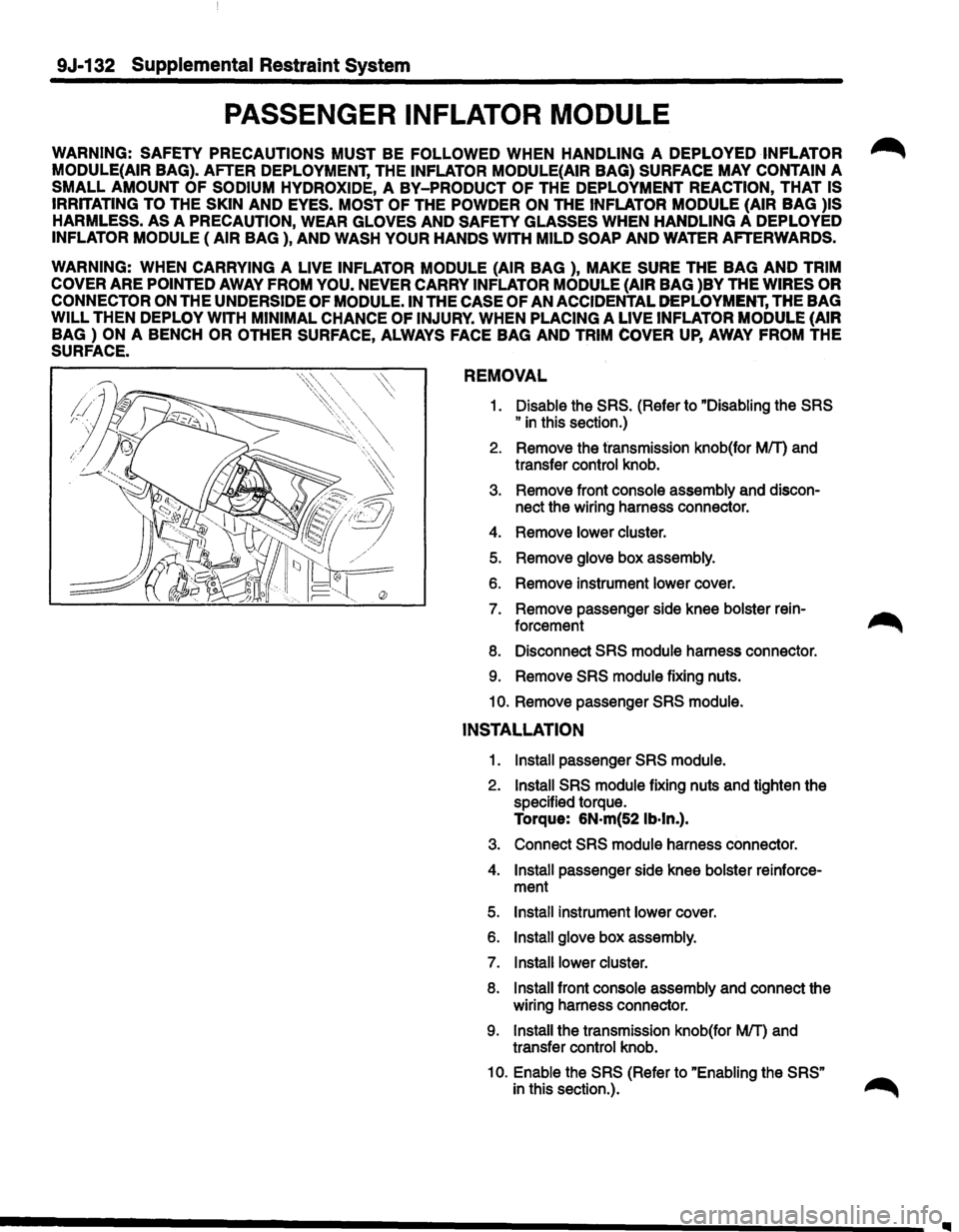
REMOVAL
1. Disable the SRS. (Refer to "Disabling the SRS
"
in this section.)
2. Remove the transmission knob(for MfT) and
transfer control knob.
3. Remove front console assembly and discon-
nect the wiring harness connector.
4. Remove lower cluster.
5. Remove glove box assembly.
6. Remove instrument lower cover.
7. Remove passenger side knee bolster rein-
forcement
8. Disconnect SRS module harness connector.
9. Remove SRS module fixing nuts.
10. Remove passenger SRS module.
INSTALLATION
1. Install passenger SRS module.
2. Install SRS module fixing nuts and tighten the
specified torque.
Torque: 6N·m(52 lb·ln.).
3. Connect SRS module harness connector.
4. Install passenger side knee bolster reinforce-
ment
5. Install instrument lower cover.
6. Install glove box assembly.
7. Install lower cluster.
8. Install front console assembly and connect the
wiring harness connector.
9. Install the transmission knob(for MfT) and
transfer control knob.
1
o. Enable the SRS (Refer to "Enabling the SRS" ~
in this section.). ,...,......,..
IIIII
Page 1783 of 1928
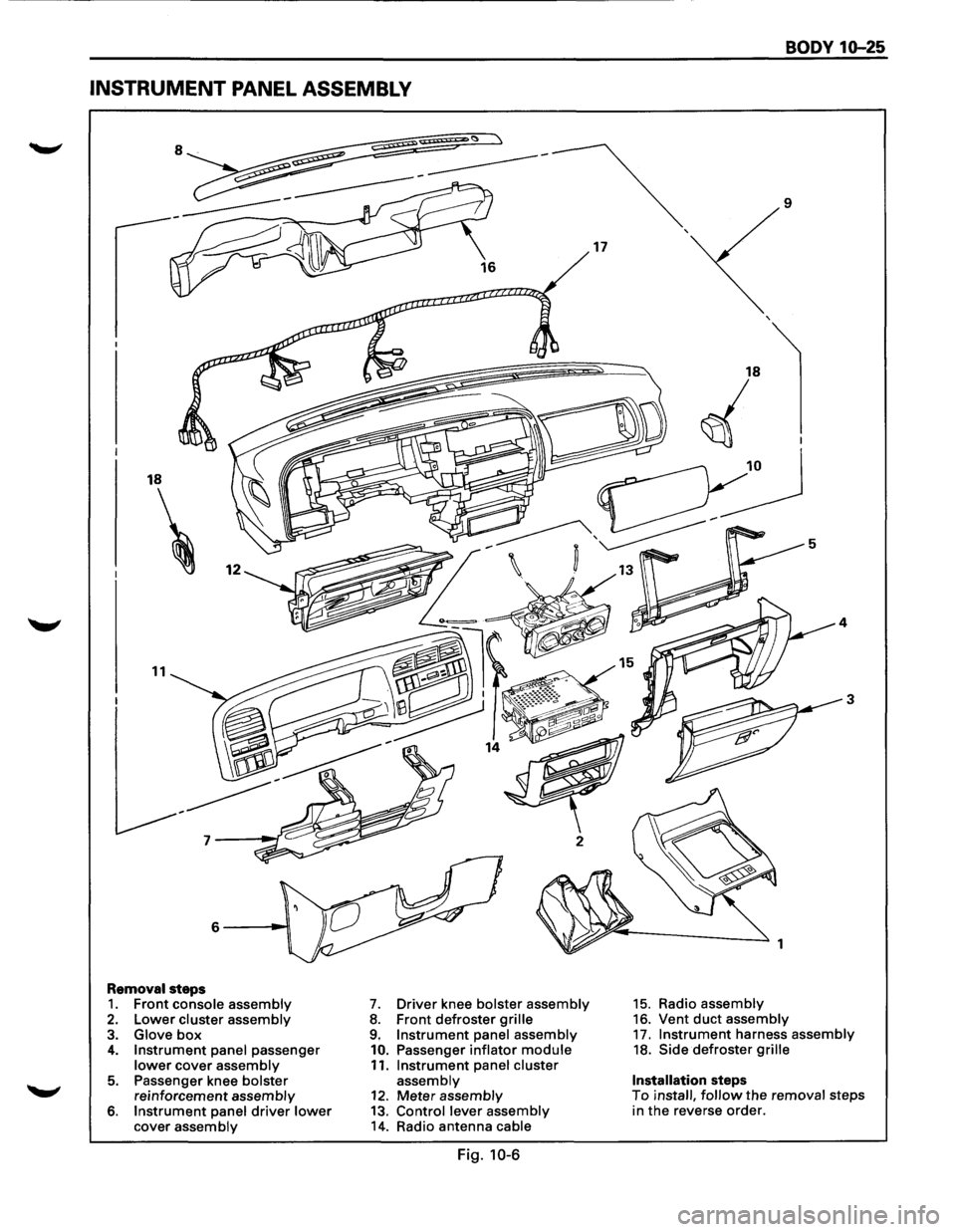
INSTRUMENT PANEL ASSEMBLY
18
11
Removal steps 1. Front console assembly 2. Lower cluster assembly 3. Glove box 4. Instrument panel passenger lower cover assembly
5. Passenger knee bolster reinforcement assembly 6. Instrument panel driver lower cover assembly
7. Driver knee bolster assembly 8. Front defroster grille 9. Instrument panel assembly
10. Passenger inflator module 11. Instrument panel cluster assembly 12. Meter assembly 13. Control lever assembly 14. Radio antenna cable
Fig. 10-6
17
BODY 10-25
9
3
1
15. Radio assembly 16. Vent duct assembly 17. Instrument harness assembly 18. Side defroster grille
Installation steps To install, follow the removal steps
in the reverse order.