boot ISUZU TROOPER 1995 Workshop Manual
[x] Cancel search | Manufacturer: ISUZU, Model Year: 1995, Model line: TROOPER, Model: ISUZU TROOPER 1995Pages: 1928
Page 6 of 1928
OA-2 GENERAL INFORMATION
1.
2.
3.
HOW TO USE THE MANUAL
Find the applicable section by referring to the
table
of contents.
4. In the beginning of each section (with the de
scription
of service operations between them,
as a rule), the General Description and the
Diagnosis give
information for the related
malfunctions and diagnosis. And, in the
following portion, the service data or the special
tools necessary
for the service operations of the
section are gathered together under
"Main Data
and
Specifications" and the "Special Tools", for
at-a-glance reference.
Each
section is basically arranged in the
following order headin~:
General description
Diagnosis
On-vehicle service
Unit repair
Main data and specifications
Special tools
The service operations are in
two groups: one is
the
"On-vehicle service" where operations can
be directly performed on the vehicle, and the
other is
the "Unit repair" where the operations
are done on the
work bench after removing the
unit
from the vehicle.
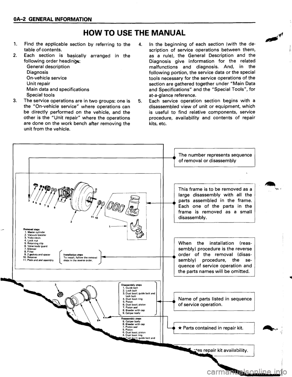
5. Each service operation section begins with a
disassembled
view of unit or equipment, which
is useful
to find relative components, service
procedure, availability and contents
of repair
kits, etc.
,..---------------------------+--e The number represents sequence of removal or disassembly
Removal steps 1. Master cylinder 2. Vacuum booster 3. Yoke clevis 4. Lock nut 5. Retaining clip 6. Valve body guard 7. Silencer 8. Filter 9. 2 gaskets and spacer 10. Retainer 11. Plate and seal assembly (
Installation steps To install, follow the remo ... al steps in the reverse order.
Disassembly steps 1. Guide bolt 2. Lock bolt 3. Dust boot; guide bolt and lock bolt 4. Dust boot ring
5. Piston 6. Dust boot; piston
7. Piston seal B. Bleeder with cap 9. Caliper body
Reassembly steps 9. Caliper body 8. Bleeder with cap 7. Piston seal 5. Piston 6. Dust boot; piston 4. Dust boot ring nust •"·•t; guide bolt and
This frame is to be removed as a
large disassembly
with all the
parts assembled in the frame.
Each one
of the parts in the
frame is removed as a small
disassembly.
When the installation (reas
sembly) procedure is the reverse
order of the removal (disas
sembly) procedure, the se
quence
of service operation and
the parts names
will be omitted.
Name
of parts listed in sequence
of service operation.
* Parts contained in repair kit.
•
-
.,... .
Page 158 of 1928
383-2 STEERING LINKAGE
ON-VEHICLE SERVICE
CENTER TRACK ROD ASSEMBL V
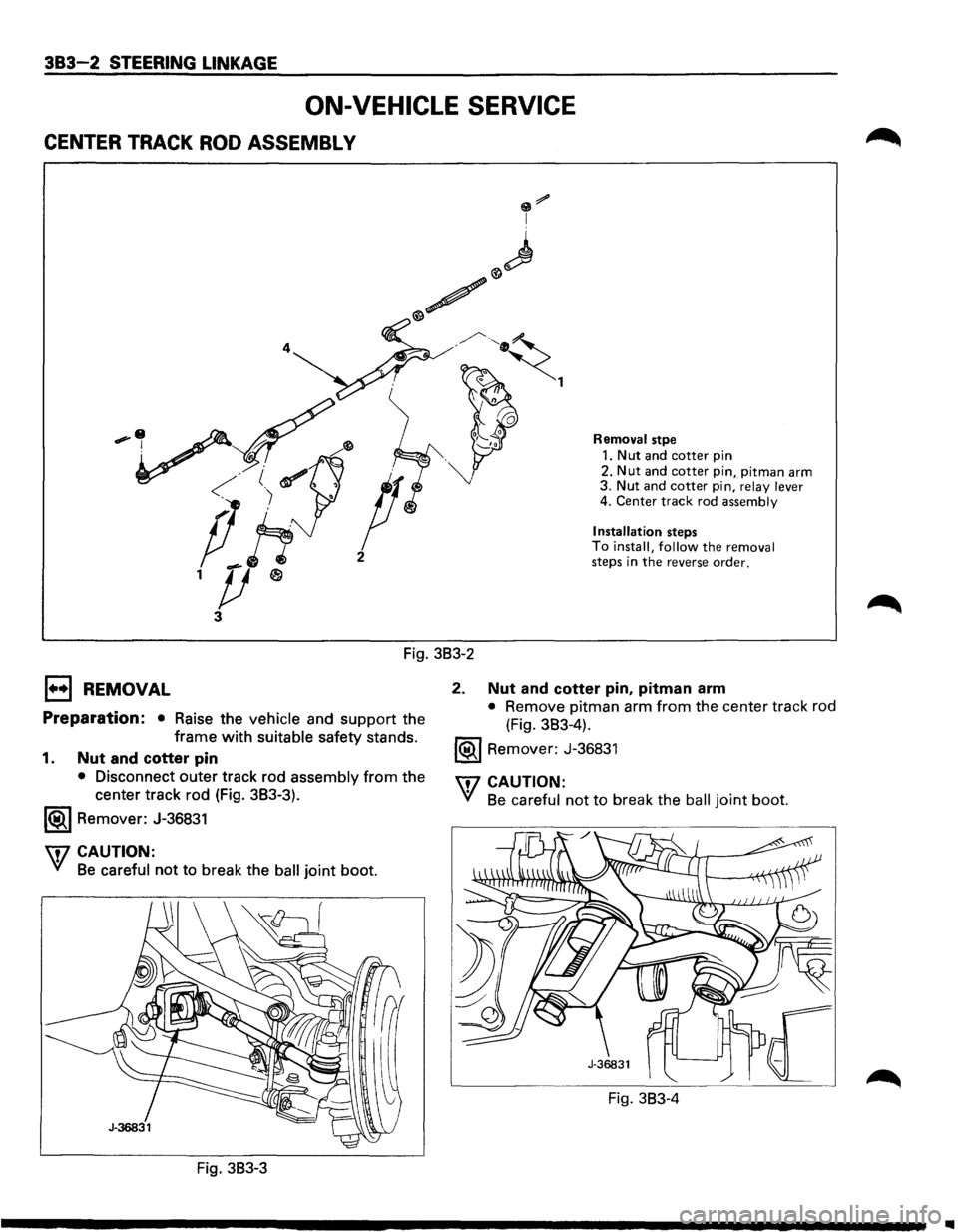
Removal stpe
1. Nut and cotter pin
2.
Nut and cotter pin, pitman arm 3. Nut and cotter pin, relay lever 4. Center track rod assembly
Installation
steps To install, follow the removal steps in the reverse order.
Fig. 3B3-2
1••1 REMOVAL
Preparation: • Raise the vehicle and support the
frame
with suitable safety stands.
1. Nut and cotter pin
• Disconnect outer track rod assembly from the
center track rod (Fig. 3B3-3).
1®.1 Remover: J-36831
U7 CAUTION:
V/ Be careful not to break the ball joint boot.
Fig. 3B3-3
2. Nut and cotter pin, pitman arm
• Remove pitman arm from the center track rod
(Fig. 3B3-4).
1®1 Remover: J-36831
\f7 CAUTION:
VI Be careful not to break the ball joint boot.
Fig. 3B3-4
..
Page 159 of 1928
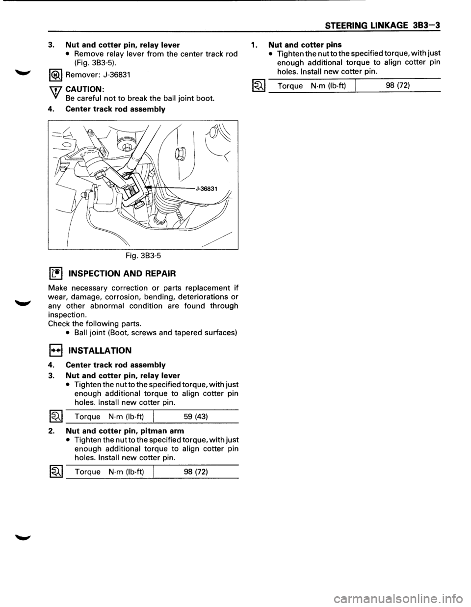
3. Nut and cotter pin, relay lever
• Remove relay lever from the center track rod
(Fig. 3B3-5).
1®.1 Remover: J-36831
\flCAUTION:
'VI Be careful not to break the ball joint boot.
4. Center track rod assembly
Fig. 3B3-5
Wtl INSPECTION AND REPAIR
~
Make necessary correction or parts replacement if
wear, damage, corrosion, bending, deteriorations or
any other abnormal condition are found through
inspection.
Check the
following parts.
• Ball joint (Boot, screws and tapered surfaces)
1••1 INSTALLATION
4. Center track rod assembly
3. Nut and cotter pin, relay lever
• Tighten the nutto the specified torque, with just
enough additional torque to align cotter pin
holes. Install new cotter pin.
~~~ Torque N·m (lb·ft) 59 (43)
2. Nut and cotter pin, pitman arm
• Tighten the nut to the specified torque, with just
enough additional torque to align cotter pin
holes. Install new cotter pin.
1~1 Torque N-m (lb·ft) 98 (72)
1.
STEERING LINKAGE 383-3
Nut and cotter pins
• Tighten the nutto the specified torque, with just
enough
additional torque to align cotter pin
holes. Install new cotter pin.
I~I_T_o_rq..;...u_e_N_·m_(l_b_·ft_) ___t_ ___ 9_8_(7_2_) __ _
Page 160 of 1928
383 - 4 STEERING LINKAGE
OUTER TRACK ROD ASSEMBLY
1+•1 REMOVAL
Fig. 3B3-6
2.
Preparation: • Remove wheel and tire assembly.
Refer to "Wheels and tires" in
section
3E. ~
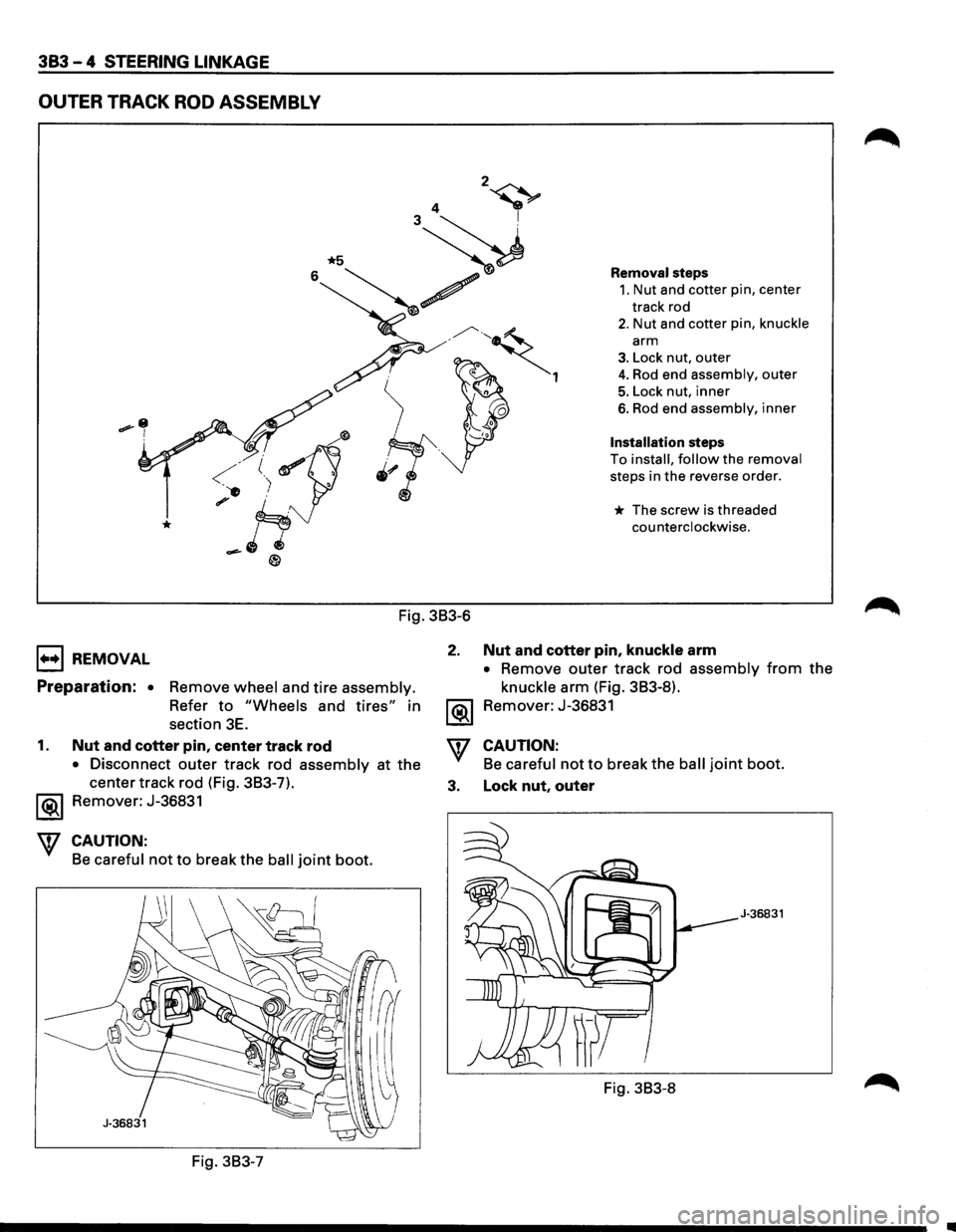
Removal steps
1. Nut and cotter pin, center
track rod
2. Nut and cotter pin, knuckle
arm
3. Lock nut, outer
4. Rod end assembly, outer
5. Lock nut, inner
6. Rod end assembly, inner
Installation steps
To install, follow the removal
steps in the reverse order.
* The screw is threaded
counterclockwise.
Nut and cotter pin, knuckle arm
• Remove outer track rod assembly from the
knuckle arm (Fig. 3B3-8).
Remover: J-36831
1. Nut and cotter pin, center track rod
• Disconnect outer track rod assembly at the
center track rod (Fig. 3B3-7).
'\f CAUTION:
Be careful not to break the ball joint boot.
3. Lock nut, outer Remover: J-36831
CAUTION:
Be careful not to break the ball joint boot.
J-36831
Fig. 3B3-8
Fig. 3B3-7
Page 161 of 1928
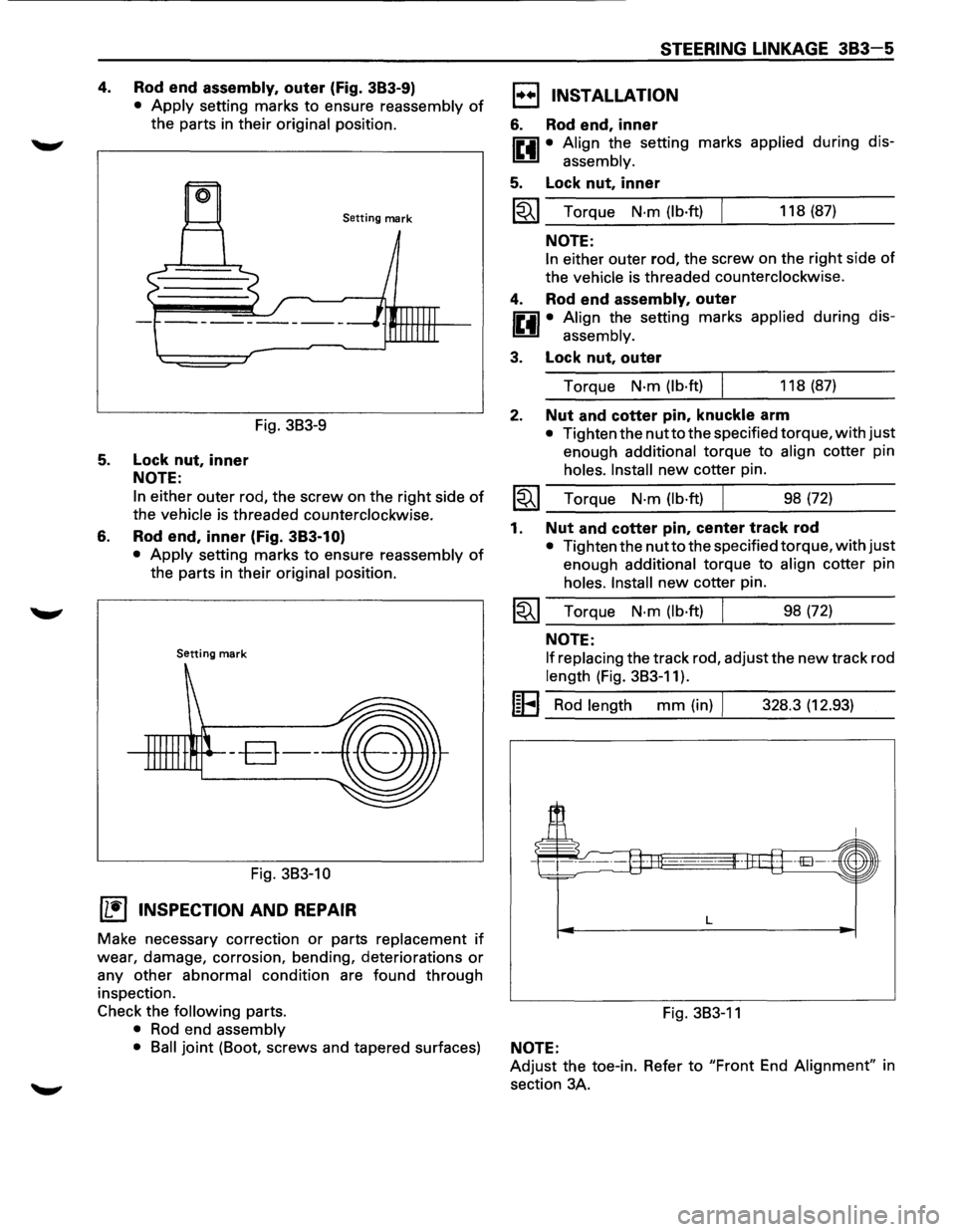
4. Rod end assembly, outer (Fig. 383-9)
• Apply setting marks to ensure reassembly of
the parts in their original position.
Setting mark
Fig. 3B3-9
5. Lock nut, inner
NOTE:
6.
In either outer rod, the screw on the right side of
the vehicle is threaded counterclockwise.
Rod end, inner (Fig. 383-1 O)
• Apply setting marks to ensure reassembly of
the parts in their original position.
Setting mark
--B--
Fig. 3B3-10
(1!] INSPECTION AND REPAIR
Make necessary correction or parts replacement if
wear, damage, corrosion, bending, deteriorations or
any other abnormal condition are found through
inspection.
Check the
following parts.
• Rod end assembly
STEERING LINKAGE 383-5
1••1 INSTALLATION
6. Rod end, inner
IP.il • Align the setting marks applied during dis-
~ assembly.
5. Lock nut, inner
~~~ Torque N·m (lb·ft) 118 (87)
NOTE:
In either outer rod, the screw on the right side of
the vehicle is threaded counterclockwise.
4. Rod end assembly, outer
IP.il • Align the setting marks applied during dis-
~ assembly.
3. Lock nut, outer
Torque N·m (lb·ft) 118 (87)
2. Nut and cotter pin, knuckle arm
• Tighten the nutto the specified torque, with just
enough additional torque to align cotter pin
holes. Install new cotter pin.
~~~ Torque N·m (lb·ft) ___ ______._ ___ _ 98 (72)
1. Nut and cotter pin, center track rod
• Tighten the nutto the specified torque, with just
enough additional torque to align cotter pin
holes. Install new cotter pin.
~~~ Torque N·m (lb·ft) 98 (72)
NOTE:
If replacing
the track rod, adjust the new track rod
length (Fig. 3B3-11).
I~EI Rod length mm (in) I 328.3 (12.93)
L
Fig. 3B3-11
• Ball joint (Boot, screws and tapered surfaces) NOTE:
Adjust the toe-in. Refer to "Front End Alignment" in
section 3A.
Page 168 of 1928
3C-4 FRONT SUSPENSION
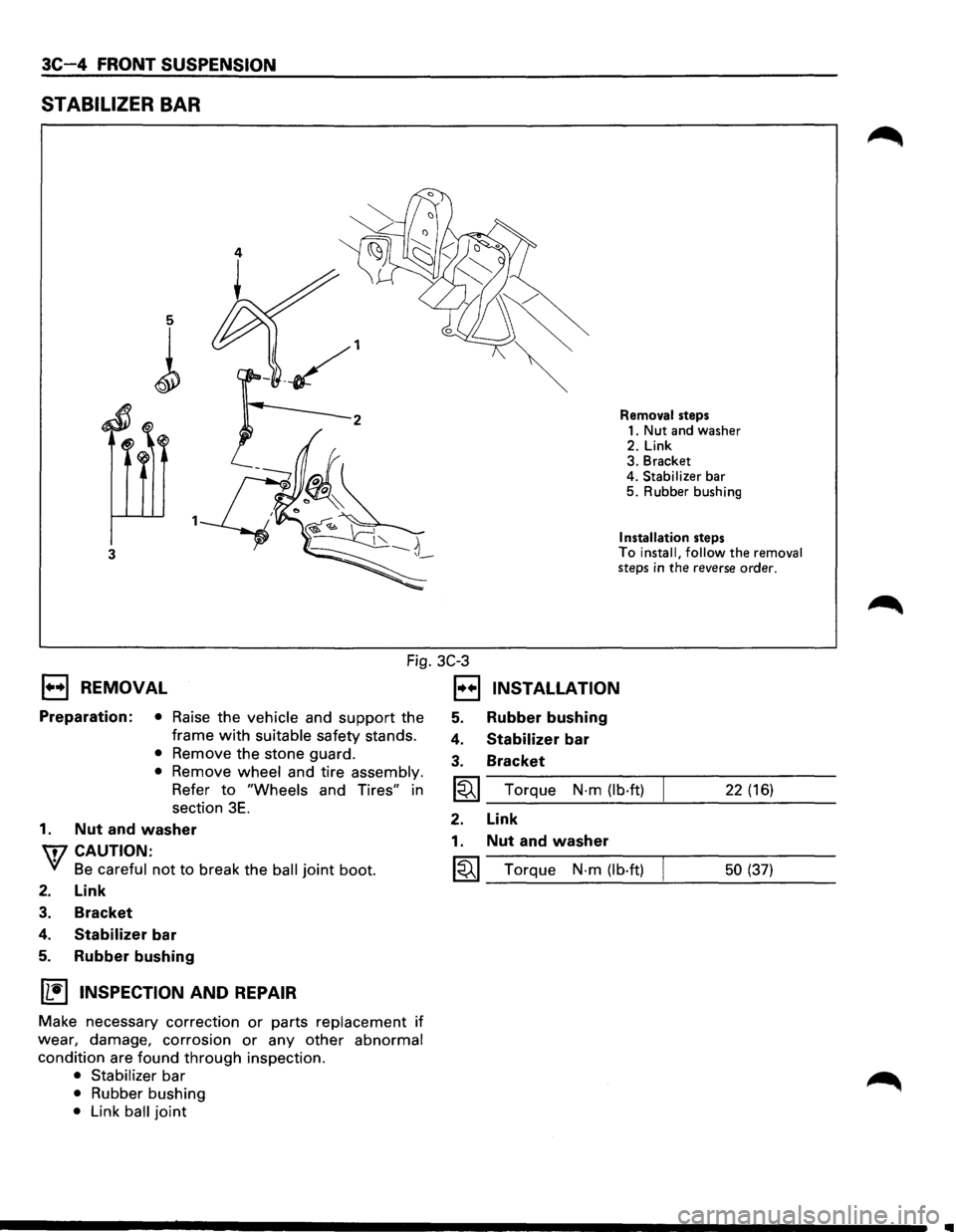
STABILIZER BAR
5
l
3
Removal steps
1. Nut and washer
2. Link 3. Bracket
4. Stabilizer bar 5. Rubber bushing
Installation steps To install, follow the removal steps in the reverse order.
Fig. 3C-3
1••1 REMOVAL
Preparation: • Raise the vehicle and support the
frame
with suitable safety stands.
• Remove the stone guard.
• Remove wheel and tire assembly.
Refer to "Wheels and Tires" in
section
3E.
1. Nut and washer
W CAUTION:
VI Be careful not to break the ball joint boot.
2. Link
3. Bracket
4. Stabilizer bar
5. Rubber bushing
~ INSPECTION AND REPAIR
Make necessary correction or parts replacement if
wear, damage, corrosion or any other abnormal
condition are found through inspection.
• Stabilizer bar
• Rubber bushing
• Link ball joint
1••1 INSTALLATION
5. Rubber bushing
4. Stabilizer bar
3. Bracket
~ Torque N·m (lb·ft) 22 (16)
2. Link
1. Nut and washer
~ Torque N-m (lb·ft) 50 (37)
..
Page 171 of 1928
FRONT SUSPENSION 3C-7
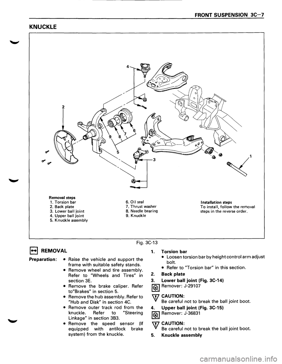
KNUCKLE
2
~,
Removal steps 1. Torsion bar 6. Oil seal Installation steps 2.
Back plate 7. Thrust washer To install, follow the removal steps in the reverse order. 3. Lower ball joint 8. Needle bearing
4. Upper
ball joint 9. Knuckle
5. Knuckle assembly
Fig. 3C-13
1••1 REMOVAL
Preparation: • Raise the vehicle and support the
frame
with suitable safety stands.
• Remove wheel and tire assembly.
Refer to
"Wheels and Tires" in
section
3E.
• Remove the brake caliper. Refer
to"Brakes" in section 5.
• Remove the hub assembly. Refer to
"Hub and Disk" in section 4C.
• Remove outer track rod from the
knuckle. Refer to
"Steering
Linkage" in section 3B3.
• Remove the speed sensor (If
equipped with antilock brake
system)
from the knuckle. 1.
Torsion bar
• Loosen
torsion bar by height control arm adjust
bolt.
• Refer to "Torsion bar" in this section.
2. Back plate
3. Lower ball joint (Fig. 3C-14)
1®.1 Remover: J-291 07
'\f7 CAUTION:
'(! Be careful not to break the ball joint boot.
4. Upper ball joint (Fig. 3C-15)
1®.1 Remover: J-36831
'\f7 CAUTION:
'(! Be careful not to break the ball joint boot.
5. Knuckle assembly
Page 175 of 1928
\fl CAUTION:
'V Be careful not to break the ball joint boot.
3. Upper ball joint
4. Bolt and plate
5. Nut assembly
6. Camber shims
• Note the positions and number of shims.
7. Caster shims
• Note the positions and number of shims.
8. Upper control arm assembly
9. Nut
10. Plate
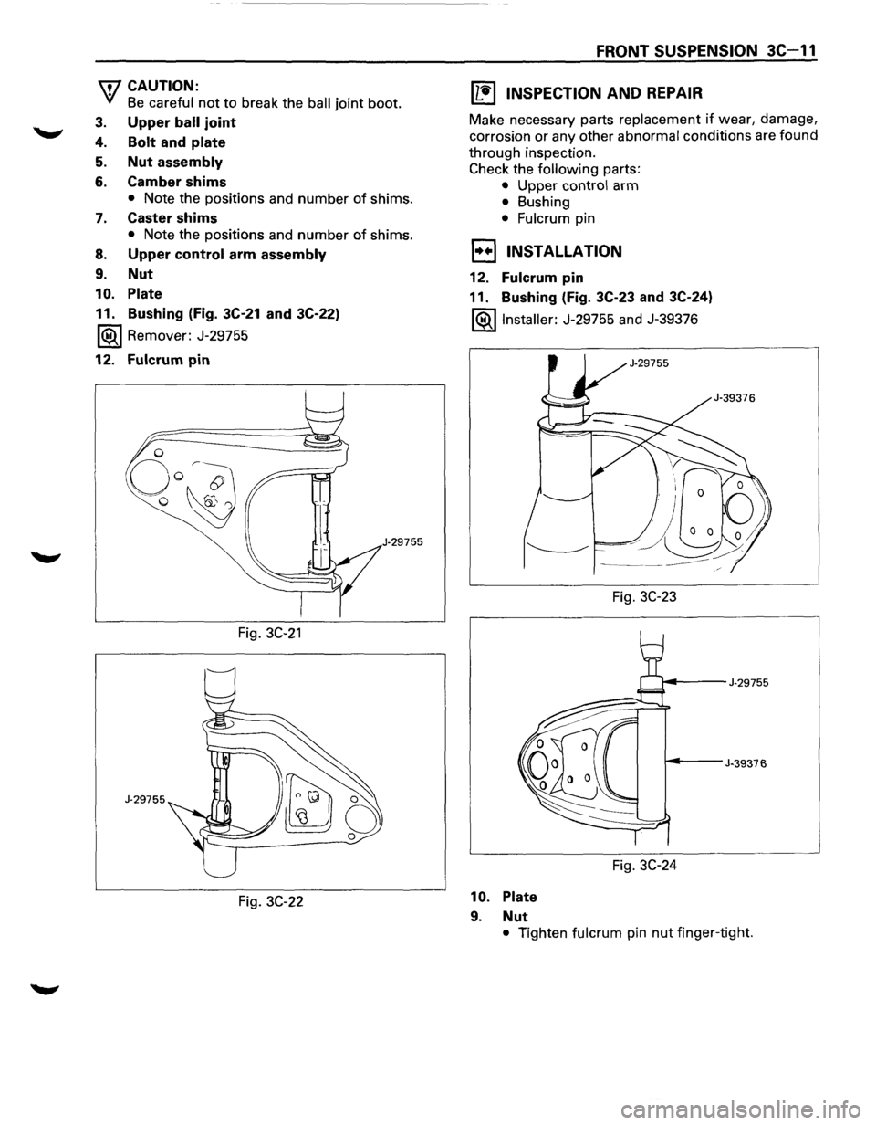
11. Bushing (Fig. 3C-21 and 3C-22)
1®.1 Remover: J-29755
12. Fulcrum pin
J·29755
Fig. 3C-21
J-29755
Fig. 3C-22
FRONT SUSPENSION 3C-11
IL•I INSPECTION AND REPAIR
Make necessary parts replacement if wear, damage,
corrosion or any other abnormal conditions are found
through inspection.
Check the following parts:
• Upper control arm
• Bushing
• Fulcrum pin
1••1 INSTALLATION
12. Fulcrum pin
11. Bushing (Fig. 3C-23 and 3C-24)
l®.llnstaller: J-29755 and J-39376
Fig.
3C-23
~---J-29755
~--J-39376
Fig. 3C-24
10. Plate
9. Nut
• Tighten fulcrum pin nut finger-tight.
Page 180 of 1928
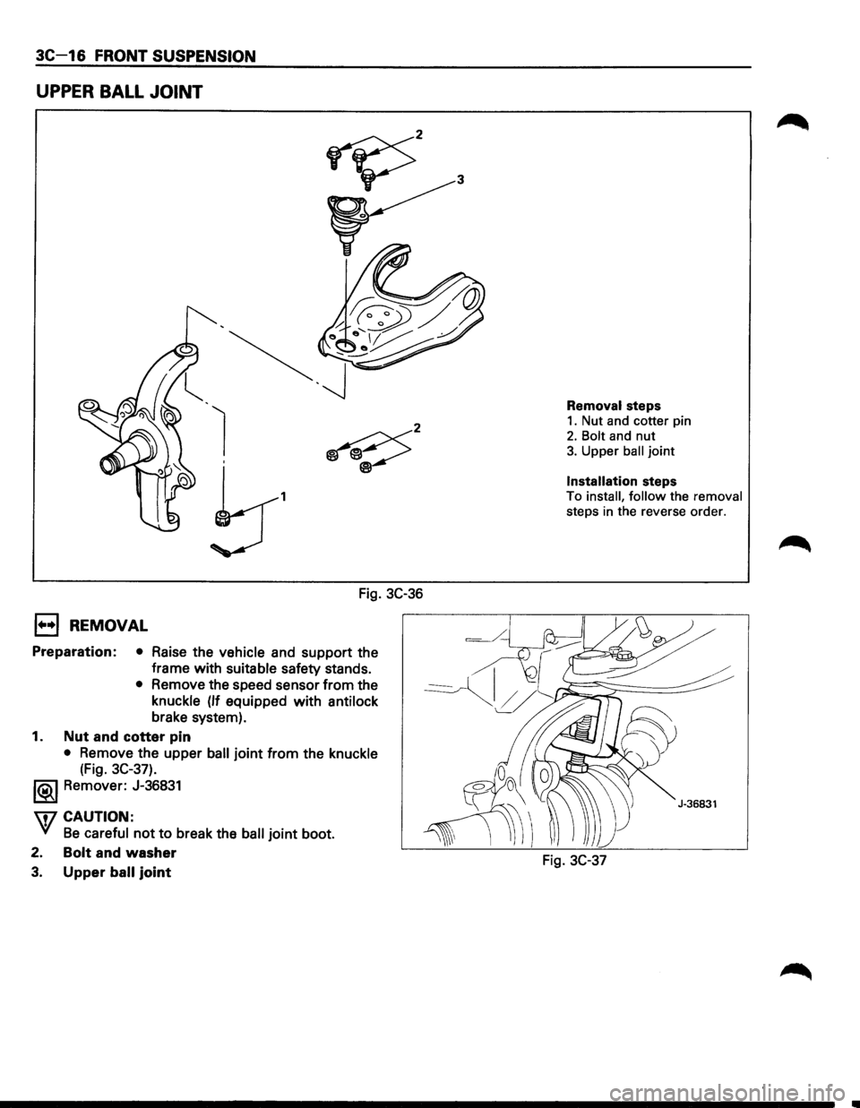
3C-16 FRONT SUSPENSION
UPPER BALL JOINT
1
Fig. 3C-36
E) REMOVAL
Preparation: • Raise the vehicle and support the
frame with
suitable safety stands.
• Remove the speed sensor from the
knuckle
(If equipped with antilock
brake system).
1. Nut and cotter pin
• Remove the upper ball joint from the knuckle
(Fig. 3C-37).
l®..l Remover: J-36831
\fl CAUTION:
VI Be careful not to break the ball joint boot.
2.
Bolt and washer
3. Upper ball joint
Removal steps
1. Nut and cotter pin
2. Bolt and nut
3. Upper ball joint
Installation steps
To install, follow the removal
steps in the reverse order.
Fig. 3C-37
Page 181 of 1928
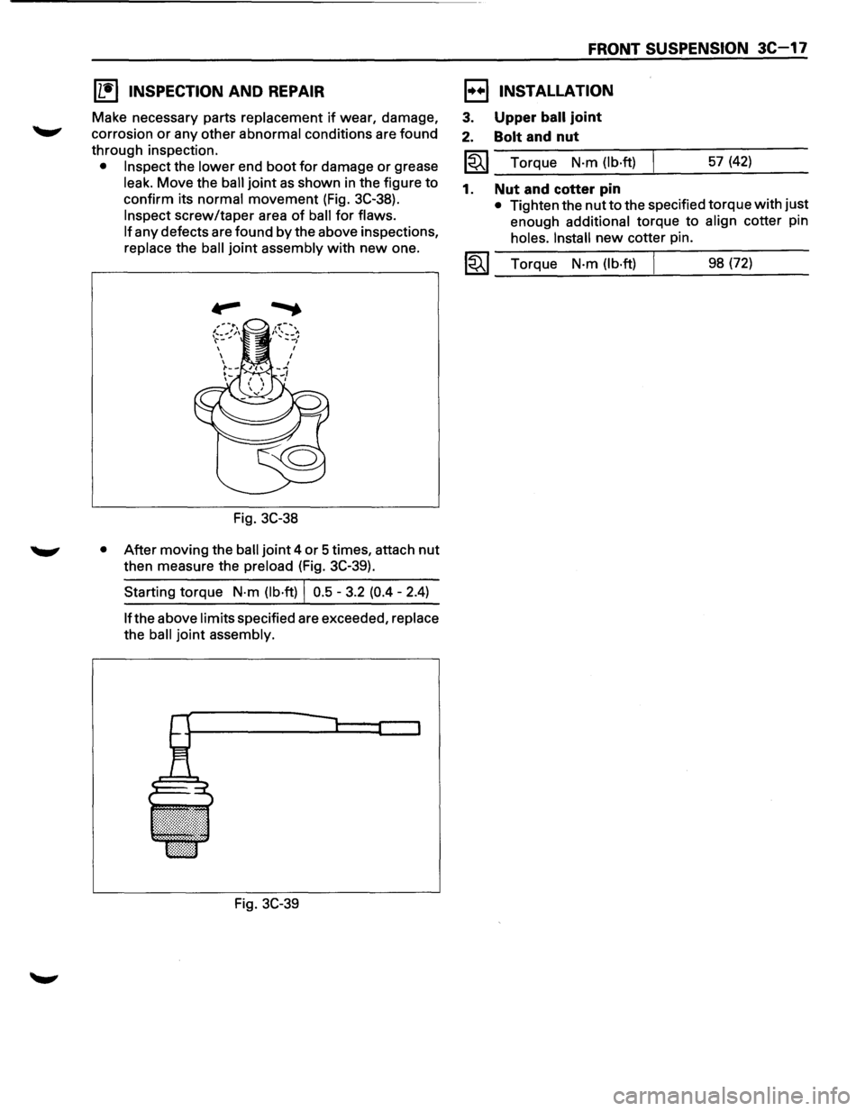
[L!) INSPECTION AND REPAIR
Make necessary parts replacement if wear, damage,
corrosion
or any other abnormal conditions are found
through inspection.
• Inspect the lower end boot for damage or grease
leak. Move the ball joint as shown in the figure to
confirm its normal movement (Fig. 3C-38).
Inspect screw/taper area of ball for flaws.
If
any defects are found by the above inspections,
replace the ball joint assembly with new one.
Fig. 3C-38
• After moving the ball joint 4 or 5 times, attach nut
then measure the preload (Fig. 3C-39).
Starting torque
N·m (lb·ft) I 0.5 -3.2 (0.4 - 2.4)
lfthe above limits specified are exceeded, replace
the ball joint assembly.
Fig. 3C-39
FRONT SUSPENSION 3C-17
1••1 INSTALLATION
3. Upper ball joint
2. Bolt and nut
~~~--T~o_rq~u_e __ N_·m~(l_b_·ft~)_L _____ 5_7_(4_2_) ____ _
1. Nut and cotter pin
• Tighten the nut to the specified torque with just
enough
additional torque to align cotter pin
holes. Install new cotter pin.
1-"i"' I Torque N·m (lb·ft) j 98 (72) ~---~--~~--------