steering ISUZU TROOPER 1995 Owner's Manual
[x] Cancel search | Manufacturer: ISUZU, Model Year: 1995, Model line: TROOPER, Model: ISUZU TROOPER 1995Pages: 1928
Page 135 of 1928
FRONT END ALIGNMENT 3A-3
ON-VEHICLE SERVICE
INSPECTION
Before making any adjustments affecting caster,
camber or toe-in, the following front end inspection
should be made.
I L•IINSPECT
1. Tires for proper inflation pressure. Refer to
"Wheels and Tires" in section 3E.
2. Front wheel bearings for proper adjustment.
Refer to "Front Wheel Drive" in section 4C.
3. Ball joints, tie rod ends and relay rods. If
excessive looseness is noted, correct before
adjusting. Refer
to "Steering Linkage" in section
3B3.
4. Wheel and tires for run-out. Refer to "Wheels
and Tires" in section 3E.
5. Trim height. If not within specifications, the
correction
must be made before adjusting caster.
6. Steering gear for looseness at the frame.
7. Shock absorbers for leaks or any noticeable
noise.
Refer
to "Front Suspension" in section 3C.
8. Control arms or stabilizer bar attachment for
looseness. Refer to "Front Suspension" in section
3C.
9. Alignment equipment. Follow the manufacturer's
instructions.
10. Level of the vehicle. The vehicle must be on a
level surface.
TRIM HEIGHT ADJUSTMENT
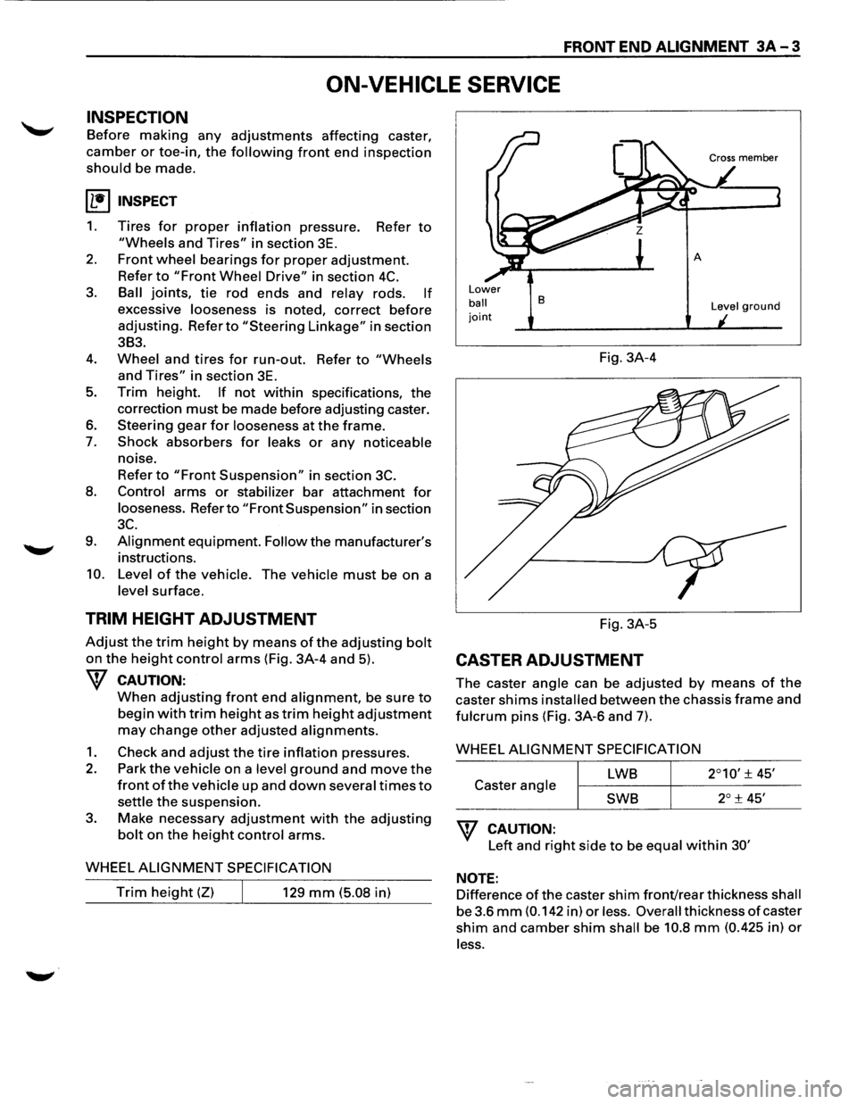
Adjust the trim height by means of the adjusting bolt
on the height control arms (Fig. 3A-4 and 5).
W CAUTION:
When adjusting front end alignment, be sure to
begin with trim height as trim height adjustment
may change other adjusted alignments.
1. Check and adjust the tire inflation pressures.
2. Park the vehicle on a level ground and move the
front of the vehicle up and down several times to
settle the suspension.
3. Make necessary adjustment with the adjusting
bolt on the height control arms.
WHEEL
ALIGNMENT SPECIFICATION
Trim height (Z) 129 mm (5.08 in)
Lower
ball joint
B
Fig. 3A-4
Fig. 3A-5
CASTER ADJUSTMENT
Level ground
The caster angle can be adjusted by means of the
caster shims installed between the chassis frame and
fulcrum pins (Fig. 3A-6 and 7).
WHEEL
ALIGNMENT SPECIFICATION
LWB
Caster angle
SWB
W CAUTION:
Left and right side to be equal within 30'
NOTE:
Difference of the caster shim front/rear thickness shall
be 3.6
mm (0.142 in) or less. Overall thickness of caster
shim and camber shim shall be 10.8 mm (0.425 in) or
less.
Page 137 of 1928
TOE-IN ADJUSTMENT
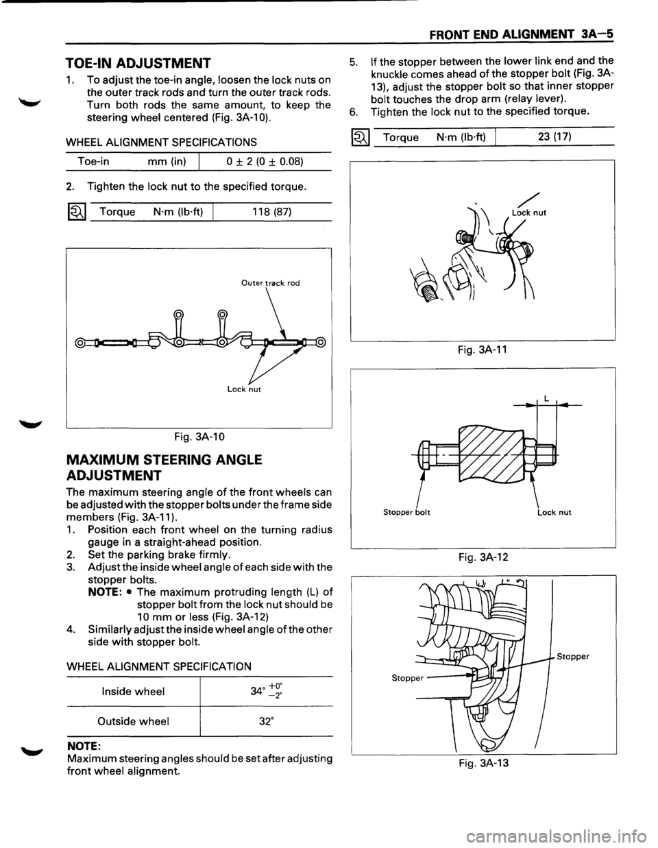
1. To adjust the toe-in angle, loosen the lock nuts on
the outer track rods and turn the outer track rods.
Turn both rods the same amount, to keep the
steering
wheel centered (Fig. 3A-1 0).
WHEEL ALIGNMENT SPECIFICATIONS
Toe-in mm (in) I 0 ± 2 (0 ± 0.08)
2. Tighten the lock nut to the specified torque.
~~~ Torque N·m (lb·ft) 118 (87)
Outer track rod
Lock nut
Fig. 3A-10
MAXIMUM STEERING ANGLE
ADJUSTMENT
The maximum steering angle of the front wheels can
be adjusted
with the stopper bolts under the frame side
members (Fig. 3A-11 ).
1. Position each front wheel on the turning radius
gauge in a straight-ahead position.
2. Set the parking brake firmly.
3. Adjust the inside wheel angle of each side with the
stopper
bolts.
NOTE: • The maximum protruding length (L) of
stopper bolt from the lock nut should be
10 mm or less (Fig. 3A-12)
4. Similarly adjust the inside wheel angle of the other
side
with stopper bolt.
WHEEL ALIGNMENT SPECIFICATION
Inside wheel
34° ~~:
Outside wheel 32°
NOTE:
Maximum steering angles should be set after adjusting
front wheel alignment.
FRONT END ALIGNMENT 3A-5
5. If the stopper between the lower link end and the
knuckle comes ahead of the stopper bolt (Fig. 3A-
13), adjust the stopper
bolt so that inner stopper
bolt touches the drop arm (relay lever).
6. Tighten the lock nut to the specified torque.
~~~ Torque N·m (lb·ft) 23 (17)
Fig. 3A-11
L
Stopper bolt Lock nut
Fig. 3A-12
Stopper
Fig. 3A-13
Page 138 of 1928
3A-6 FRONT END ALIGNMENT
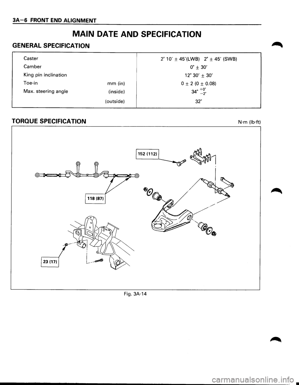
MAIN DATE AND SPECIFICATION
GENERAL SPECIFICATION
Caster
Camber
King pin inclination
Toe-in
Max. steering
angle
TORQUE SPECIFICATION
mm (in)
(inside)
(outside)
2° 10' ± 45'(LWB) 2° ± 45' (SWB)
oo ± 30'
12° 30' ± 30'
0 ± 2 (0 ± 0.08)
34° ~~:
32°
1152 (112)~ ~1
,I~
Fig. 3A-14
N·m (lb·ft)
Page 139 of 1928
POWER STEERING GEAR AND PUMP 381 -1
SECTION 381
POWER STEERING GEAR AND PUMP
w CAUTION:
When fasteners are removed, always reinstall them at the same location from which they were removed.
If a fastener needs to be replaced, use the correct part number fastener for that application. If the correct
part
number fastener is not available, a fastener of equal size and strength (or stronger) may be used.
Fasteners
that are not reused, and those requiring thread locking compound, will be called out. The correct
torque value must be used when installing fasteners that require it. If the above conditions are not
followed, parts or system damage could result.
CONTENTS
General Description ............................ 3B1- 1
Steering Wheel Free Play Adjustment .... 3B1-5
Power Steering
Gear........................ 3B1-1
Steering Gear ................................ 3B1-6
Hydraulic Pump .............................. 3B1- 1
Power Steering Pump ...................... 3B1-8
Pressure Switch
............................. 3B1-1
Unit Repair ...................................... 3B1- 9
Power Steering System Test
................. 3B1-3
Steering Gear ................................ 3B1-9
On-Vehicle Service ............................. 3B1- 4
Power Steering Pump ...................... 3B1-14
Maintenance
................................. 3B1- 4
Main Data and Specifications ................ 3B1-17
Fluid Level .................................... 3B1- 4 General Specifications ...................... 3B1-17
Bleeding The Power Steering System .... 3B1-4
Torque Specifications ....................... 3B1-17
Bleeding Procedure ......................... 3B1-4 Special Tools.................................... 3B1-18
Flushing The Power Steering System .... 3B1-4
GENERAL DESCRIPTION
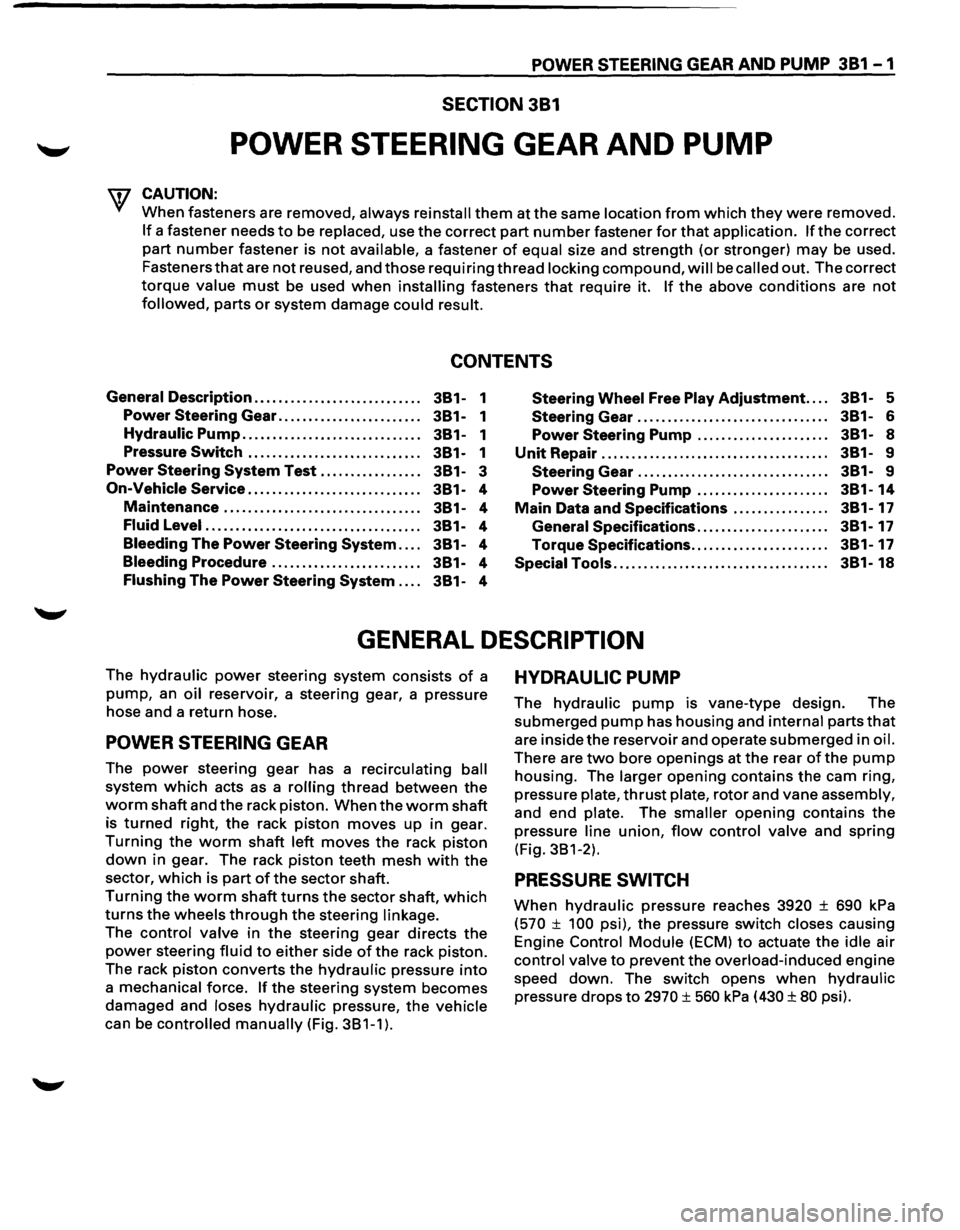
The hydraulic power steering system consists of a
pump, an oil reservoir, a steering gear, a pressure
hose and a return hose.
POWER STEERING GEAR
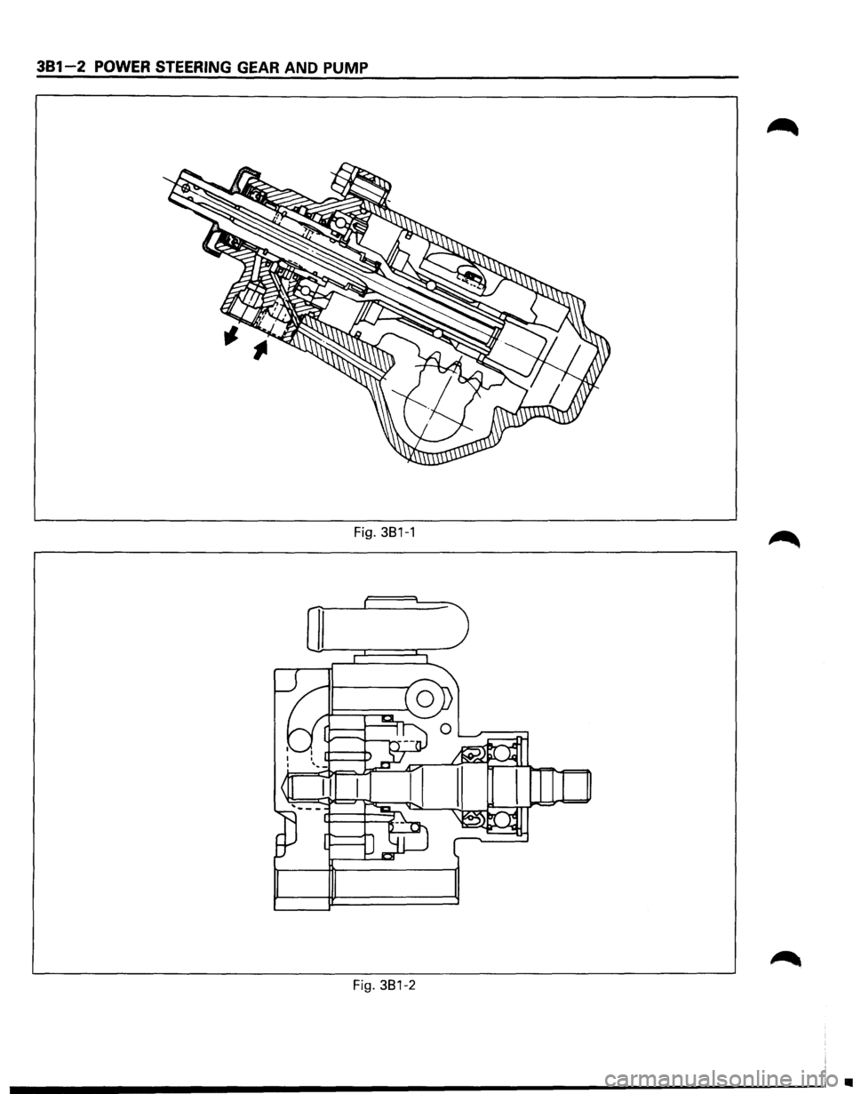
The power steering gear has a recirculating ball
system which acts as a rolling thread between the
worm shaft and the rack piston. When the worm shaft
is
turned right, the rack piston moves up in gear.
Turning the worm shaft left moves the rack piston
down in gear. The rack piston teeth mesh with the
sector, which is part ofthe sector shaft.
Turning the worm shaft turns the sector shaft, which
turns the wheels through the steering linkage.
The control valve in the steering gear directs the
power steering fluid to either side of the rack piston.
The rack
piston converts the hydraulic pressure into
a mechanical force. If the steering system becomes
damaged and loses hydraulic pressure, the vehicle
can be controlled manually (Fig. 381-1).
HYDRAULIC PUMP
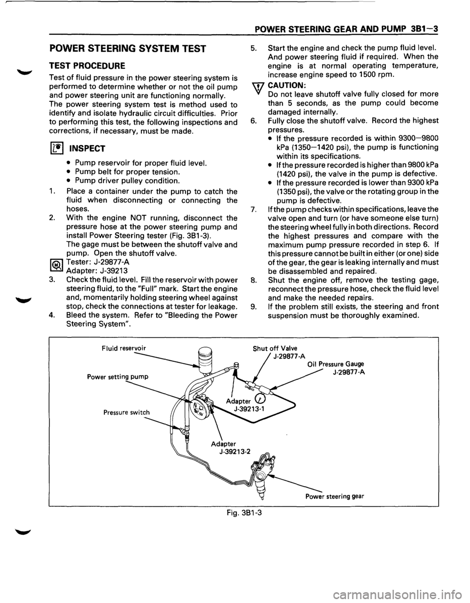
The hydraulic pump is vane-type design. The
submerged pump has housing and internal parts that
are inside the reservoir and operate submerged in oil.
There are two bore openings at the rear of the pump
housing. The larger opening contains the cam ring,
pressure
plate, thrust plate, rotor and vane assembly,
and end plate. The smaller opening contains the
pressure
line union, flow control valve and spring
(Fig. 381-2).
PRESSURE SWITCH
When hydraulic pressure reaches 3920 ± 690 kPa
(570 ± 100 psi), the pressure switch closes causing
Engine
Control Module (ECM) to actuate the idle air
control valve to prevent the overload-induced engine
speed down. The switch opens
when hydraulic
pressure drops to 2970 ± 560 kPa (430 ± 80 psi).
Page 140 of 1928
381-2 POWER STEERING GEAR AND PUMP
Fig. 381-1
II
Fig. 381-2
•
Page 141 of 1928
POWER STEERING SYSTEM TEST
TEST PROCEDURE
Test of fluid pressure in the power steering system is
performed to determine whether
or not the oil pump
and
power steering unit are functioning normally.
The power steering system test is method used to
identify and
isolate hydraulic circuit difficulties. Prior
to performing this test, the following inspections and
corrections,
if necessary, must be made.
[!) INSPECT
• Pump reservoir for proper fluid level.
•
Pump belt for proper tension.
• Pump driver pulley condition.
1. Place a container under the pump to catch the
fluid when disconnecting or connecting the
hoses.
2. With the engine NOT running, disconnect the
pressure hose
at the power steering pump and
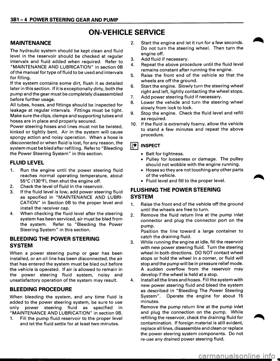
install Power Steering tester (Fig. 3B1-3).
The gage
must be between the shutoff valve and
pump.
Open the shutoff valve.
li5\l Tester: J-29877-A
~ Adapter: J-39213
3. Check the fluid level. Fill the reservoir with power
steering fluid, to the "Full" mark. Start the engine
and,
momentarily holding steering wheel against
stop, check the connections at tester
for leakage.
4. Bleed the system. Refer to "Bleeding the Power
Steering
System".
POWER STEERING GEAR AND PUMP 381-3
5. Start the engine and check the pump fluid level.
And power steering fluid if required. When the
engine is at
normal operating temperature,
increase engine speed to 1500 rpm.
U7 CAUTION:
VI Do not leave shutoff valve fully closed for more
than 5 seconds,
as the pump could become
damaged
internally.
6. Fully close the shutoff valve. Record the highest
pressures.
• If the pressure recorded is within 9300-9800
kPa (1350-1420 psi), the pump is functioning
within its specifications.
• If the pressure recorded is higher than 9800 kPa
(1420 psi), the valve in the pump is defective.
• If the pressure recorded is lower than 9300 kPa
(1350 psi), the valve or the rotating group in the
pump is defective.
7. If the pump checks within specifications, leave the
valve open and turn (or have someone else turn)
the steering
wheel fully in both directions. Record
the highest pressures and compare
with the
maximum pump pressure recorded in step
6. If
this pressure cannot be built in either (or one) side
ofthe gear, the gear is leaking internally and must
be disassembled and repaired.
8. Shut the engine off, remove the testing gage,
reconnect the pressure hose, check the
fluid level
and make the needed repairs.
9. If the problem still exists, the steering and front
suspension must be thoroughly examined.
Shut off Valve
J-29877-A
Oil Pressure Gauge
J-29877-A
Fig. 3B1-3
Page 142 of 1928
381 - 4 POWER STEERING GEAR AND PUMP
ON-VEHICLE SERVICE
MAINTENANCE
The hydraulic system should be kept clean and fluid
level in the reservoir should be checked at regular
intervals
and fluid added when required. Refer to
"MAINTENANCE AND LUBRICATION" in section OB
ofthe manual for type offluid to be used and intervals
for filling.
If the system contains some dirt, flush it as detailed
later
in this section. If it is exceptionally dirty, both the
pump and the gear must be completely disassembled
before further usage.
All tubes, hoses, and fittings should be inspected for
leakage at regular intervals. Fittings must be tight.
Make sure the clips, clamps and supporting tubes and
hoses are in
place and properly secured.
Power steering hoses and lines must not be twisted,
kinked or tightly bent. Air in the system will cause
spongy action and noisy operation. When a hose is
disconnected
or when fluid is lost, for any reason, the
system must be bled after refilling. Refer to "Bleeding
the Power Steering System" in this section.
FLUID LEVEL
1. Run the engine until the power steering fluid
reaches normal operating temperature, about
55°C (130°F), then shut the engine off.
2. Check the level of fluid in the reservoir.
3. If the fluid level is low, add power steering fluid
as specified in "MAINTENANCE AND LUBRI
CATION" in Section OB to the proper level and
install the receiver cap.
4. When checking the fluid level after the steering
system has been serviced,
air must be bled from
the system. Refer to "Bleeding the Power
Steering
System" in this section.
BLEEDING THE POWER STEERING
SYSTEM
When a power steering pump or gear has been
installed, or an oil line has been disconnected, the air
that has entered the system must be bled out before
the vehicle is operated. If air is allowed to remain in
the power steering fluid system, noisy and
unsatisfactory operation of the system may result.
BLEEDING PROCEDURE
When bleeding the system, and any time fluid is
added
to the power steering system, be sure to use
only power steering fluid as specified in
"MAINTENANCE AND LUBRICATION" in section OB.
1. Fill the pump fluid reservoir to the proper level
and let the fluid settle for at least two minutes.
2. Start the engine and let it run for a few seconds.
Do
not turn the steering wheel. Then turn the
engine off.
3. Add fluid if necessary.
4. Repeat the above procedure until the fluid level
remains constant after running the engine.
5. Raise the front end of the vehicle so that the
wheels are off the ground.
6. Start the engine. Slowly turn the steering wheel
right and left, lightly contacting the wheel stops.
7. Add power steering fluid if necessary.
8. Lower the vehicle and turn the steering wheel
slowly from lock to lock.
9. Stop the engine. Check the fluid level and refill
as required.
10.
If the fluid is extremely foamy, allow the vehicle
to stand a few minutes and repeat the above
procedure.
~ INSPECT
• Belt for tightness.
• Pulley for looseness or damage. The pulley
should not wobble with the engine running.
• Hoses so they are not touching any other parts
of the vehicle.
• Fluid level
and fill to the proper level.
FLUSHING THE POWER STEERING
SYSTEM
1. Raise the front end of the vehicle off the ground
until the wheels are free to turn.
2. Remove the fluid return line at the pump inlet
connector and plug the connector port on the
pump.
Position the line toward a large container to
catch the draining fluid.
3. While running the engine at idle, fill the reservoir
with new power steering fluid. Turn the steering
wheel in both directions. DO NOT contact wheel
stops or hold the wheel in a corner, or fluid will
stop and the pump will be in pressure relief mode.
A sudden
overflow from the reservoir may
develop if the wheel is held at a stop.
4. Install all the lines and hoses. Fill the system with
new power steering fluid and bleed the system
as described in "Bleeding The Power Steering
System". Operate the engine for about 15
minutes.
Remove the
pump return line at the pump inlet
and plug the connection on the pump. While
refilling the reservoir, check the draining fluid for
contamination. If foreign material is still evident,
replace all lines, disassemble and clean or replace
the power steering system components. Do not
re-use any drained power steering fluid.
~
~
Page 143 of 1928
STEERING WHEEL FREE PLAY ADJUST
MENT
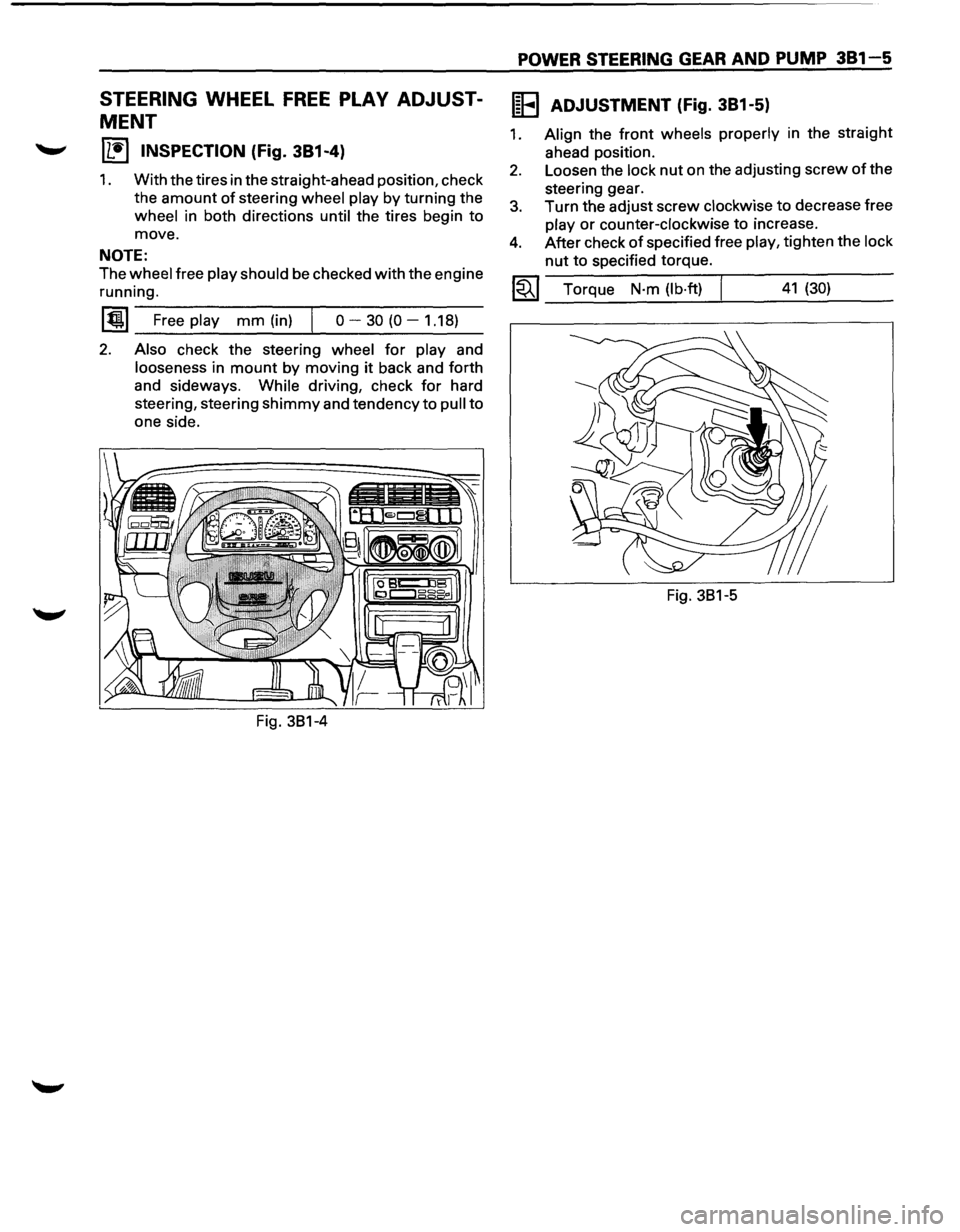
IL•I INSPECTION (Fig. 381-4)
1. With the tires in the straight-ahead position, check
the
amount of steering wheel play by turning the
wheel in both directions until the tires begin to
move.
NOTE:
The wheel free play should be checked with the engine
running.
~~~~F-r-ee--pl-ay---m-m--(in_)_,j--o----3-0-(0----1-.1-8~)-
2. Also check the steering wheel for play and
looseness in mount by moving it back and forth
and sideways.
While driving, check for hard
steering, steering
shimmy and tendency to pull to
one side.
POWER STEERING GEAR AND PUMP 381-5
IEEI ADJUSTMENT (Fig. 381-5)
1. Align the front wheels properly in the straight
ahead position.
2. Loosen the lock nut on the adjusting screw of the
steering gear.
3. Turn the adjust screw clockwise to decrease free
play or counter-clockwise to incre~se.
4. After check of specified free play, t1ghten the lock
nut to specified torque.
~~~ Torque N·m (lb·ft) I 41 (30)
Fig. 381-5
Page 144 of 1928
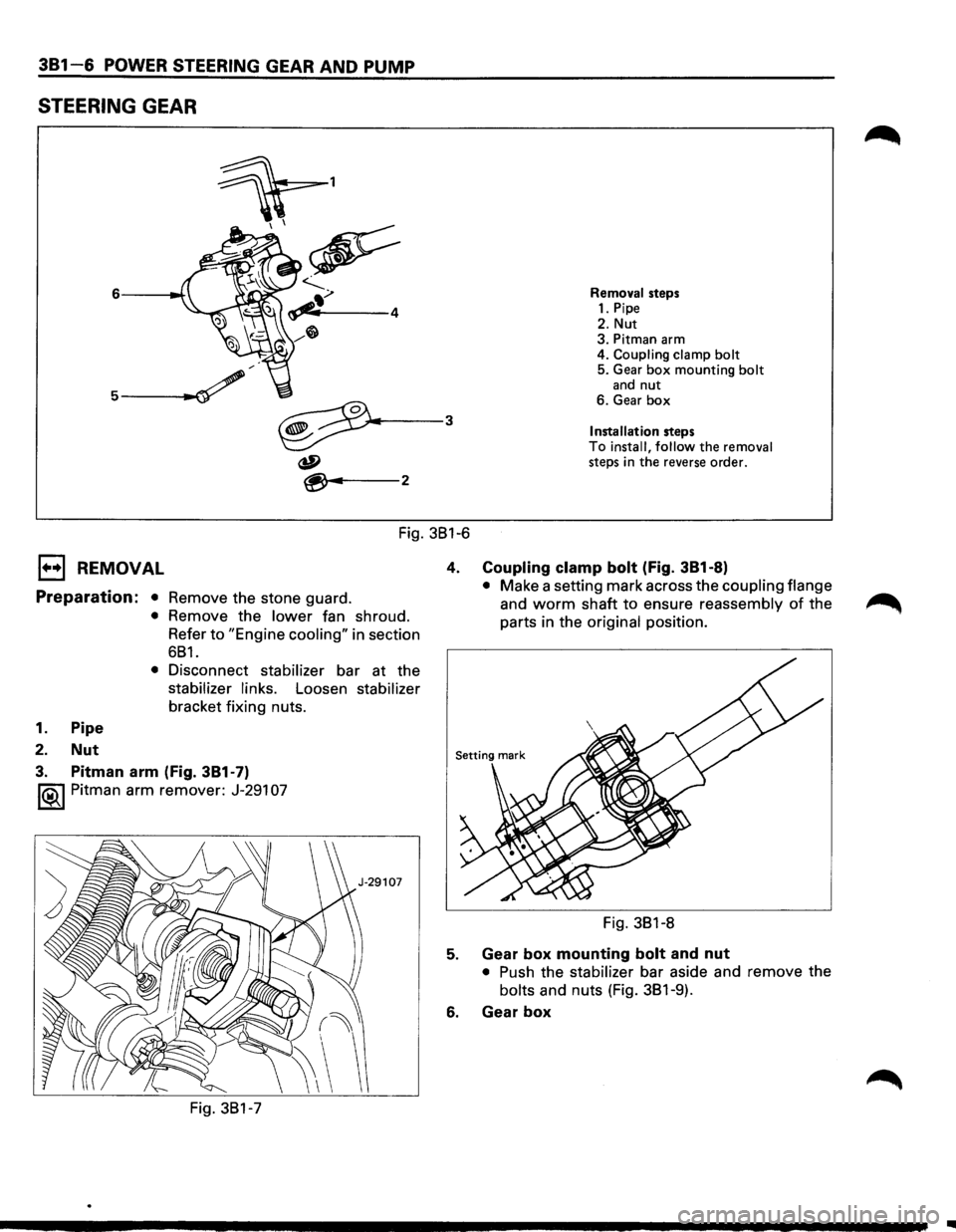
381-6 POWER STEERING GEAR AND PUMP
STEERING GEAR
Removal steps 1. Pipe
2. Nut 3. Pitman arm
4. Coupling clamp bolt 5. Gear box mounting bolt and nut 6. Gear box
Installation steps To install, follow the removal steps in the reverse order.
Fig. 381-6
EJ REMOVAL
Preparation: • Remove the stone guard.
1. Pipe
2. Nut
• Remove the lower fan shroud.
Refer to
"Engine cooling" in section
681.
• Disconnect stabilizer bar at the
stabilizer links. Loosen stabilizer
bracket fixing nuts.
3. Pitman arm (Fig. 381-7)
1®1 Pitman arm remover: J-291 07
Fig. 381-7 4.
Coupling clamp bolt (Fig.
381-8)
• Make a setting mark across the coupling flange
and worm shaft to ensure reassembly of the
parts in the
original position.
Fig. 381-8
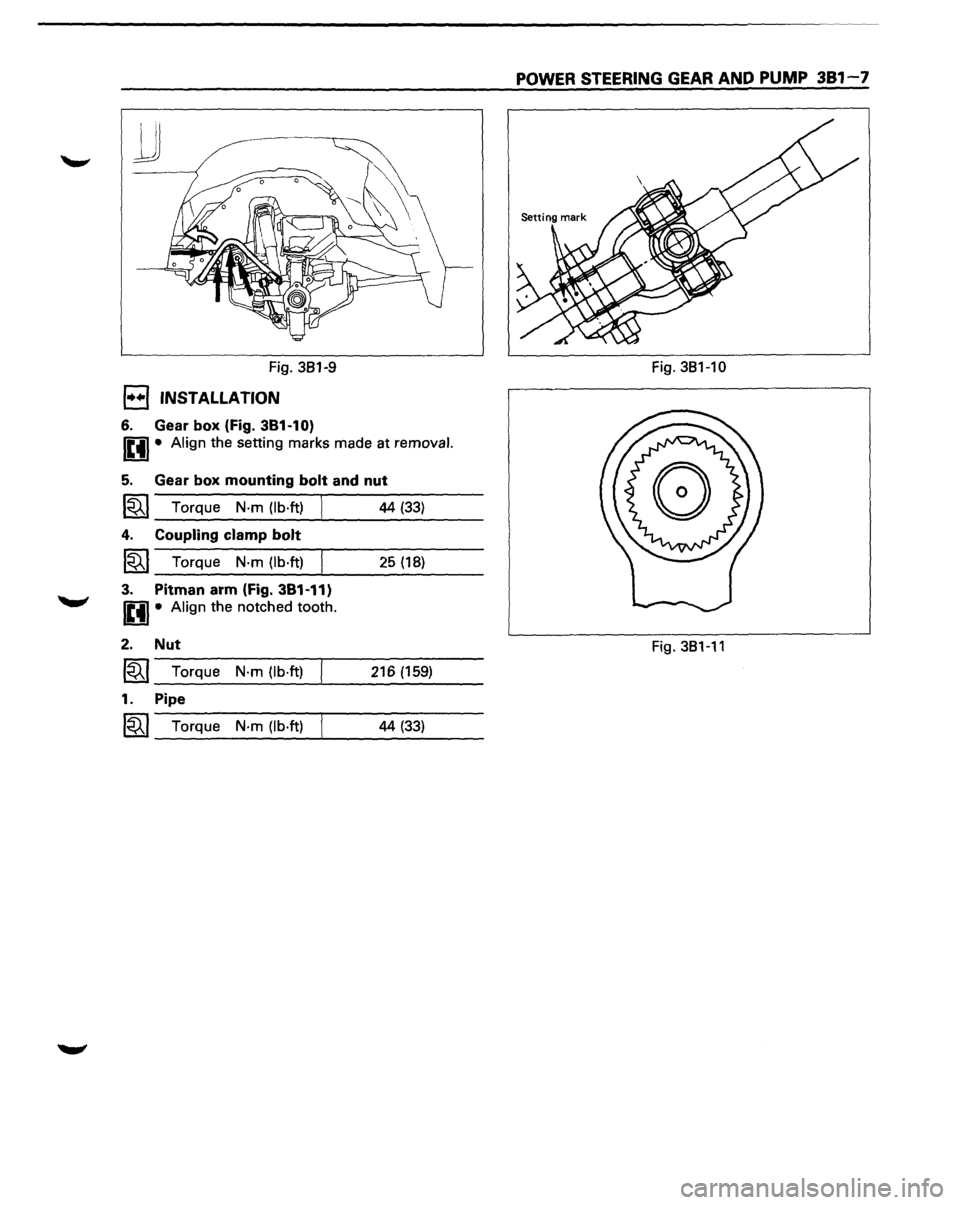
5. Gear box mounting bolt and nut
• Push the stabilizer bar aside and remove the
bolts and nuts (Fig. 381-9).
6. Gear box
..
Page 145 of 1928
lJ
Fig. 381-9
l••f INSTALLATION
6. Gear box (Fig. 381-1 0)
l£tj• Align the setting marks made at removal.
5. Gear box mounting bolt and nut
1~1 Torque N·m (lb·ft) 44 (33)
4. Coupling clamp bolt
~~~ Torque N·m (lb·ft) 25 (18)
3. Pitman arm (Fig. 381·11)
l£tj• Align the notched tooth.
2. Nut
~~~---T-o-rq_u_e __ N_·_m_(_lb-.ft-)~~---2-1_6_(1_5_9_) __ ___
1. Pipe
~~~--T-o-rq_u_e __ N--m----(-lb-.ft-)~-------4-4-(-33_) ____ _
POWER STEERING GEAR AND PUMP 381-7
Fig. 381-10
Fig. 381-11